VU657925792 Modular Radio Transceiver
City Theatrical, LLC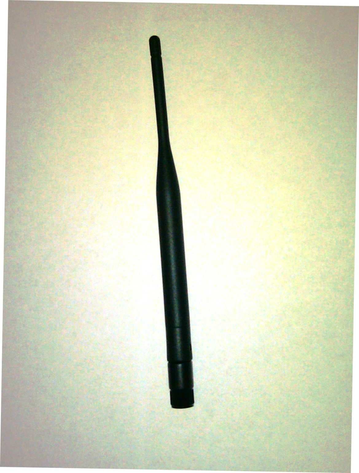
Click to zoom
Application Details
- Equipment Class
- DSS - Part 15 Spread Spectrum Transmitter
- Date of Grant
- Aug 21, 2011
- Application Purpose
- Original Equipment
- Date of Application
- Aug 21, 2011
- Equipment Note
- 5792 Modular Radio Transceiver
- Frequency Range
- 2406.00000000 - 2477.00000000
- Company
- City Theatrical, LLC
- Country
- United States
Documents & Files
Document Text
Text extracted from the exhibit documents filed with the FCC. Open a document above to read the original.
Users Manual
8 Important Information for OEM Integrators The 5792 SHoW DMX Neo Radio Module has been designed for use by OEM users in their own host equipment. The following information is provided to help guide the OEM integrator to implement the 5792 SHoW DMX Neo Radio Module in host designs in a way that meets FCC requirements. The following instructions include marking and labeling information, acceptable antenna requirements, information that must be included in the OEM Integrator’s product user’s manual, and other instructions. Regulatory Module Integration Instructions This module has been granted modular approval for mobile applications. OEM integrators for host products may use the module in their final products without additional FCC / IC (Industry Canada) certification if they meet the following conditions. Otherwise, additional FCC / IC approvals must be obtained. • The host product with the module installed must be evaluated for simultaneous transmission requirements. • The users manual for the host product must clearly indicate the operating requirements and conditions that must be observed to ensure compliance with current FCC / IC RF exposure guidelines. • To comply with FCC / IC regulations limiting both maximum RF output power and human exposure to RF radiation, the maximum antenna gain including cable loss in a mobile-only exposure condition must not exceed the limits as described in the following section on approved antennas: 5792 Approved Antennas To reduce potential radio interference to other users, the antenna type and its gain should be so chosen that the equivalent isotropically radiated power (E.I.R.P.) is not more than that permitted for successful communication. This device has been designed to operate with the antennas listed below. The model: 5792 can be configured with any one of the approved antennas listed below for fixed, point-to point one server and one client configuration. When the model: 5792 is configured for point-to-multipoint one server and multiple clients’ configuration (client’s talk to server only one at a time), client’s can use any of the approved antennas listed below and the server can use any of the approved antennas listed below with the exception of the 14dBi antenna. Manufacturer Model Type Connector Gain Nearson S151AH-2450S Omni whip SMA plug reverse polarity 5dBi Nearson S141AH-2450 Omni whip SMA plug reverse polarity 2dBi Nearson S131AH-2450 Omni whip SMA plug reverse polarity 2dBi Nearson DG102N-2.4/5.25 Omni whip SMA plug reverse polarity via provided Antenna Cable 5dBi Centurion WCP2400-MMCX4 Omni whip MMCX jack on 4” coax pigtail 2.5dBi Maxrad MP24008XFPT Panel SMA plug reverse polarity via 8dBi 9 provided Antenna Cable Maxrad MYP24010PT Yagi SMA plug reverse polarity via provided Antenna Cable 10dBi Maxrad MYP24014PT Yagi SMA plug reverse polarity via provided Antenna Cable 14dBi • A label must be affixed to the outside of the host product with the following statements: This device contains FCCID: VU65792 This equipment contains equipment certified under ICID: 7480A5792 The final host / module combination may also need to be evaluated against the FCC Part 15B criteria for unintentional radiators in order to be properly authorized for operation as a Part 15 digital device. If the final host / module combination is intended for use as a portable device (see classifications below) the host manufacturer is responsible for separate approvals for the SAR requirements from FCC Part 2.1093 and RSS-102. Device Classifications Since host devices vary widely with design features and configurations module integrators shall follow the guidelines below regarding device classification and simultaneous transmission, and seek guidance from their preferred regulatory test lab to determine how regulatory guidelines will impact the device compliance. Proactive management of the regulatory process will minimize unexpected schedule delays and costs due to unplanned testing activities. The module integrator must determine the minimum distance required between their host device and the user’s body. The FCC provides device classification definitions to assist in making the correct determination. Note that these classifications are guidelines only; strict adherence to a device classification may not satisfy the regulatory requirement as near-body device design details may vary widely. Your preferred test lab will be able to assist in determining the appropriate device category for your host product and if a KDB or PBA must be submitted to the FCC. Note, the module you are using has been granted modular approval for mobile applications. Portable applications may require further RF exposure (SAR) evaluations. It is also likely that the host / module combination will need to undergo testing for FCC Part 15 regardless of the device classification. Your preferred test lab will be able to assist in determining the exact tests which are required on the host / module combination. 10 FCC Definitions Portable: (§2.1093) — A portable device is defined as a transmitting device designed to be used so that the radiating structure(s) of the device is / are within 20 centimeters of the body of the user. Mobile: (§2.1091) (b) — A mobile device is defined as a transmitting device designed to be used in other than fixed locations and to generally be used in such a way that a separation distance of at least 20 centimeters is normally maintained between the transmitter’s radiating structure(s) and the body of the user or nearby persons. Per §2.1091d(d)(4) In some cases (for example, modular or desktop transmitters), the potential conditions of use of a device may not allow easy classification of that device as either Mobile or Portable. In these cases, applicants are responsible for determining minimum distances for compliance for the intended use and installation of the device based on evaluation of either specific absorption rate (SAR), field strength, or power density, whichever …
Text truncated - open the document above for the full version.
Users Manual
5792 SHoW DMX Neo™ Radio Module User’s Manual Rev 1.4 © 2011 City Theatrical Inc. SHoW DMX Neo™ devices are covered by U.S. Patent # 7,432,803 and other patents pending. 2 Table of Contents Specifications.................................................................................................................... 3 Regulatory Specifications ............................................................................................... 4 FCC Part 15 ................................................................................................................ 4 Radio Frequency Notifications.................................................................................... 4 Introduction ....................................................................................................................... 6 Features ............................................................................................................................. 6 Important Information for OEM Integrators ................................................................... 8 Regulatory Module Integration Instructions.................................................................... 8 Device Classifications..................................................................................................... 9 FCC Definitions............................................................................................................. 10 Simultaneous Transmission Evaluation ....................................................................... 10 OEM Instruction Manual Content ................................................................................. 11 Radio Configuration and Control.................................................................................. 12 Classic Mode Operation ............................................................................................... 12 Neo Mode Operation .................................................................................................... 12 Neo-Adaptive Mode Operation ..................................................................................... 12 Supported RDM PIDs ................................................................................................... 12 Antennas and Antenna Connectors ............................................................................. 13 Additional Support.......................................................................................................... 14 3 Specifications Table 1: Radio Module Specifications Physical Characteristics Size 1.65 x 2.7 x 0.26 ” [42.0 x 68.75 x 6.5mm] Mounting holes Compatible with Aerocomm AC5124 Connector 40 pin header – Amp P/N 177986-1 Antenna connector Horizontal MMCX coaxial receptacle Operating Temperature -20° to +70° C [-4 to 158° F] Storage Temperature -40° to +85° C [-40 to 185° F] DC Characteristics Input Voltage 5 Volts DC ±2%, ±5mV ripple Current draw 400mA maximum Sleep mode current 25mA maximum Transmitter Characteristics TX power Selectable 5mW to 75mW in four steps Frequency range 2406 to 2477 MHz Channels 2 sets 36 with 2 MHz channel spacing (72 total) Modulation FSK frequency hopping Over-the-air data rate 1 Mbps Channel coding 8B/10B line coding See note 1 Hopping patterns 2 sets of 36 full band, 2 sets of 16 low, mid, & high partial band selectable patterns with low cross-correlation, and selectable adaptive hopping algorithms. Receiver Characteristics RX sensitivity -90 dBm @ 1% PER Hop timing Synchronized with master transmitter Error checking CRC16 Serial Interface Logic levels 3.3 Volt / 5V Tolerant Bit rate Classic: 1.25 Mbps Neo: 250Kbps Data Format Classic: 8 N 1; Neo: 8 N 2 Flow Control None Note 1: Since there could be long stretches of continuous 1s or 0s in the transmitted data the radio transceiver IC will use 8B/10B line coding to ensure a more even distribution of 1s and 0s in the transmitted signal. This will provide better radio performance at the expense of a lower effective over-the-air bit rate. 8B/10B line coding is a method that encodes a symbol of 8 bits in to a 10 bit symbol and ensures that on average there is an even number over 1’s and 0’s and a minimum number of transitions. The effective bit rate becomes 8/10s of the radio bit rate so it will be 800kbps rather than 1Mbps. 4 Regulatory Specifications FCC Part 15 This equipment has been tested and found to comply with the limits for a Class B digital device, pursuant to part 15 of the FCC Rules. These limits are designed to provide reasonable protection against harmful interference in a residential installation. This equipment generates uses and can radiate radio frequency energy and, if not installed and used in accordance with the instructions, may cause harmful interference to radio communications. However, there is no guarantee that interference will not occur in a particular installation. If this equipment does cause harmful interference to radio or television reception, which can be determined by turning the equipment off and on, the user is encouraged to try to correct the interference by one or more of the following measures: • Reorient or relocate the receiving antenna. • Increase the separation between the equipment and receiver. • Connect the equipment into an outlet on a circuit different from that to which the receiver is connected. • Consult the dealer or an experienced radio/ TV technician for help. Radio Frequency Notifications FCC Notifications RF Radiation: The Product is an intentional radiator of Radio Frequency (RF) energy. In order to limit RF exposure to personnel in the immediate area, the Product should be located and installed such that a separation of at least 20 centimeters is maintained between the Product’s antenna and personnel in the vicinity of the device. The antenna used for this transmitter must not be co-located or operated in conjunction with any other antenna or transmitter. Modification warning: Caution - change…
Text truncated - open the document above for the full version.
Cover Letter(s)
FCC ID: VU65792 IC ID: 7480A-5792 Model: 5792 FCC Part 15 and RSS-210 Unlicensed Modular Transmitter Approval Justification Requirement Reference 1 The modular transmitter must have its own RF shielding. Yes. 2 The modular transmitter must have buffered modulation/data inputs Yes. The module has a microcontroller to buffer the data and control the radio modulation. See schematic. 3 The modular transmitter must have its own power supply regulation. Yes. The module has it’s own voltage regulator. See schematic. 4 The modular transmitter must comply with the antenna requirements of Section 15.203 and 15.204(c). Yes. 5 The modular transmitter must be tested in a stand-alone configuration, i.e., the module must not be inside another device during testing. Yes. The module is tested on a connector board but is not inside a case. 6 The modular transmitter must be labeled with its own FCC ID number, and, if the FCC ID is not visible when the module is installed inside another device, then the outside of the device into which the module is installed must also display a label referring to the enclosed module. Yes. Silkscreen on the bottom of the pcb. When the module is installed on a main pcb the FCC ID will be visible. 7 The modular transmitter must comply with any specific rule or operating requirements applicable to the transmitter and the manufacturer must provide adequate instructions along with the module to explain any such requirements. A copy of these instructions must be included in the application for equipment authorization. Yes. Refer to document “Application Manual”. 8 The modular transmitter must comply with any applicable RF exposure requirements. For example, FCC Rules in Sections 2.1091, 2.1093 and specific Sections of Part 15, including 15.319(i), 15.407(f), 15.253(f) and 15.255(g), require that Unlicensed PCS, UNII and millimeter wave devices perform routine environmental evaluation for RF Exposure to demonstrate compliance. In addition, spread spectrum transmitters operating under Section 15.247 are required to address RF Exposure compliance in accordance with Section 15.247(b)(4). Yes. Refer to document “Test Report”.
Cover Letter(s)
July 18, 2011 FCC ID: VU65792 Request for Confidentiality In accordance with 47 C.F.R. Section 0.459, we, City Theatrical, Inc., hereby request confidentiality for the following items: • Block Diagram • Schematic • Theory of Operation/Detailed Technical Description • Tune-up Procedure • Bill of Materials/Part List Enclosed within this application is technical information which we deem to be trade secrets and proprietary. If made public, the information might be used to our disadvantage. To assist in assuring that we receive the full value of our product and protect its competitive posture, we respectfully request this grant of confidentiality. Sincerely, Lauren E. Dunn (Larry) Head of Engineering – City Theatrical, Inc.
Cover Letter(s)
May 25, 2011 To Whom it May Concern, Re: City Theatrical, Inc. # 5792 Modular Radio Transceiver: FCC ID, Grantee Code, Grantee Code Registration number and FRN Number This is to confirm: City Theatrical, Inc. Grantee Code: VU6 City Theatrical, Inc. FCC ID for this product: VU65792 City Theatrical, Inc. Grantee Code Registration Number is GC446799 City Theatrical, Inc. FRN Number: 0017163338 City Theatrical, Inc. Contact Name: Mr. Lauren E. Dunn City Theatrical, Inc. Contact email: [email protected] Sincerely, Lauren E. Dunn (Larry) Head of Engineering – City Theatrical, Inc.
Cover Letter(s)
May 25, 2011 Intertek 1365 Adams Ct. Menlo Park, CA 94025 To Whom It May Concern: Intertek is authorized to act on our behalf, until otherwise notified, for applications to Intertek. We certify that we are not subject to denial of federal benefits, that includes FCC benefits, pursuant to Section 5301 of the Anti-Drug Abuse Act of 1988, U.S.C. 862. Further, no party, as defined in 47 CFR 1.2002 (b) to the application is subject to denial of federal benefits, that includes FCC benefits. Thank you. Regards, Lauren E. Dunn (Larry) Head of Engineering
External Photos
Antennas for City Theatrical 5792 Radio Module, Photos 1 Nearson S151AH-2450S Omni whip SMA plug reverse polarity 5dBi 2 Nearson S141AH-2450 Omni whip SMA plug reverse polarity 2dBi 3 Nearson S131AH-2450 Omni whip SMA plug reverse polarity 2dBi 4 Nearson DG102N-2.4/5.25 Omni whip SMA plug reverse polarity via provided Antenna Cable 5dBi 5 Centurion WCP2400-MMCX4 Omni whip MMCX jack on 4” coax pigtail 2.5dBi 6 Maxrad MP24008XFPT Panel SMA plug reverse polarity via provided Antenna Cable 8dBi 7 Maxrad MYP24010PT Yagi SMA plug reverse polarity via provided Antenna Cable 10dBi 8 Maxrad MYP24014PT Yagi SMA plug reverse polarity via provided Antenna Cable 14dBi
ID Label/Location Info
July 7, 2011 To Whom it May Concern, Re: City Theatrical, Inc. # 5792 Modular Radio Transceiver: Below are illustrations showing FCC and IC ID Markings on a typical host product and on the 5792 Modular Radio Transceiver PCBA. Host Product Marking Label The Label shall be either permanently molded or engraved into the case of the Host product or be printed on a permanent label in which the ink and label material is of a quality and type that will last the life of the device. In addition to being visible to the consumer, the label shall not be located on a removable part such as a battery cover. 2 5792 Modular Radio PCBA Silkscreen markings Sincerely, Lauren E. Dunn (Larry) Head of Engineering – City Theatrical, Inc.
Internal Photos
City Theatrical 5792 Radio Module bottom side City Theatrical 5792 Radio Module, component side, no shield City Theatrical 5792 Radio Module, component side, with shield 5dBi Omni antenna and MMCX -> reverse SMA cable
Test Report
EMC Report for City Theatrical, Inc. on the model: 5792 File: 100404100MPK-001 Page 1 of 119 TEST REPORT Report Number: 100404100MPK-001 Project Number: G100404100 Report Date: July 05, 2011 Testing performed on the Radio Module Model: 5792 FCC ID: VU65792 IC ID: 7480A-5792 to FCC Part 15.247 and RSS-210 Issue 8 for City Theatrical, Inc. Test Performed by: Test Authorized by: Intertek 1365 Adams Court Menlo Park, CA 94025 USA City Theatrical, Inc. 475 Barell Avenue Carlstadt, NJ 07072 USA Prepared by: Date: July 05, 2011 Krishna K Vemuri Reviewed by: Date: July 05, 2011 Ollie Moyrong This report is for the exclusive use of Intertek's Client and is provided pursuant to the agreement between Intertek and its Client. Intertek's responsibility and liability are limited to the terms and conditions of the agreement. Intertek assumes no liability to any party, other than to the Client in accordance with the agreement, for any loss, expense or damage occasioned by the use of this report. Only the Client is authorized to copy or distribute this report and then only in its entirety. Any use of the Intertek name or one of its marks for the sale or advertisement of the tested material, product or service must first be approved in writing by Intertek. The observations and test results in this report are relevant only to the sample tested. This report by itself does not imply that the material, product, or service is or has ever been under an Intertek certification program. This report must not be used to claim product endorsement by A2LA, NIST nor any other agency of the U.S. Government. EMC Report for City Theatrical, Inc. on the model: 5792 File: 100404100MPK-001 Page 2 of 119 Report No. 100404100MPK-001 Equipment Under Test: Radio Module Trade Name: City Theatrical, Inc. Model No.: 5792 FCC ID: VU65792 IC ID: 7480A-5792 Applicant: City Theatrical, Inc. Contact: Mr. Larry Dunn Address: 475 Barell Avenue Carlstadt, NJ 07072 Country USA Tel. Number: 201-549-1160 Fax number: 201-549-1161 Email: [email protected] Applicable Regulation: FCC Part 15, Subpart C RSS-210 Issue 8 Test Site Location: ITS – Site 1 1365 Adams Drive Menlo Park, CA 94025 Date of Test: June 24 to July 02, 2011 We attest to the accuracy of this report: Krishna K Vemuri EMC Senior Staff Engineer Ollie Moyrong Engineering Manager EMC Report for City Theatrical, Inc. on the model: 5792 File: 100404100MPK-001 Page 3 of 119 TABLE OF CONTENTS 1.0 Introduction .................................................................................................................................... 4 1.1 Summary of Tests................................................................................................................ 4 2.0 General Description ....................................................................................................................... 5 2.1 Product Description............................................................................................................. 5 2.2 Related Submittal(s) Grants ................................................................................................ 5 2.3 Test Methodology ............................................................................................................... 6 2.4 Test Facility......................................................................................................................... 6 3.0 System Test Configuration ............................................................................................................ 7 3.1 Support Equipment ............................................................................................................. 7 3.2 Block Diagram of Test Setup .............................................................................................. 7 3.3 Justification ......................................................................................................................... 8 3.4 Software Exercise Program ................................................................................................. 9 3.5 Mode of Operation During Test .......................................................................................... 9 3.6 Modifications Required for Compliance ............................................................................. 9 4.0 Measurement Results................................................................................................................... 10 4.1 Conducted Output Power at Antenna Terminals ............................................................... 10 4.2 Hopping Channel 20-dB Bandwidth and Occupied Bandwidth........................................ 17 4.3 Carrier Frequency Separation............................................................................................ 24 4.4 Number of Hopping Channels........................................................................................... 27 4.5 Average Channel Occupancy Time................................................................................... 46 4.6 Out-of Band-Conducted Emissions ................................................................................... 58 4.7 Transmitter Radiated Emissions........................................................................................ 64 4.8 Radiated Emissions from Digital Parts and Receiver ........................................................ 92 4.9 AC Line Conducted Emission......................................................................................... 105 5.0 RF Exposure Evaluation ........................................................................................................... 109 6.0 List of Test Equipment .............................................................................................................. 110 7.0 Document History ...................................................................................................................... 111 8.0 Appendi…
Text truncated - open the document above for the full version.
Test Setup Photos
Test Setup Photos FCC ID: VU65792 IC ID: 7480A-5792
Contact Information
Applicant
Paul Kleissler(Head of Engineeering)
Test Firm
Intertek Testing Services NA Inc.John Quigley
Technical Specifications
| # | Rule Parts | Frequency Range | Power Output |
|---|---|---|---|
| 1 | 15C | 2.41 GHz - 2.48 GHz | 26.00 mW |
Other Applications from City Theatrical, LLC
VU65792M
Dec 18, 20145792 Modular Radio Transceiver
Equipment Class
DTS - Digital Transmission System
VU65691
Mar 06, 2008SHOW DMX TRANSCEIVER
Equipment Class
DSS - Part 15 Spread Spectrum Transmitter
VU65692
Mar 06, 2008SHOW DMX TRANSCEIVER
Equipment Class
DSS - Part 15 Spread Spectrum Transmitter