VVOESP0913CFL
ZHEJIANG NVC LAMPS CO.,LTD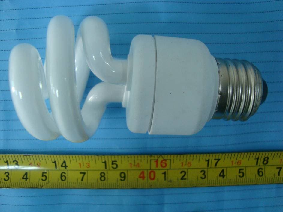
Click to zoom
Application Details
- Equipment Class
- 8CC - Part 18 Consumer Device
- Date of Grant
- Feb 06, 2011
- Application Purpose
- Original Equipment
- Date of Application
- Feb 06, 2011
- Equipment Note
- CFL
- Frequency Range
- 0.04000000 - 0.05000000
- Company
- ZHEJIANG NVC LAMPS CO.,LTD
- Country
- China
Documents & Files
Document Text
Text extracted from the exhibit documents filed with the FCC. Open a document above to read the original.
Users Manual
User Manual Dear Customer, Thank you for buying NVC Self-Ballast Lamp, Please read carefully the product instruction before using! The Model Name: ESP-9W and ESP-13W use only on 120 volt, 60Hz circuit. The wattage marked on the lamp. And the operating Frequency is more than 40 kHz and less than 50 kHz Features Energy Saves up to 75% compared to common incandescent Lamps Long lamp life, average 9 years High Lumens efficiency; Rapid on/off with silent operation; Reduces Carbon Dioxide Electromagnetic Volume Consumes natural resources Generate less heat in the building Note & Attention Always turn-off power before re-lamping; Avoid installing lamp by gripping the glass tube; Do not use with dimmers or electronic timers Reliable operating temperature -18°C~60°C Not suitable for damp surroundings or sealed occasions Risk of electric shock-use in dry locations For best result use in proper voltage range as mentioned on lamp base Applications: Home, Office, Hotel, Shop, Restaurant...and so on lighting FCC Information 1.This device complies with Part 18 of the FCC Rules. 2.Information on the following matters shall be provided to the user in the Instruction manual: (a) The interference potential of the device or system; (b) Maintenance of the system; (c) Simple measures that can be taken by the user to correct interference; (d) Manufacturers of RF lighting devices must provide an advisory statement, either on the product packaging or with other user documentation, similar to the following: This product may cause interference to radio equipment and should not be installed near maritime safety communications equipment or other critical navigation or communication equipment operating is in between 40 kHz and 50 kHz. Variations of this language are permitted provided all the points of the statement are addressed and may be presented in any legible font or text style.
Block Diagram
Circuit Block Diagram 120V 60Hz Input EMI Filter Circuit Rectification Circuit Filter Circuit Oscillating Circuit Fuse L N L A M P
External Photos
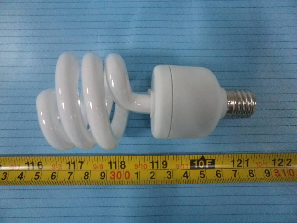
EXHIBIT B - EUT EXTERNAL PHOTOGRAPHS EUT – View (Model: ESP-9W) EUT – View (Model: ESP-13W)
ID Label/Location Info
EXHIBIT A - FCC ID LABEL AND LOCATION FCC ID Label FCC ID Label Location Information Specifications: Text is Black or white in color and is left justified. Labels are printed in indelible ink on permanent adhesive backing or silk-screened onto the EUT or shall be affixed at a conspicuous location on the EUT. Label here Model: ESP-9W Model: ESP-13W
Internal Photos
EXHIBIT C - EUT INTERNAL PHOTOGRAPHS EUT – Cover off View (Model: ESP-9W) EUT – Mainboard Top View (Model: ESP-9W) EUT – Main Board Bottom View (Model: ESP-9W) EUT – Cover off View (Model: ESP-13W) EUT – Mainboard Top View (Model: ESP-13W) EUT – Main Board Bottom View (Model: ESP-13W)
Operational Description
Circuit Description Fuse:When input is shorted, it performs input shorted protect function. L1、C1:Work together with to perform EMI function. D1、D2、D3、D4:Performs rectification function. Q1、Q2:Performs Oscillating function, let low frequency switch high frequency. L2、C5、C6、C7:When switching power, the L2 and C7 take place series resonance startup the lamp, then L2 restricting current.
Parts List/Tune Up Info
Parts list Model Name: ESP-9W, ESP-13W NO COMPONENT TYPE/RATINGS Φ10 S 2T9W 7~8Ω 1 bulb Φ10 S 3T13W 7~8Ω 2 PCB NVC-33 PFR-1 94 V-0 9W /13W 3 Plastics Φ39.6 PBT 0.8mm V2 9W/13W 4 Transistor Q1/Q2 4124DL TO-92 β:20-25 Ts:≤3.5 9W/13W 5 Diode D1~D5 M7 1000V 6 Diode DB3 DB3 28V-36V 2A 7 Capacitor C7 332/1000V CH11 9W/13W 8 Capacitor C6 332/1000V CH11 9W/13W 9 Capacitor C4 223/50V SMD 0805 10 Capacitor C3 102/1000V CH11 9W/13W 11 CapacitorC1、 C5 472/250V CL21 9W/13W 10μF/200V 105°C 5000h 9W 12 Capacitor C2 10μF/200V 105°C 5000h 13W 13 Resistor R1/R2 SMD 1206 330KΩ 1/4W 14 Resistor R3/R4 SMD 1206 27Ω 1/4W 9W/13W 16 P1~P4 0.65*0.65*10 17 UL FUSE L RXF-0.47Ω 1W EE13 2.0±0.1mH φ0.23 9W EE13 1.5±0.1mH φ0.25 13W Adhesive Tape 130°C 18 Choke trans(L2) Magnet wire EUW 155°C Main trans. φ6*8 0.4mH φ0.21 Magnet wire QA-2 155°C 19 Main trans.(L1) Adhesive Tape JY-133 130°C 20 Lead wire(N) 105°C 300 V ac 24AWG 80±1.0 mm φ9*5*3 3:8:3 2.5K 9W 21 O trans (T1) φ9*5*3 3:8:3 5K 13W 22 Bobbin Plastic BK V-0/150°C 23 Magnet wire 155°C
Schematics
ESP-9W,ESP-13W
Test Report
Note: This test report is prepared for the customer shown above and for the device described herein. It may not be duplicated or used in part without prior written consent from Bay Area Compliance Laboratories Corp. This report must not be used by the customer to claim product certification, approval, or endorsement by NVLAP*, NIST, or any agency of the Federal Government. * This report contains data that are not covered by the NVLAP accreditation and are marked with an asterisk “★” (Rev.2) FCC PART 18 MEASUREMENT AND TEST REPORT For ZHEJIANG NVC LAMPS CO., LTD. NO 201-16, TONGDA ROAD, SOUTH ZONE, HUSHAN DISTRICT, JIANGSHAN, ZHEJIANG, CHINA FCC ID: VVOESP0913 Report Type: Original Report Product Type: CFL Test Engineer: Abel Yang Report Number: RSZ10102552 Report Date: 2011-01-20 Reviewed By: Lisa Zhu EMC Engineer Prepared By: Bay Area Compliance Laboratories Corp. (Shenzhen) 6/F, the 3rd Phase of WanLi Industrial Building, ShiHua Road, FuTian Free Trade Zone Shenzhen, Guangdong,China Tel: +86-755-33320018 Fax: +86-755-33320008 ZHEJIANG NVC LAMPS CO., LTD. FCC ID: VVOESP0913 Report No.: RSZ10102552 Page 2 of 16 FCC Part 18 Report TABLE OF CONTENTS GENERAL INFORMATION.......................................................................................................................................3 PRODUCT DESCRIPTION FOR EQUIPMENT UNDER TEST (EUT) .....................................................................................3 OBJECTIVE...................................................................................................................................................................3 RELATED SUBMITTAL(S)/GRANT(S).............................................................................................................................3 TEST METHODOLOGY..................................................................................................................................................3 TEST FACILITY.............................................................................................................................................................3 SYSTEM TEST CONFIGURATION ..........................................................................................................................5 JUSTIFICATION.............................................................................................................................................................5 EUT EXERCISE SOFTWARE..........................................................................................................................................5 SPECIAL ACCESSORIES.................................................................................................................................................5 EQUIPMENT MODIFICATIONS.......................................................................................................................................5 EXTERNAL I/O CABLE..................................................................................................................................................5 CONFIGURATION OF TEST SETUP.................................................................................................................................6 BLOCK DIAGRAM OF TEST SETUP................................................................................................................................6 CONDUCTED EMISSIONS ........................................................................................................................................7 MEASUREMENT UNCERTAINTY....................................................................................................................................7 EUT SETUP..................................................................................................................................................................7 EMI TEST RECEIVER SETUP.........................................................................................................................................8 TEST EQUIPMENT LIST AND DETAILS...........................................................................................................................8 TEST PROCEDURE........................................................................................................................................................8 TEST RESULTS SUMMARY............................................................................................................................................8 TEST DATA..................................................................................................................................................................8 RADIATED EMISSIONS...........................................................................................................................................13 MEASUREMENT UNCERTAINTY..................................................................................................................................13 EUT SETUP................................................................................................................................................................13 EMI TEST RECEIVER SETUP AND SPECTRUM ANALYZER SETUP................................................................................14 TEST EQUIPMENT LIST AND DETAILS.........................................................................................................................14 TEST PROCEDURE......................................................................................................................................................14 CORRECTED AMPLITUDE CALCULATION....................................................................................................................14 TEST DATA................................................................................................................................................................14 PRODUCT S…
Text truncated - open the document above for the full version.
Test Setup Photos
EXHIBIT D - TEST SETUP PHOTOGRAPHS Conduction Emissions - Front View (Model: ESP-9W) Conduction Emissions - Side View (Model: ESP-9W) Conduction Emissions - Front View (Model: ESP-13W) Conduction Emissions - Side View (Model: ESP-13W) Radiated Emissions - Front View (Model: ESP-9W) Radiated Emissions - Rear View (Model: ESP-9W) Radiated Emissions - Front View (Model: ESP-13W) Radiated Emissions - Rear View (Model: ESP-13W)
Contact Information
Applicant
Tao 324100 Yang(Engineer)
Test Firm
Bay Area Compliance Laboratory Corp. (Shenzhen)John Chan
Technical Specifications
| # | Rule Parts | Frequency Range | Power Output |
|---|---|---|---|
| 1 | 18 | 0.04 MHz - 0.05 MHz | - |
Other Applications from ZHEJIANG NVC LAMPS CO.,LTD
VVOESP13
Jan 11, 2012CFL
Equipment Class
8CC - Part 18 Consumer Device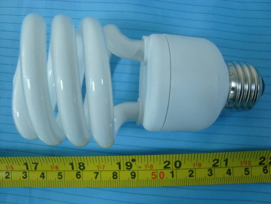
VVOESP1820
Jan 20, 2011CFL
Equipment Class
8CC - Part 18 Consumer Device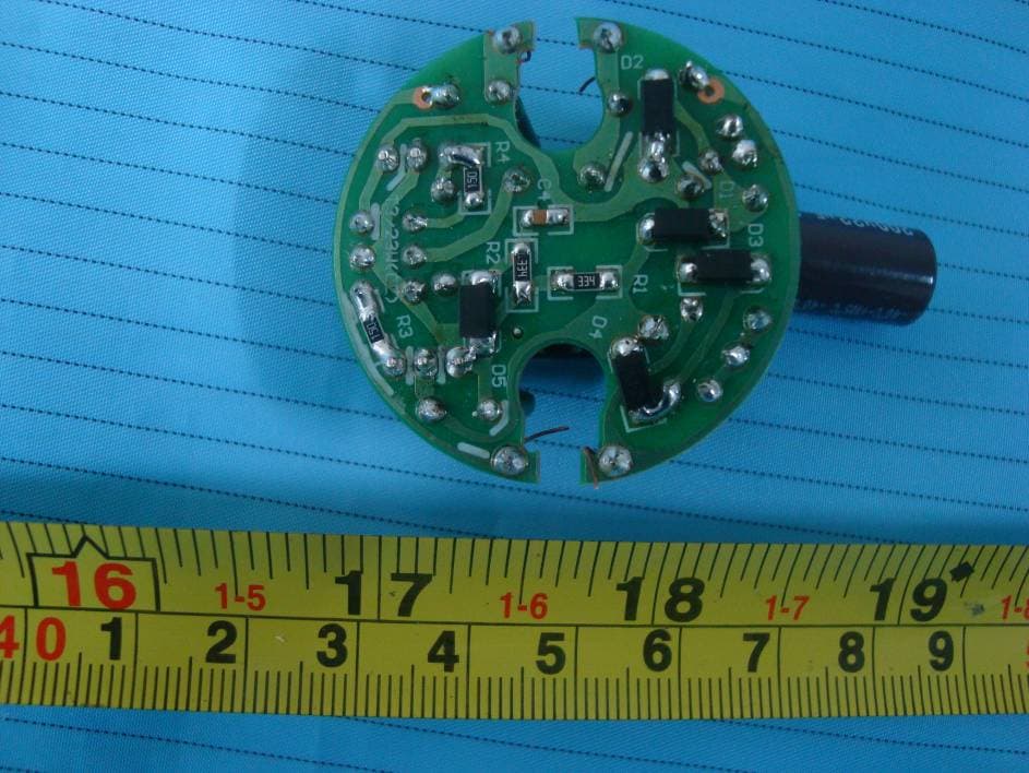
VVOESP23
Jan 20, 2011CFL
Equipment Class
8CC - Part 18 Consumer Device
VVOESS-13W-23W
Sep 12, 2010Self-Ballasted lamp
Equipment Class
8CC - Part 18 Consumer Device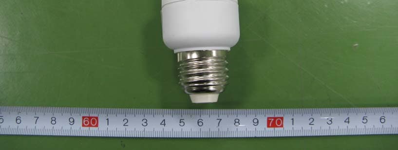
VVOT30915
Dec 27, 2007CFL
Equipment Class
8CC - Part 18 Consumer Device