VYM20-0108-4-E-S2MINI RESPONDER
Wartsila Guidance Marine Ltd.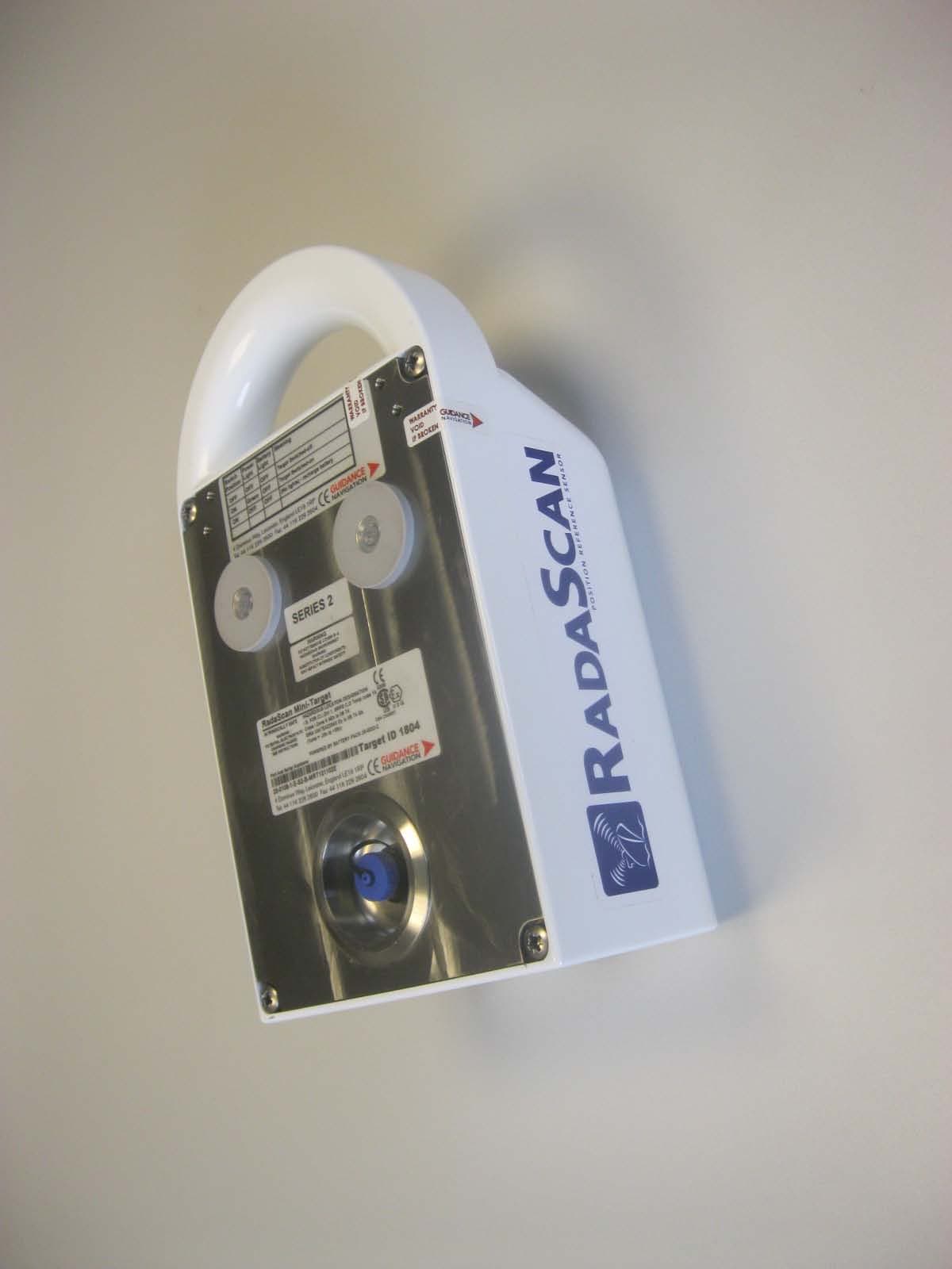
Click to zoom
Application Details
- Equipment Class
- MRD - Marine Radar
- Date of Grant
- Apr 22, 2013
- Application Purpose
- Original Equipment
- Date of Application
- Apr 21, 2013
- Equipment Note
- MINI RESPONDER
- Frequency Range
- 9200.00000000 - 9300.00000000
- Country
- United Kingdom
Documents & Files
Document Text
Text extracted from the exhibit documents filed with the FCC. Open a document above to read the original.
Users Manual
1 4 Author: Jan GrothusenIssue Date: 09/05/2011 Doc No: 94-0199-4-A Operation The target must always be used with its longest side vertical. Switch the unit off when not in use to preserve the battery. ! The target is water resistant to IP66. However, do not submerge the unit in water. To Switch the Target ON: 1. Press the ON/OFF button on the top of the unit. 2. The green light should be permanently lit when unit is in operation. Under normal conditions with a fully charged battery, the rechargeable target will operate continuously for up to 640 hours before it needs recharging. ! When the unit is switched on and no green light is shown, then the battery requires charging. ON/OFF Button Power Light Charging The rechargeable target should be fully charged before use. A full charge takes approximately 24 hours. ! DO NOT charge targets in an explosive atmosphere or other hazardous environment. The target should be switched off while charging. (Both lights off). To Charge the Target: ! Note: Only use the supplied charger. 1. Switch the target off and unscrew the charging socket cap on the rear of the unit. 2. Connect the supplied mains charger (Part No 39-0033-2). (Input: 100–240VAC, 50–60Hz, 1.5A Output: 24VDC, 2.5A, 60W). 3. When charging is complete, disconnect the power from the unit and replace the charging socket cap. Rechargeable Target—Rear Charging Socket RadaScan Mini-Target Guide ATEX Certification LabelMini-Target Mini-Target—Front Instructions for Safe Selection, Installation, Use, Maintenance, Repair and Transport User instructions (in compliance with ATEX 94/9/EC Directive, Annex II, 1.0.6) Mini Target Part Numbers: 20-0108-1 and 20-0110-1 ATEX Certificate Number: SIRA 10ATEX2254X Use in Hazardous Environments XTargets may be used in zones 0, 1, or 2 with flammable gases. XTargets may be used in the presence of flammable gases and vapours with apparatus groups IIB or IIA and with temperature classes T1 or T2 or T3 or T4. XThe equipment is certified for use in ambient temperatures in the range of −25°C to +55°C and should not be used outside this range. Installation and Maintenance XTargets must be installed by suitably trained personnel in accordance with the applicable code of practice (typically IEC EN 60079-14). XTargets must be inspected regularly by suitably trained personnel in accordance with the applicable code of practice to ensure they are maintained in a satisfactory condition. XTargets are not intended to be repaired by the user. They must only be repaired or serviced by Guidance Navigation Ltd, or by an approved service representative of Guidance Navigation Ltd, in accordance with the applicable code of practice. XTargets do not require assembly or dismantling. They do not contain any customer-replaceable parts, and no user adjustment is required. Electrostatic Hazard XTargets must not be installed where external conditions could cause an electrostatic build-up on their outer casing. XThe target’s outer casing presents a static hazard and must only be cleaned using a damp cloth. Corrosive Substances XTargets should be protected from solvents, or acidic gases or liquids that may affect the integrity of its outer case. Transport XTargets must be transported in a suitable transit case. Mini-Targets can be used with RadaScan and Mini-RadaScan systems. One or more targets should be mounted on the target platform or vessel. There are two models of Mini-Target: XRechargeable (Part No 20-0108-1-S2-*) XNon-rechargeable (Part No 20-0110-1-S2-*) (The non-rechargeable variant requires battery pack replacement as routine maintenance. This should be undertaken by Guidance Navigation Limited, or a suitably qualified service technician). ! Do not open the target. It should only be serviced by Guidance Navigation Limited, or a suitably qualified service technician. If you experience any problems with the unit, please contact: Guidance Navigation Ltd 4 Dominus Way Meridian Business Park Leicester Tel: +44 (0) 116 229 2600 LE19 1RP Fax: +44 (0) 116 229 2604 United Kingdom Email: [email protected] RadaScan Mini-Target INTRINSICALLY SAFE Part And Serial Numbers: *20-01XX-X-X MRT100XXXX* 20-01XX-X-X MRT100XXXX 4 DOMINUS WAY, LEICESTER, ENGLAND, LE19 1RP, UK TEL: 44 116 229 2600 FAX: 44 116 229 2604 II 2G 0359 WARNING POTENTIAL ELECTROSTATIC CHARGING HAZARD SEE INSTRUCTIONS HAZARDOUS LOCATION DESIGNATION I.S. FOR Cl.I, DIV.1, GRPS C,D, Temp. Code T4 Class I, Zone 0 AEx ia IIB T4 SIRA 10ATEX2254X Ex ia IIB T4 Gb (Tamb = -25C to +55C) POWERED BY BATTERY PACK 39-0034-2 (Series 2) US CSA 2368857 3 2 Loosen the nut to swivel the bracket in the required direction. ! Tighten the nut with a spanner to fix the bracket’s position. Mounting The mini-target can be used with or without a swivel bracket, as long as it is mounted with its longest side vertical, and its carrying-handle at the top. To Mount the Target: 1. Hook the foot of the target underneath the knob on the bottom of the mounting plate. (See right). 2. Rotate the target backwards until it is held in place by its magnets against the mounting plate. Knob Mounting Plate Magnet Swivel Bracket Mounting on Horizontal BarMounting on Vertical Bar Swivel Bracket Swivel Bracket The swivel bracket (Part No 21-0275-1) should be used to point the target towards the RadaScan vessels’ working area. It can be mounted on either a horizontal or vertical bar: Positioning The location, range and orientation of the targets in relation to the sensor have a significant effect on the tracking performance of the RadaScan / Mini-RadaScan systems, and hence on the quality of the position data sent to the DP system. RadaScan is a radar-based system. Metallic structures reflect the microwave beam transmitted by the sensor, and can cause multipath interference, where ghost images are reported by the system. However, this unwanted phenomenon can be prevented by carefully positioning the targets according to the following guidelines: Targets Should be …
Text truncated - open the document above for the full version.
Block Diagram
CMR‐1141 Company Confidential RadaScan Mini Responder Technical Description Page 8 of 9 Issue 1 7 th March 2013 Company Confidential 3. SYSTEM BLOCK DIAGRAM Figure 3.1 below shows a System Block Diagram for the Mini RadaScan Responder. 3.1 Figure 3.1, RadaScan Mini Responder System Block Diagram There are 2 electronic PCBs: the RF Board and the Modulator Board. The battery supply is connected to the Modulator board which has the voltage regulation circuitry. The charger input is nominally +24V and is connected to the battery via charging electronics on the Modulator board. Two clocks drive an FPGA which is used to generate the modulation signals with a maximum frequency of 3MHz to the RF board. The FPGA monitors for correct operation and battery status, controlling 2 LEDs to indicate operational status to the user. The front of the Responder is a radome allowing the reception and transmission of the microwave signals to the RF board. Modulation Amplifier Amplifier 3MHz Max Receive Antenna (Vertical) Transmit Antenna (Horizontal) RF BOARD RF_PL1 +3.3V -3.3V Max 3MHz Mod DC Logic Signals J4 MODULATOR BOARD REGULATORS J3 BATTERY +1.2V TO +6V +1.2V +3.3V -3.3V FPGA 35MHz Clock 32.768kHz Clock CHARGE INPUT +24V J1 J2 RED LED GREEN LED ON/OFF SWITCH Max 3MHz RadaScan Mini Target CHARGING CIRCUIT
Cover Letter(s)
12th September 2012, Page 1 of 4 Ref: FCC Inquiry 418995/397862. RECEIVED & INSPECTED GUIDANCE SEP 7201? MICROWAVE FCC..GG MA?LROM RADASCAN MINI RESPONDER FCC WAIVER REQUEST 1. INTRODUCTION We have developed a new active Responder to operate with our range of RadaScan Marine position reference sensors operating in the band 9.2GHz to 9.3GHz.The RadaScan sensor links into ship Dynamic Positioning systems and allows the ship to manoeuvre accurately relative to a known Responder position. Typically, the active Responder is located on an Oil Rig and the RadaScan sensor measures range and bearing to the Responder.The Responder can also be used for ship to ship tracking to aid Replenish At Sea operations. DP systems in safety critical areas (like Oil Rig supply) require a high level of redundancy and therefore a number of independent technology position sensors, typically using GPS and lasers for two of the sensor types. Both of these systems are vulnerable to poor weather conditions and GPS is susceptible to shadowing from large structures, multipath reflections and GPS outages during solar storms; Radar technology is ideal as a reliable, all weather Position Sensor. We wish to apply for FCC approval for our active Responder; the RadaScan Mini Responder. Details of the Mini Responder can be found in our online inquiry references 418995and 397862. This Responder does not contain a transmitting source of its own and as such does not generate any Microwave signals. It is designed to receive the Microwave signal from the RadaScan sensor, amplify it, modulate it with a frequency in the range 1 IVlHz to 3MHz and re-transmit the signal back to the sensor with a cross polarized antenna. Essentially, the Responder appears as a flashing corner reflector of less than 13cm in length. The maximum EIRP from the Mini Responder is 1 3dBm from a limiting output power of 4dBm and a transmit antenna gain of 9dBi. At a range of greater than 1 m from the Responder, the field strength transmitted by the Responder is less than that arriving at it. More information on the Mini Responder can be found in CMR- 1141, RadaScan Mini Responder Technical Description. This is very similar to our competitor's product, Radius (FCC ID Q8IKSXRADIUS), which has FCC approval for80.375(d)in the band 5470- 5650MHz. Radius uses a very similar active Responder with similar modulation. 001 Guidance Microwave Limited C2, Knowl Piece Wilbury Way Hitchin, Herts, SG4 OTY, UK Company Registered in England No. 03075144 Telephone: +44 (0)1462 423449 Fax: +44 (0)1462 423552 Email: [email protected] Website: www.guidance.eu.com VAT No. GB 108 2469 21 Microwave Engineering , R:ering 12th September 2012, Page 2 of 4 Ref: FCC Inquiry 418995/397862. GUIDANCE MICROWAVE Microwave Engineering It is understood that the Responder operates a little like a standard active Radar Responder Enhancer (RTE) as described by ITU-R.M 1176. However, such a device would be of little or no use positioned on a large ship or oil rig since the rig or vessel itself has a significantly larger Radar Cross Section than either a large passive Responder or an active RTE. Hence the need to add modulating signals to allow the Responder to be detected against the background clutter. Similarly, the use of cross polarisation improves the Responder discrimination against background clutter. These features also reduce the visibility of our Responder to standard radars; the cross polarisation will give a minimum of 6dB attenuation, more typically 15dB and the modulation signal will tend to shift the signal outside of the Doppler signal processing (1MHz is equivalent to over 36,000mph). These Responders have been operating in Europe for over 5 years with no reported interference with Radar systems (or any other system for that matter). We understand our Responder to be a radiodetermination device as covered by 80.375(d) but we wish to use the frequency band of 9200MiHz to 9300MHz to avoid interference from standard high power pulse radars operating from 9300MHz to 9500MHz. Therefore we request a waiver of 80.375(d). am Guidance Microwave Limited C2, Knowl Piece Wilbury Way Hitchin, Herts, SG4 OTY, UK Company Registered in England No. 03075144 Telephone: +44 (0)1462 423449 Fax: +44 (0)1462 423552 Email: [email protected] Website: www.guidance.eu.com VAT No. GB 108 2469 21 RF Engineering 12th September 2012, Page 3 of 4 Ref: FCC Inquiry 418995/397862. GUIDANCE MICROWAVE Microwave Engineering 2. PROPOSED TESTING The following is the proposed testing against the requirements of FCC part 80 for Radiodetermination devices, largely based on the approvals testing performed for the Radius system. 2.1 Class of Emissions 80.207 (d):Radiodetermination 2.4-9.6GHz, Class PON 2.2 Radiated Power 80.2 15 (n) (3): Maximum of 20W EIRP. Apply a signal of 9.25GHz with a power density of -8dBW/m2 (high enough to ensure the maximum power output from the Responder) and measure the mean power radiated by the Responder. This is expected to measure around 20mW EIRP, 30dB below the allowed maximum. 2.3 Emissions Limitations 80.211 (f): 50%to 100% offset >25dB, 100% to 250% offset >35dB and 250% offset >43+ 1 Olog(mean) dB. Apply signals of 9.20GHz, 9.25GHz and 9.3GHz with a power density of at least -8dBW/m2and measure spurious emissions from 0.4GHz to 40GHz. 2.4 Frequency Tolerance 80.209(c):To be specified in the licence. The Responder has no transmitting source and so takes the frequency tolerance of the sensor used with it. Apply a signal at 9.25GHz and measure that the retransmitted frequency is the same as that received plus the modulation frequency (1.75MHz to 3MHz). 2.5 Modulation Requirements 80.213(g):Any type of modulation consistent with the bandwidth requirements of 80.2 09(b). The modulation bandwidth applied by the Responder is a maximum of 6MIHz (±3MHz). Apply a signal of 9.25GHz with a power density of -8dB W/m2 and measure the retransmitted modulation bandwidth. 001 Guidance Microwave Lim…
Text truncated - open the document above for the full version.
ID Label/Location Info
Doc Number 93-0062-4 PAGE 21 OF 21 e. Mark out dimensions as shown below on Backplate using pencil and engineers square. Masking tape is not needed. Apply Stickers in correct place as shown on the diagram. f. Wipe away any pencil markings and ensure that backplate is clean. Apply Coloured Dot sticker to front of case if the target has been programmed as SSB g. Final clean and inspect the completed mini Transponder Assembly.
Operational Description
CMR‐1141 Company Confidential RadaScan Mini Responder Technical Description Page 1 of 9 Issue 1 7 th March 2013 Company Confidential DAVE PATRICK 7 TH MARCH 2013 CMR-1141 RADASCAN MINI RESPONDER TECHNICAL DESCRIPTION CMR‐1141 Company Confidential RadaScan Mini Responder Technical Description Page 2 of 9 Issue 1 7 th March 2013 Company Confidential Contents 1. INTRODUCTION ....................................................................................................................... 3 1.1 Figure 1.1, External View .................................................................................................. 3 1.2 Figure 1.2, Functional Block Diagram of the Mini Responder ....................................... 4 2. PERFORMANCE PROPERTIES ............................................................................................. 5 2.1 Power Consumption ........................................................................................................... 5 2.2 Operating Frequency ......................................................................................................... 5 2.3 Amplifier Gain .................................................................................................................... 5 2.4 Antenna Gain ...................................................................................................................... 5 2.5 Maximum Transmitted Power .......................................................................................... 5 2.6 Maximum Transmitted EIRP ............................................................................................ 5 2.7 Effective Radar Cross Section ........................................................................................... 5 2.8 Frequency Response ........................................................................................................... 6 2.9 Modulation .......................................................................................................................... 6 2.10 Azimuth Radiation Patterns .............................................................................................. 6 2.10.1 Figure 2.10.1, Azimuth Beam Patterns .................................................................... 6 2.11 Elevation Radiation Pattern .............................................................................................. 7 2.11.1 Figure 2.11.1, Elevation Beam Pattern..................................................................... 7 3. SYSTEM BLOCK DIAGRAM .................................................................................................. 8 3.1 Figure 3.1, RadaScan Mini Responder System Block Diagram ..................................... 8 4. TUNE UP PROCEDURE ........................................................................................................... 9 CMR‐1141 Company Confidential RadaScan Mini Responder Technical Description Page 3 of 9 Issue 1 7 th March 2013 Company Confidential 1. INTRODUCTION The RadaScan Mini Responder is an active radar responder designed for use with the RadaScan range of position sensors operating in the band 9.2GHz to 9.3GHz. The RadaScan sensor measures range and bearing to the active Responder for use with Dynamic Positioning (DP) systems on Marine Vessels. The Responder receives the microwave signal from the RadaScan sensor with a vertically polarized patch array, amplifies and modulates the signal before re-transmitting it with a horizontally polarized patch array. Figure 1.1 below shows an external view of the Responder. 1.1 Figure 1.1, External View CMR‐1141 Company Confidential RadaScan Mini Responder Technical Description Page 4 of 9 Issue 1 7 th March 2013 Company Confidential Figure 1.2 below illustrates the function of the Responder. 1.2 Figure 1.2, Functional Block Diagram of the Mini Responder There is a more detailed Block Diagram in Figure 3.1 later. The RadaScan sensor is a Frequency Modulated Continuous Wave (FMCW) Radar so the Responder operates in CW mode, returning an amplified version of the received signal back to the sensor; the Responder doesn’t contain an RF source of its own. Power for the Responder is obtained from batteries with both re-chargeable and primary cell options being available. There are two main versions of the Responder: 180° and 360°. The 360° version is simply made from the 180° version with additional RF board on the back. The Responder is compact at just 260mm high and light weighing less than 4kg for the 180° version. CMR‐1141 Company Confidential RadaScan Mini Responder Technical Description Page 5 of 9 Issue 1 7 th March 2013 Company Confidential 2. PERFORMANCE PROPERTIES 2.1 Power Consumption The total power consumption of the 180° Responder is typically 140mW, nominally from a 4V source and a drain of 35mA. The total power consumption of the 360° Responder is typically 240mW, nominally from a 4V source and a drain of 60mA. 2.2 Operating Frequency The Nominal operating frequency band (peak gain) is 9.2 to 9.3GHz. 2.3 Amplifier Gain The total gain through the amplifier and modulation chain is 30dB. This is made of 40dB amplifier gain and 10dB loss through the modulator. 2.4 Antenna Gain The Antenna gain measurements are summarised in report CMR-1163. The peak transmit antenna gain is 11.9dBi. The peak Receive antenna gain is 12.25dBi. 2.5 Maximum Transmitted Power The maximum transmitted power is 4dBm. The maximum power is output when the last amplifier in the chain saturates. All of the RF amplifiers are made using Eudyna FHX35LG low noise FETs. These have a specified saturated output power of around 16dBm with a drain current of 15mA. The Mini Responder uses drain currents of 3mA to conserve battery life and this gives a measured saturated output power of 4dBm. 2.6 Maximum Transmitted EIRP The maximum transmitted EIRP is 15.9dBm. This is from a maximum output power of 4dBm and a transmit antenna gain of 11.9dBi. 2.7 Effective…
Text truncated - open the document above for the full version.
Parts List/Tune Up Info
CMR‐1142 RadaScan Responder RF Board Test Procedure Page 1 of 9 Issue 02 01 st October 2012 DAVE PATRICK 01 st October 2012 CMR-1142 RADASCAN RESPONDER RF BOARD TEST PROCEDURE CMR‐1142 RadaScan Responder RF Board Test Procedure Page 2 of 9 Issue 02 01 st October 2012 Contents 1. INTRODUCTION ....................................................................................................................... 3 1.1 Figure 1.1, Test Equipment Set Up ................................................................................... 3 2. INITIAL CONDITIONS ............................................................................................................ 4 2.1 Power Supplies .................................................................................................................... 4 2.2 Loads .................................................................................................................................... 4 2.3 Modulation Input Signal .................................................................................................... 4 3. RF TEST INPUT ......................................................................................................................... 5 4. RECEIVE RF FROM THE RF BOARD UNDER TEST ........................................................ 5 4.1 Agilent Spectrum Analyser E4407B Settings ................................................................... 5 5. TEST SET CALIBRATION ....................................................................................................... 6 6. PERFORMANCE REQUIREMENTS ...................................................................................... 6 6.1 Power Consumption ........................................................................................................... 6 6.2 Radar Cross Section ........................................................................................................... 6 6.3 Lower Sideband .................................................................................................................. 7 6.4 Carrier Rejection ................................................................................................................ 7 6.5 Leakage ................................................................................................................................ 7 7. TEST SET IMAGES ................................................................................................................... 8 8. EXAMPLE TEST SHEET ......................................................................................................... 9 CMR‐1142 RadaScan Responder RF Board Test Procedure Page 3 of 9 Issue 02 01 st October 2012 1. INTRODUCTION This document defines the test procedure for the RF board of the RadaScan Mini Target; Assembly CMD-100502. The test specification is defined in CMR-1140. The Test Equipment Setup is illustrated in Figure 1.1 below. 1.1 Figure 1.1, Test Equipment Set Up Pictures of the test set can be seen in section 8. Signal Generator 8341A Transmit Antenna RF Board Under Test 2.3m Range RF_PL1 Modulator 100528 Power Supply +3.9V J3 Spectrum Analyser E4407B Receive Antenna Anechoic Box CMR‐1142 RadaScan Responder RF Board Test Procedure Page 4 of 9 Issue 02 01 st October 2012 2. INITIAL CONDITIONS 2.1 Power Supplies Apply the following power supplies to plug RF_PL1 relative to RF_PL1 pins 5 and 6 (Ground). RF_PL1 PIN Min Voltage Max Voltage Comments 4 3V 3.5V Logic Signal, Max 1mA 7 3V 3.5V Logic Signal, Max 1mA 8 3V 3.5V Logic Signal, Max 1mA 11, 13 -3.5V -3V -ve Supply, Max 100mA 12, 14 3V 3.5V +ve Supply, Max 200mA A Mini Target modulator board, assembly CMD-100528, can be used to do this. Connect a cable between the modulator and RF_PL1 on the RF board and apply 3.9V ± 0.1V to J3 pin 1 of the modulator board (Ref ground J3 pin 2). Note that the modulator board needs to be turned on with a short circuit between J1 pins 7 and 8. There is a delay of approximately 10 seconds from applying power to the modulator board to power being applied to the RF board. 2.2 Loads Apply a minimum load resistance of 1kΩ to plug RF_PL1 pins 9 and 10. A Mini Target modulator board can be used to do this. 2.3 Modulation Input Signal Apply a 3.3V logic level 2.5MHz signal (nominal square wave), to plug RF_PL1 pins 1 and 2, with the two signals having a phase difference of 90° as for Single Sideband modulation from a Responder modulator board. CMR‐1142 RadaScan Responder RF Board Test Procedure Page 5 of 9 Issue 02 01 st October 2012 3. RF TEST INPUT Transmit a 9.25GHz CW signal with a power density of -36±2dBW/m 2 to the target. Set the signal generator (HP8341A) to 9.25GHz CW with the power output set to input -4dBm into a 15dBi standard gain horn. For a test cable with a loss of 4dB, this requires the signal generator to be set to 0dBm. 4. RECEIVE RF FROM THE RF BOARD UNDER TEST Apply the signal from the receive antenna to the spectrum analyser via a length of co-ax cable. 4.1 Agilent Spectrum Analyser E4407B Settings Centre Frequency: 9.25GHz Frequency Span: 10MHz (or as required) Resolution Bandwidth: 1MHz Video Bandwidth: 100kHz Display: Clear Write A then average for 100 sweeps. CMR‐1142 RadaScan Responder RF Board Test Procedure Page 6 of 9 Issue 02 01 st October 2012 5. TEST SET CALIBRATION The test set is calibrated using procedure CMR-1157. In addition, 4 golden reference boards are run through the test for each batch tested. RF Board RCS (dBm^2) 12160-48 NN.N 12189-38 NN.N 12189-46 NN.N 12189-48 NN.N Record the results for these boards with each batch test. The mean of the above is – NN.N dBm^2. If the mean result differs from this by greater than 1dB then the test set up needs to be investigated. If one of the boards measures more than 2 dB different from the mean result then that board needs to be investigated and possibly replaced in the golden set. 6. PERFORMANCE REQUIREMENTS 6.1 Power Consumption Measure the po…
Text truncated - open the document above for the full version.
Parts List/Tune Up Info
ITEMS LIST ASSY CMD-100502 DATE 27th March 2012 ISSUE 03 DRAFT D DRAWN DAVE PATRICK DNF Item Description Manufactur er Part Number Value Footprint Designator Supplier Supplier PN Q ty 1 ATEX Mini Target RF PCB Guidance Microwave Ltd CMD-100503_03 1 2 3 4 Capacitor Kemet C0603C103J5RAC- TU 10nF 1608[0603] C1, C2, C3, C4, C5, C6, C10, C11, C12, C15, C16, C17, C18, C19, C20, C34, C35, C36, C37 Farnell 1650831 1 9 5 Capacitor Kemet C0402C100J5GACTU 10pF 0402 C49 Farnell 1414571 1 6 Capacitor Kemet C0603C102K1RACTU 1nF 1608[0603] C47, C48 Farnell 1414606 2 7 Capacitor Kemet C0603C109C5GAC 1pF 1608[0603] C7, C8, C13, C14, C21, C24, C38, C39, C46 Farnell 1414611 9 8 Capacitor Kemet C0603C105K3PAC 1uF 1608[0603] C32, C33 Farnell 1288202 2 9 10 11 Capacitor Yageo CC0402CRNPO9BNR 47 0.47pF 0402_M C9, C40 Farnell 3019081 2 12 Header, 7- Pin, Dual row, Right Angle Multicomp MC9A22-1434 HDR2X7H RF_PL1 Farnell 1099246 1 13 HEXFET Power MOSFET IR IRF7201 SO-8_N Q19 Farnell 9102663 1 14 HEXFET Power MOSFET IR IRF7220 SO-8_N Q15, Q17 Farnell 9103341 2 15 IC - IQ Mixer Hittite HMC521LC4 LC4_HITTITE IC1 Hittite HMC521LC4 1 16 Inductor Tyco 36401J10NGTDF 10nH L0603 L1 Farnell 1174047 1 17 Inductor Tyco 36401E1N0ATDF 1nH 0402_M L2 Farnell 1174118 1 18 19 Microwave Low Noise FET Eudyna FHX35LG LG Q3, Q4, Q6, Q8, Q22 Sumitomo FHX35LG 5 20 NPN General- purpose Transistor NXP BC847B SOT23_N Q9, Q11, Q16, Q18 Farnell 1081232 4 21 22 PNP General-NXP BC857BS_NXP SOT363_N Q1, Q2, Q5, Q7, Q21 Farnell 1081247 5 purpose Double Transistor 23 PNP General- purpose Transistor NXP BC857B SOT23_N Q13, Q14, Q20 Farnell 1081246 3 24 25 26 Resistor Vishay CRCW0402100RFKE AHP 100R 1005[0402] R28 Farnell 1738837 1 27 Resistor Vishay CRCW0603100R0FK EAHP 100R 1608[0603] R2, R4, R8, R15, R81 Farnell 1738891 5 28 Resistor Vishay CRCW060310K0FKE AHP 10k J1-0603 R22, R76 Farnell 1738918 2 29 Resistor Vishay CRCW060310R0FKE AHP 10R J1-0603 R40, R43, R45, R52, R55, R57, R77, R78 Farnell 1738878 8 30 31 Resistor Vishay CRCW06031K0FKEA HP 1K0 J1-0603 R44, R47, R51, R53 Farnell 1738905 4 32 33 Resistor Vishay CRCW060322K0FKE AHP 22K 1608[0603] R5, R7, R9, R17, R82 Farnell 1738922 5 34 Resistor Vishay CRCW06032K20FKE AHP 2K2 J1-0603 R75 Farnell 1738909 1 35 Resistor Vishay CRCW060333K0FKE AHP 33K 1608[0603] R11, R12, R19, R20, R84 Farnell 1738924 5 36 Resistor Vishay CRCW06033K00FKE A 3K0 1608[0603] R1, R3, R14, R16, R80 Farnell 1469790 5 37 38 Resistor Panasonic ERJP03F4703V 470K J1-0603 R59, R60, R64, R65, R71, R72 Farnell 1750709 6 39 Resistor Vishay CRCW0603470R0FK470R J1-0603 R42, R48, Farnell 1738900 6 EAHP R49, R54, R66, R67 40 Resistor Vishay CRCW060347K0FKE AHP 47K J1-0603 R41, R46, R50, R56, R58, R61, R70 Farnell 1738927 7 41 Resistor Vishay CRCW06034K70FKE AHP 4K7 J1-0603 R6, R10, R13, R18, R83 Farnell 1738913 5 42 43 44 45 Resistor Vishay CRCW04022K20FKE AHP 2K2 0402_M R85, R88, R89, R90, R91 Farnell 1738854 5 46 47 Schottky Mixer Diode Avago HSMS-8101-TR1G SOT23_L D1 Farnell 1056851 1 A Test Specification Guidance Microwave Ltd CMR-1140 Components Not Fitted: C22, C26, C28, C30, C23, C25, C27, C29, C31, U2, U1, R79, R21, R26, R68, R69, R23, R94, R31, R86, R87, R93, R63, R24, R25, R27, R29, R32, R33, R34, R35, R38, R39, R62, R73, R74, R92, R30, R37, R36, D2 DNF Capacitor Kemet C0603C104K5RAC 100nF 0603 C22, C26, C28 Farnell 1288255 3 DNF Capacitor Kemet C0603C224K3RACT U 220nF 1608[0603] C30 Farnell 1414626 1 DNF Capacitor Kemet C0603C475K8PAC 4.7uF 1608[0603] C23, C25, C27, C29, C31 Farnell 1572625 5 DNF Low Noise, Low Vos, Single Op Amp Nat Semi LMV751M5 MF05A_N U2 Nat Semi LMV751M5 1 DNF Operational Amplifier - Quad Linear LT1639CS#PBF S14_M U1 Farnell 1330682 1 DNF Resistor Vishay CRCW06030000Z0E A 0R J1-0603 R79 Farnell 1469739 1 DNF Resistor Vishay CRCW0603100K0FK EAHP 100K J1-0603 R21 Farnell 1738931 1 DNF Resistor Vishay CRCW0603100R0FK EAHP 100R J1-0603 R26, R68, R69 Farnell 1738891 3 DNF Resistor Vishay CRCW060310K0FKE AHP 10K J1-0603 R23 Farnell 1738918 1 DNF Resistor Vishay CRCW060312KFKEA HP 12K J1-0603 R94 Farnell 1738919 1 DNF Resistor Vishay CRCW0603220RFKE AHP 220R J1-0603 R31 Farnell 1738895 1 DNF Resistor 270R 1005[0402] R86, R87 2 DNF Resistor Multicomp MCHP03W8F3304 T5E 3M3 J1-0603 R93 Farnell 1576332 1 D…
Text truncated - open the document above for the full version.
Contact Information
Applicant
Tom Coggins(General Manager, Engineering)
Test Firm
Timco Engineering, Inc.Bruno Clavier
Technical Specifications
| # | Rule Parts | Frequency Range | Power Output | Emission |
|---|---|---|---|---|
| 1 | 80,90 | 9.20 GHz - 9.30 GHz | 2.50 mW | 6M00W2D |
Other Applications from Wartsila Guidance Marine Ltd.
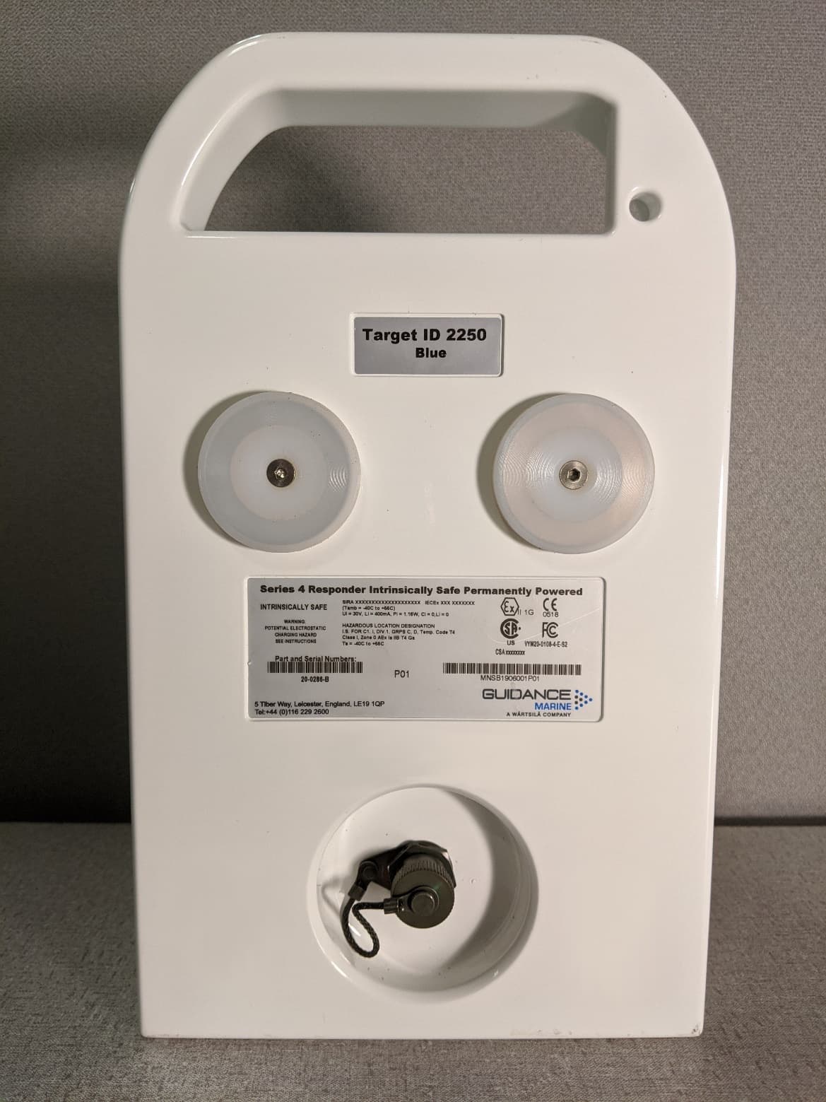
VYMRAD-1100
Sep 21, 2020SERIES 4 RESPONDER
Equipment Class
MRD - Marine Radar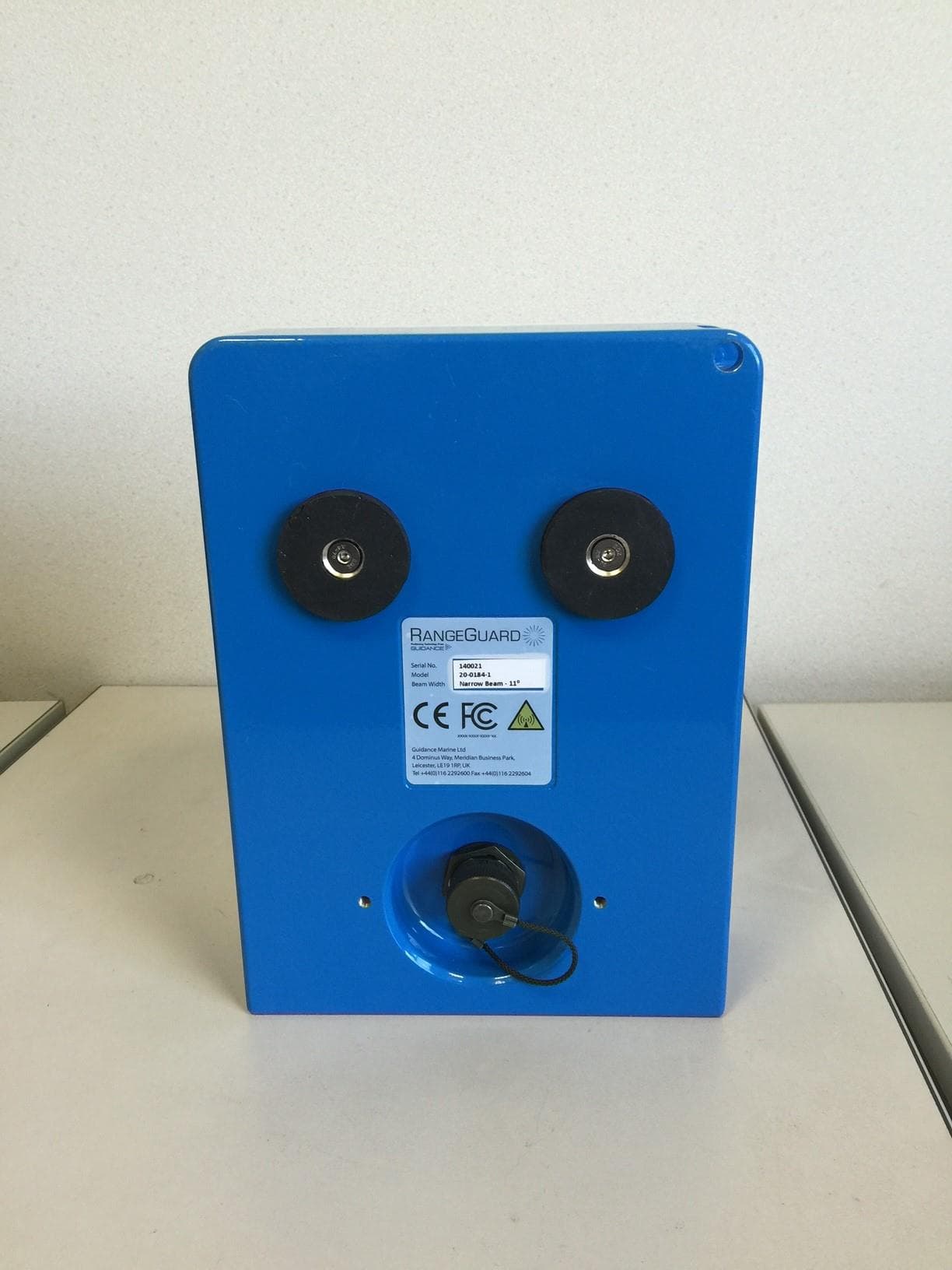
VYMRANGEGUARD
Jun 09, 2015RangeGuard Wide Beam 20-0183-1
Equipment Class
DXT - Part 15 Low Power Transceiver, Rx Verified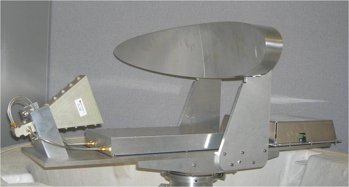
VYMRADASCAN
Mar 24, 2008RADASCAN
Equipment Class
MRD - Marine Radar