VYMRANGEGUARDRangeGuard Wide Beam 20-0183-1
Wartsila Guidance Marine Ltd.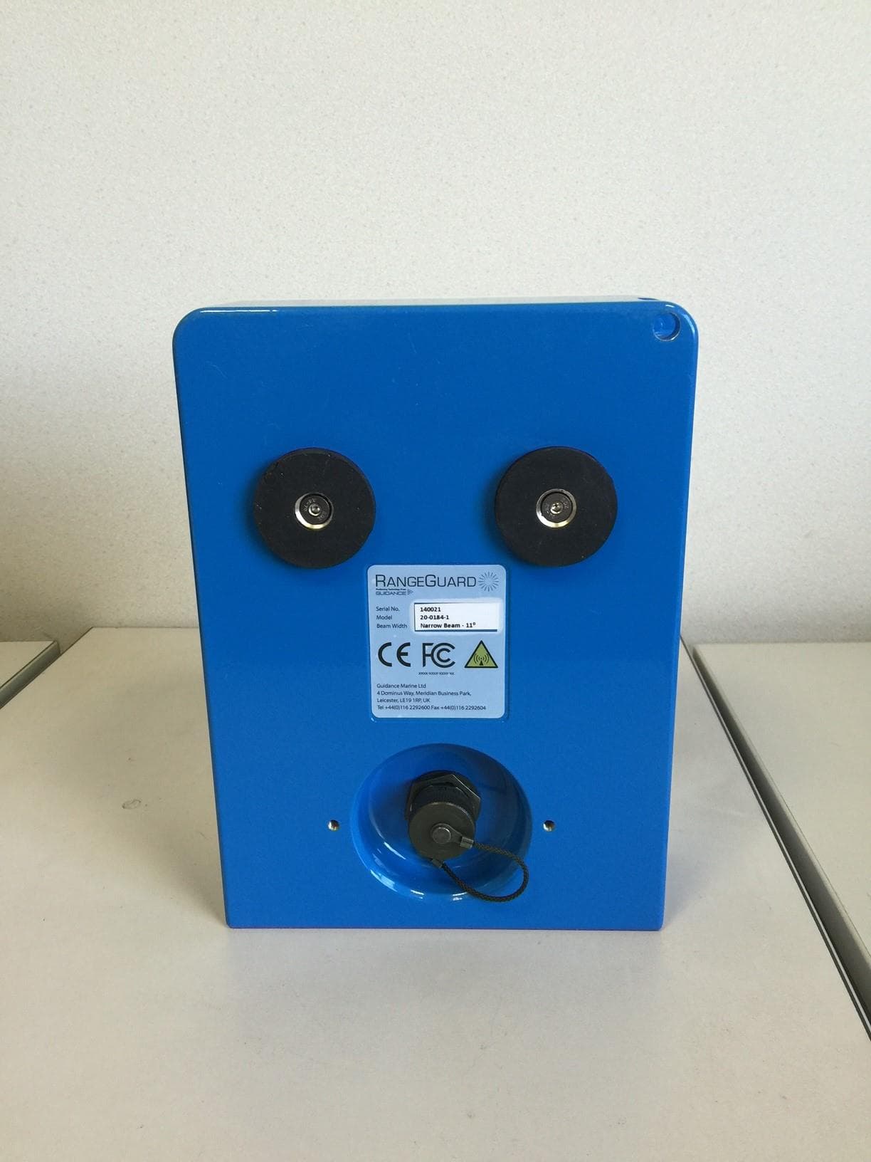
Click to zoom
Application Details
- Equipment Class
- DXT - Part 15 Low Power Transceiver, Rx Verified
- Date of Grant
- Jun 09, 2015
- Application Purpose
- Original Equipment
- Date of Application
- Jun 09, 2015
- Equipment Note
- RangeGuard Wide Beam 20-0183-1
- Frequency Range
- 24050.80000000 - 24249.40000000
- Country
- United Kingdom
Documents & Files
Document Text
Text extracted from the exhibit documents filed with the FCC. Open a document above to read the original.
Users Manual
Guidance Marine Ltd, 4 Dominus Way Meridian Business Park Leicester LE19 1RP UK Tel: +44 116 229 2600 Tel (Customer Services): +44 116 229 2665 Fax: +44 116 229 2604 Email: [email protected] Web: www.guidance.eu.com www.marine.direct Copyright © 2015 Guidance Marine Limited. All Rights Reserved. Copyright in the whole and every part of this document belongs to Guidance Marine Limited (the “Owner”) and may not be used, sold, transferred, copied or reproduced in whole or in part in any manner or form or in or on any media to any person other than in accordance with the terms of the Owner’s Agreement or otherwise without the prior written consent of the Owner.”Windows” is a trademark of Microsoft Corporation. All other brand or product names are trademarks or registered trademarks of their respective companies or organisations. Serial No: Date of Shipment from UK: Sensor Software Version:Software Version: Rangeguard Operator’s Guide Issue Date: 21/04/2015 Document No: 94-0447-4-A 0191 l 3 Document History Document NumberChangesIssue Date 94-0447-4-AFirst Release of Rangeguard Operator’s Guide21/04/2015 l 4 Introduction System Overview ......................................................................................................6 Getting Started Start Up and Shut Down ..........................................................................................8 Start Up..............................................................................................................................................8 Shut Down .........................................................................................................................................8 Screen Layout ..........................................................................................................9 Table View .......................................................................................................................................10 Display Options ......................................................................................................12 Selecting/Deselecting Sensors ..............................................................................13 Measurement Algorithms Selection of Measurement Algorithm .....................................................................15 Setting the Range Limits ........................................................................................16 Closest Algorithm ...................................................................................................17 Manual Threshold Algorithm ..................................................................................18 Max Peak Algorithm ...............................................................................................19 Peak Lock Algorithm ..............................................................................................20 Appendices System Specifications ............................................................................................22 FCC Warning Statement ........................................................................................23 Index .......................................................................................................................24 Table of Contents l 5 Introduction Welcome to the RangeGuard Operator’s Guide. It explains how to use the RangeGuard system once it has been fully installed. For instructions on how to install RangeGuard onto a vessel, refer to 94-0448-4 RangeGuard Installer’s Guide. The System Overview on page 6 describes the different components of the system and how they work together. The Getting Started section on page 8 explains how to get the system up and running and how to shut it down again. It also details what you will see on the RangeGuard Display screen when the system is running, and how to interpret the information. The Measurement Algorithms section on page 14 describes the different ways that RangeGuard can measure the distance to an object. Further useful information is included in the Appendices section on page 21. l 6 The RangeGuard system provides object detection and distance measurements using continuous wave radar sensors. These operate on a licence-exempt Short Range Device basis at 24.15GHz. The system comprises a control box, up to four sensors and a graphical user interface which can be accessed from any device connected to the same network. The sensors are typically positioned around the outside of a vessel and connected to the control box via standard Cat5e Ethernet cable up to a maximum length of 100m; longer cables can be made using cable with additional cores. The sensors have a fixed elevation beam width of 11° (+/-5.5°) and two options of azimuth beam: 11° (Narrow Beam) and 90° (Wide Beam). Each sensor measures the range to the nearest obstacle by default or to a selected obstacle if preferred. System Overview RangeGuard Display - the user interface - is run from a web browser. It is recommended that either the user interface supplied by Guidance Marine or else Google Chrome are used. Other browsers will work but without guarantee. Once the control box has been connected to the network, type its IP address (default 192.168.2.231) into the web browser address bar and the user interface will appear in Bird’s Eye View. l 7 Getting Started This section describes RangeGuard Display and basic use of the system. It contains the following pages: • Start Up and Shut Down (Page 8) • Screen Layout (Page 9) • Display Options (Page 12) l 8 Start Up and Shut Down Start Up To Open RangeGuard Display 1. Ensure that the control box is powered on. 2. Double-click on the RangeGuard icon. (Or run the RangeGuard Display application from: Start > All Programs > Guidance RangeGuard > RangeGuard Display). 3. The display will appear in full screen mode, with the Bird’s Eye View open. Shut Down To Close RangeGuard Display Click on the X button in the top right corner of the…
Text truncated - open the document above for the full version.
External Photos
Applicant: Guidance Marine Ltd FCC ID: VYMRANGEGUARD External Photos
Internal Photos
Applicant: Guidance Marine Ltd FCC ID: VYMRANGEGUARD Internal Photos
Test Report
REPORT ON THE EMC TESTING FOR GUIDANCE NAVIGATION LTD ON A RANGEGUARD DOCUMENT NO. TRA-025840-44-00A REPORT ON THE EMC TESTING OF A GUIDANCE NAVIGATION LTD RangeGuard WITH RESPECT TO SPECIFICATION FCC RULES CFR 47:2013 PART 15.107 AND 15.109 CLASS B TEST DATES:31/03/15 to 15/04/15 Written by: M.Baker Senior EMC Test Engineer Approved by: M.Leach EMC Product Manager Date: 16 th April 2015 Distribution: Copy 1: TRaC Global Ltd. Copy 2: GUIDANCE NAVIGATION LTD Disclaimers: [1] THIS DOCUMENT MAY BE REPRODUCED ONLY IN ITS ENTIRETY AND WITHOUT CHANGE [2] THE RESULTS CONTAINED IN THIS DOCUMENT RELATE ONLY TO THE ITEM(S) TESTED Report Number: TRA-025840-44-00A Issue: A Copy Number: PDF RF088 7.0 Report Number: TRA-025840-44-00A FRN: 0004994703 Page 3 of 29 1 Revision Record Issue Number Issue Date Revision History A 16/04/15 Original RF088 7.0 Report Number: TRA-025840-44-00A FRN: 0004994703 Page 4 of 29 2 Summary TEST REPORT NUMBER: TRA-025840-44-00A PURPOSE OF TEST: Electromagnetic Compatibility – Emissions TEST SPECIFICATION: FCC Rules CFR 47:2013 Part 15.107 and 15.109 Class B DEVIATIONS FROM SPECIFICATION: Not Applicable (refer to individual sections) EQUIPMENT UNDER TEST (EUT): RangeGuard EUT SERIAL NUMBER: 120023 EUT CATEGORY: Information Technology Equipment (ITE) TEST RESULT: Measured As Compliant Given any modifications stated in the relevant section of this report. MANUFACTURER/AGENT: Guidance Navigation Ltd ADDRESS: 4 Dominus Way Meridian Business Park Leicester LE19 1RP CLIENT CONTACT: Mr Tom Coggins 01162292624 [email protected] ORDER NUMBER: 255629 TEST DATES: 31/03/15 to 15/04/15 TESTED BY: M.Baker and Greg Ashe TRaC Global Ltd. RF088 7.0 Report Number: TRA-025840-44-00A FRN: 0004994703 Page 5 of 29 3 Contents 1 Revision Record ..................................................................................................................3 2 Summary .............................................................................................................................4 3 Contents ..............................................................................................................................5 4 Introduction ..........................................................................................................................6 5 Normative References .........................................................................................................7 6 Equipment Under Test ........................................................................................................8 6.1 EUT Identification .........................................................................................................8 6.2 System Equipment .......................................................................................................9 6.3 EUT Mode of Operation ...............................................................................................9 6.4 EUT Description ...........................................................................................................9 7 Block Diagram .................................................................................................................. 10 8 Test Standard Selection ................................................................................................... 11 8.1 Product Standard ...................................................................................................... 11 8.2 Basic Test Standard Selection .................................................................................. 11 9 Radiated Emissions as per ANSI C63.4:2003 ................................................................. 12 9.1 General ...................................................................................................................... 12 9.2 Radiated Emission Test Parameters ........................................................................ 12 9.3 EUT Test Results ...................................................................................................... 13 9.3.1 Radiated Emissions Test Data – 30MHz to 1GHz ............................................. 13 9.3.2 Radiated Emissions Test Data – 1GHz to 10GHz ............................................. 14 9.3.3 Radiated Emissions Test Data – 10GHz to 18GHz ........................................... 15 9.3.4 Radiated Emissions Test Data – 18GHz to 26.5GHz ........................................ 16 9.3.5 Radiated Emissions Test Data – 26.5GHz to 40GHz ........................................ 17 10 Sample Calculation ....................................................................................................... 18 11 Conducted Emissions as per ANSI C63.4:2003 ........................................................... 19 11.1 General .................................................................................................................. 19 11.2 Conducted Emission Test Parameters .................................................................. 19 11.3 EUT Test Results .................................................................................................. 20 11.3.1 Conducted Emissions Test Data ....................................................................... 20 12 Test Equipment List – TRaC Hull ................................................................................. 22 13 Test Equipment List – TRaC North West ..................................................................... 23 14 EMC Modifications ........................................................................................................ 25 15 Conclusion .................................................................................................................... 26 15.1 Conformity in Production ....................................................................................... 26 16 Measurement Uncertainty .....................................................................…
Text truncated - open the document above for the full version.
Test Report
A RADIO TEST REPORT FOR GUIDANCE NAVIGATION LIMITED ON RANGEGUARD SYSTEM DOCUMENT NO. TRA-025840-47-00A Total number of pages: 38 TRaC Wireless Test Report : TRA-025840-47-00A Applicant : Guidance Navigation Limited Apparatus : RangeGuard System Specification(s) : CFR47 Part 15 Purpose of Test : Certification FCCID : VYMRANGEGUARD Authorised by : : Radio Product Manager Issue Date :9 th June 2015 Authorised Copy Number : PDF TRaC Global Test Report: TRA-025840-47-00A 3 Contents Section 1: Introduction 4 1.1 General 4 1.2 Tests Requested By 5 1.3 Manufacturer 5 1.4 Apparatus Assessed 5 1.5 Test Result Summary 6 1.6 Notes Relating To The Assessment 7 1.7 Deviations from Test Standards 7 Section 2: Measurement Uncertainty 8 2.1 Measurement Uncertainty Values 8 Section 3: Modifications 10 3.1 Modifications Performed During Assessment 10 Section 4 General Test Procedures 11 4.1 Radiated Test Setup and Procedures 11 4.2 AC Powerline Conducted Emissions Test Setup and Procedures 12 4.3 Antenna Port Conducted Emissions 12 4.4 Power Supply Variation 13 4.5 Thermal Variation 13 4.6 Time Domain Measurements 13 Appendix A: Formal Emission Test Results 14 A1 Transmitter Intentional Emission Radiated 15 A2 Radiated Electric Field Emissions 16 A3 Power Line Conducted Emissions 19 Appendix B: Supporting Graphical Data 21 Appendix C: Additional Test and Sample Details 26 Appendix D: Additional Information 32 Appendix E: Calculation of the duty cycle correction factor 33 Appendix F: Photographs and Figures 34 TRaC Global Test Report: TRA-025840-47-00A 4 Section 1: Introduction 1.1 General This report contains an assessment of an apparatus against Electromagnetic Compatibility Standards based upon tests carried out on samples submitted to the Laboratory. Test performed by: TRaC Global [ ] Unit E South Orbital Trading Park Hedon Road Hull, HU9 1NJ. United Kingdom. Telephone: +44 (0) 1482 801801 Fax: +44 (0) 1482 801806 TRaC Global [X] Unit 1 Pendle Place Skelmersdale West Lancashire, WN8 9PN United Kingdom Telephone: +44 (0) 1695 556666 Fax: +44 (0) 1695 577077 Email: [email protected] Web site: http://www.tracglobal.com Tests performed by: D Winstanley Report author: D Winstanley This report must not be reproduced except in full without prior written permission from TRaC Global. TRaC Global Test Report: TRA-025840-47-00A 5 1.2 Tests Requested By This testing in this report was requested by : Guidance Navigation Limited 4 Dominus W ay Meridian Business Park Leicester LE19 1RP United Kingdom 1.3 Manufacturer As Above 1.4 Apparatus Assessed The following apparatus was assessed between 26 th – 27 th March 2015: Rangeguard System The Above device is a FMCW radar operating in the 24.00 – 24.25 GHz band TRaC Global Test Report: TRA-025840-47-00A 6 1.5 Test Result Summary Full details of test results are contained within Appendix A. The following table summarises the results of the assessment. The statements relating to compliance with the standards below apply ONLY as qualified in the notes and deviations stated in sections 1.6 to 1.7 of this test report. Full details of test results are contained within Appendix A. The following table summarises the results of the assessment. Test Type Title 47 of the CFR: Part 15 Subpart (c) Measurement standard Result Spurious Emissions Radiated <1000MHz 15.249 (a), (d) 15.209 ANSI C63.10:2009 Pass Spurious Emissions Radiated >1000MHz 15.249 (a), (d) 15.209 ANSI C63.10:2009 Pass AC Power conducted emissions 15.207 ANSI C63.10:2009 Pass Intentional Emission Frequency 15.249(a) ANSI C63.10:2009 Pass Intentional Emission Field Strength 15.249 (a) ANSI C63.10:2009 Pass Intentional Emission Band Occupancy 15.215C ANSI C63.10:2009 Pass Intentional Emission ERP (mW) - ANSI C63.10:2009 N/A Unintentional Radiated Spurious Emissions 15.109 ANSI C63.10:2009 N/A Extrapolation Factor: 15.31(f) - - Maximum Frequency of Search: 15.33 - - Antenna Arrangements Integral: 15.203 - - Antenna Arrangements External Connector: 15.204 - - Restricted Bands: 15.205 - - Abbreviations used in the above table: ANSI C 63.10:2009 is outside the scope of the laboratories UKAS accreditation. CFR : Code of Federal Regulations ANSI : American National Standards Institution REFE : Radiated Electric Field Emissions PLCE : Power Line Conducted Emissions TRaC Global Test Report: TRA-025840-47-00A 7 1.6 Notes Relating To The Assessment With regard to this assessment, the following points should be noted: The results contained in this report relate only to the items tested and were obtained in the period between the date of initial receipt of samples and the date of issue of the report. The apparatus was set up and exercised using the configurations, modes of operation and arrangements defined in this report only. Particular operating modes, apparatus monitoring methods and performance criteria required by the standards tested to have been performed except where identified in Section 1.7 of this test report (Deviations from Test Standards). For emissions testing, throughout this test report, “Pass” indicates that the results for the sample as tested were below the specified limit (refer also to Section 2, Measurement Uncertainty). Where relevant, the apparatus was only assessed using the monitoring methods and susceptibility criteria defined in this report. All testing with the exception of testing at the Open Area Test Site was performed under the following environmental conditions: Temperature : 17 to 23 °C Humidity : 45 to 75 % Barometric Pressure : 86 to 106 kPa All dates used in this report are in the format dd/mm/yy. This assessment has been performed in accordance with the requirements of ISO/IEC 17025. 1.7 Deviations from Test Standards There were no deviations from the standards tested to. TRaC Global Test Report: TRA-025840-47-00A 8 Section 2: Measurement Uncertainty 2.1 Measurement Uncertainty Values For the test data recorded the following measurement uncertainty was calculated: Radio Testing – General …
Text truncated - open the document above for the full version.
Contact Information
Applicant
Tom Coggins(General Manager, Engineering)
Test Firm
Element Materials Technology Warwick LtdStewart Barrowclough
Technical Specifications
| # | Rule Parts | Frequency Range | Power Output |
|---|---|---|---|
| 1 | 15C | 24.05 GHz - 24.25 GHz | - |
Other Applications from Wartsila Guidance Marine Ltd.
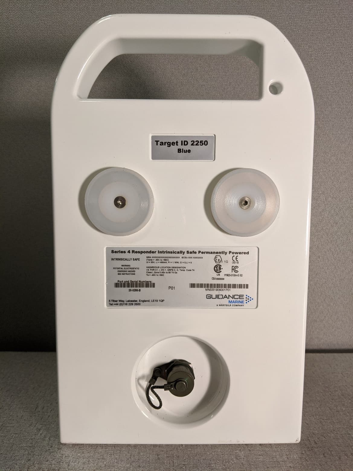
VYMRAD-1100
Sep 21, 2020SERIES 4 RESPONDER
Equipment Class
MRD - Marine Radar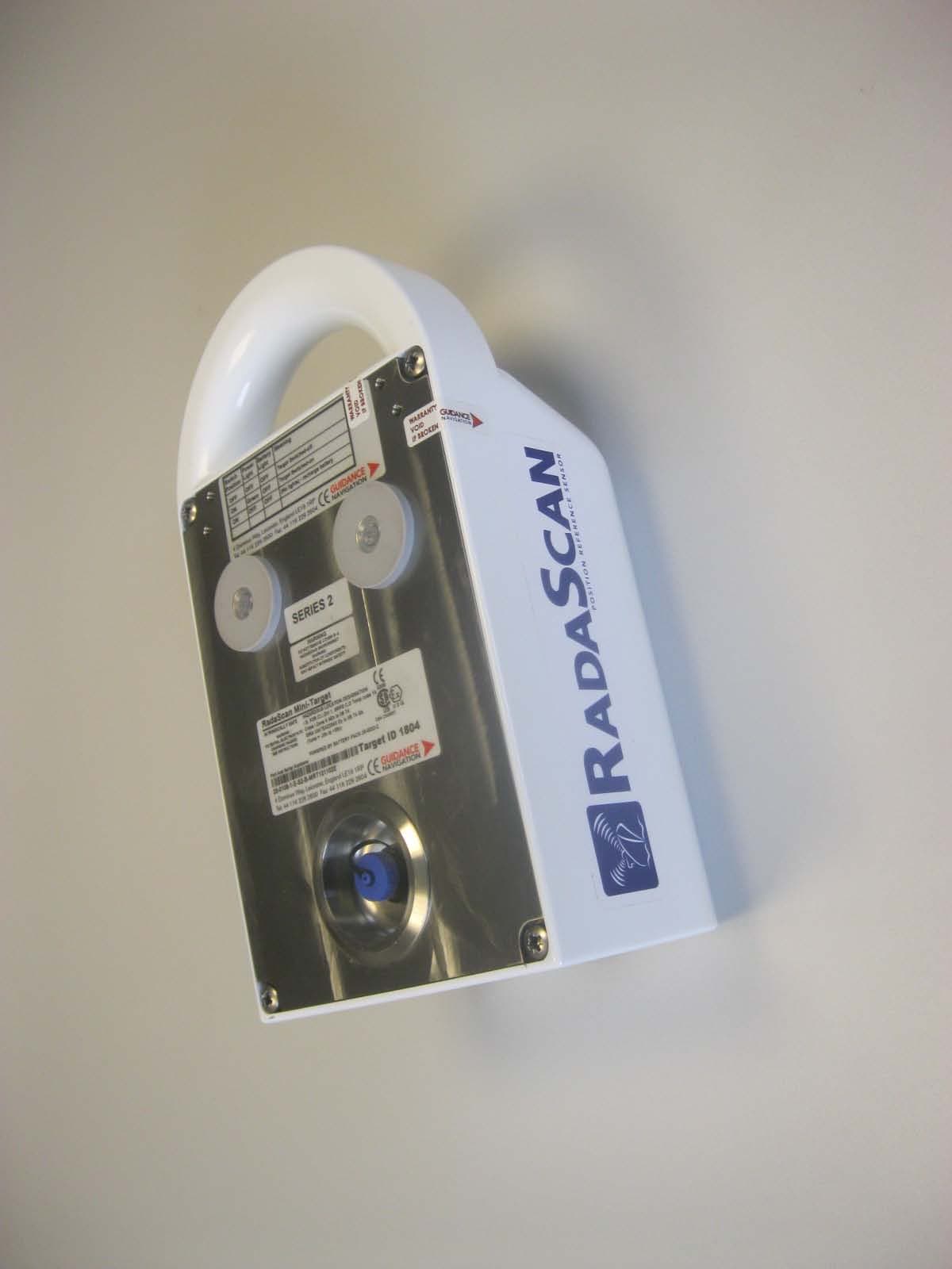
VYM20-0108-4-E-S2
Apr 22, 2013MINI RESPONDER
Equipment Class
MRD - Marine Radar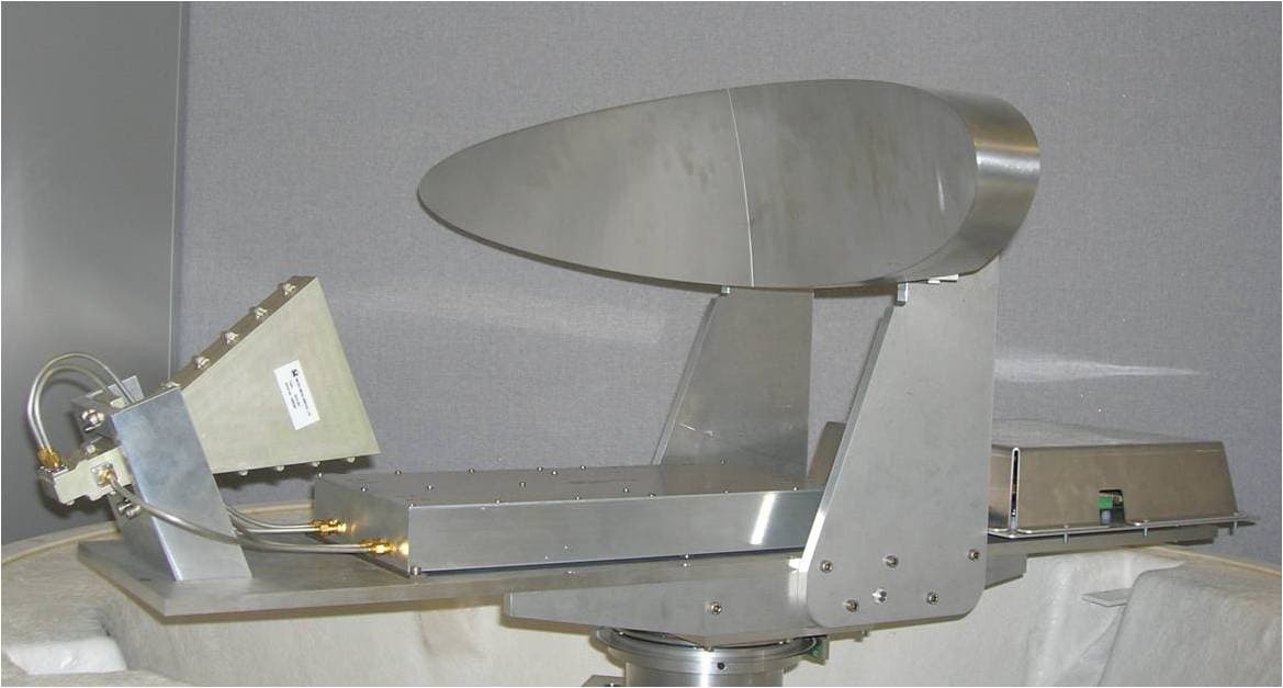
VYMRADASCAN
Mar 24, 2008RADASCAN
Equipment Class
MRD - Marine Radar