VYMRADASCANRADASCAN
Wartsila Guidance Marine Ltd.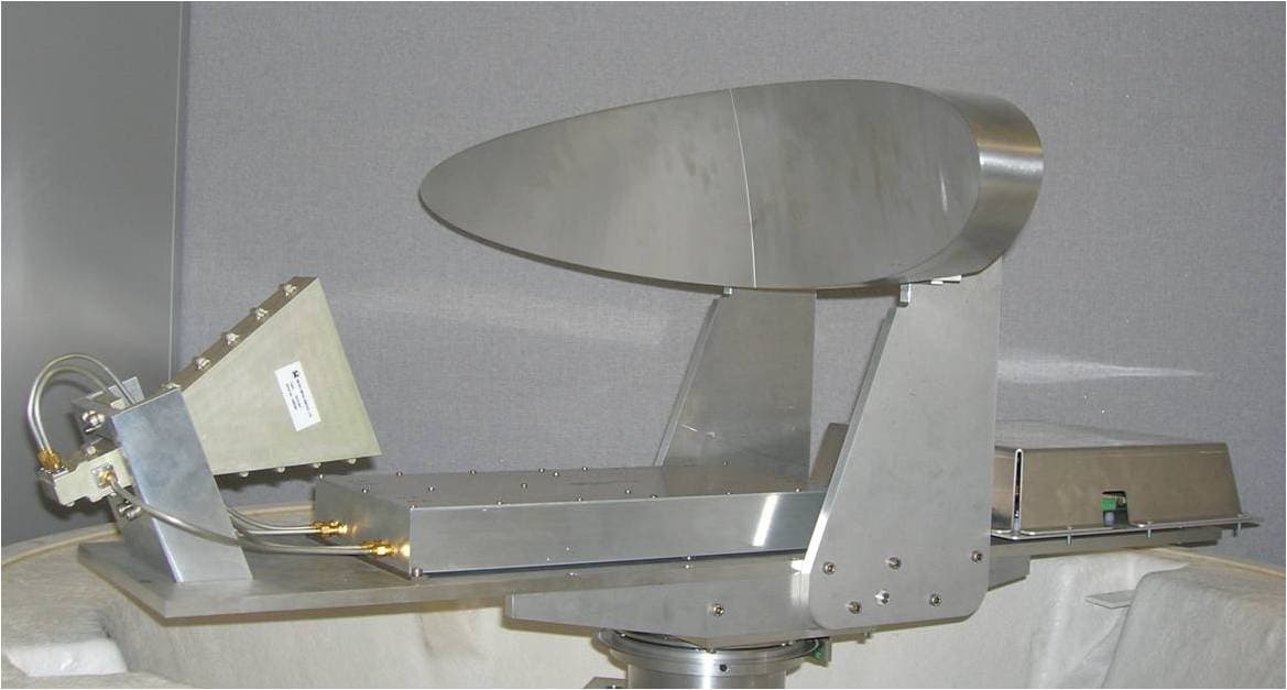
Click to zoom
Application Details
- Equipment Class
- MRD - Marine Radar
- Date of Grant
- Mar 24, 2008
- Application Purpose
- Original Equipment
- Date of Application
- Mar 19, 2008
- Equipment Note
- RADASCAN
- Frequency Range
- 9200.00000000 - 9300.00000000
- Country
- United Kingdom
Documents & Files
Document Text
Text extracted from the exhibit documents filed with the FCC. Open a document above to read the original.
Users Manual
Operator’s Guide Radascan Operators Manual 20/11/06 1:46 pm Page 1 Disk contains: • Control Console Software • Software License • Operator’s Guide Radascan Operators Manual 20/11/06 1:46 pm Page 2 RadaScan Operator - 1 Copyright © 2006 Guidance Navigation Limited. All Rights Reserved.Copyright in the whole and every part of this document belongs to GuidanceNavigation Limited (the “Owner”) and may not be used, sold, transferred,copied or reproduced in whole or in part in any manner or form or in or on anymedia to any person other than in accordance with the terms of the Owner’sagreement or otherwise without the prior written consent of the Owner.Wi ndows is a trademark of Microsoft Corporation. All other brand or product names are trademarks or registered trademarks oftheir respective companies or organisations.RadaScan is not currently approved for import to the United StatesGuidance Navigation Limited4 Dominus WayMeridian Business ParkLeicester LE19 1RPEnglandT el: +44 (0)116 229 2600 Fax: +44 (0)116 229 2604Email: [email protected] Release: 1.0bDate: 23/10/2006Document No: 94-0021-4Previous issue: No previous issue Design: www.birdhouse.co.uk Radascan Operators Manual 20/11/06 1:46 pm Page 1 ContentsIntroduction Components . . . . . . . . . . . . . . . . . . . . . . . . . . . . . . . . . . . . . . . . . . . . . .3Principles of Operation . . . . . . . . . . . . . . . . . . . . . . . . . . . . . . . . . . . . . .3 Serial numbers and software versions Software version information . . . . . . . . . . . . . . . . . . . . . . . . . . . . . . . . . .4 Using the system Startup . . . . . . . . . . . . . . . . . . . . . . . . . . . . . . . . . . . . . . . . . . . . . . . . . .5Suspend, exit or reset communications . . . . . . . . . . . . . . . . . . . . . . . . . .5Screen layout . . . . . . . . . . . . . . . . . . . . . . . . . . . . . . . . . . . . . . . . . . . . . .6Sensor display . . . . . . . . . . . . . . . . . . . . . . . . . . . . . . . . . . . . . . . . . . . . .7Button bar - display options . . . . . . . . . . . . . . . . . . . . . . . . . . . . . . . . . . .8Navigation section . . . . . . . . . . . . . . . . . . . . . . . . . . . . . . . . . . . . . . . . . .9Status bar . . . . . . . . . . . . . . . . . . . . . . . . . . . . . . . . . . . . . . . . . . . . . . .11Property pages . . . . . . . . . . . . . . . . . . . . . . . . . . . . . . . . . . . . . . . . . . .12Alarms property page . . . . . . . . . . . . . . . . . . . . . . . . . . . . . . . . . . . . . .13Using the historic alarm list . . . . . . . . . . . . . . . . . . . . . . . . . . . . . . . . . .14Reflection property page . . . . . . . . . . . . . . . . . . . . . . . . . . . . . . . . . . . .15Configuration property page . . . . . . . . . . . . . . . . . . . . . . . . . . . . . . . . .16DP feed format and message string . . . . . . . . . . . . . . . . . . . . . . . . . . . .17About property page . . . . . . . . . . . . . . . . . . . . . . . . . . . . . . . . . . . . . . .18Using the on-screen keyboard . . . . . . . . . . . . . . . . . . . . . . . . . . . . . . . .19Using log files . . . . . . . . . . . . . . . . . . . . . . . . . . . . . . . . . . . . . . . . . . . .20 Entering service access mode To obtain and use a temporary service access mode . . . . . . . . . . . . . . .21 The configuration page . . . . . . . . . . . . . . . . . . . . . . . . . . . . . . . . . . . . .22 Specifications Specification information . . . . . . . . . . . . . . . . . . . . . . . . . . . . . . . . . . . .23 RadaScan Operator - 2 Radascan Operators Manual 20/11/06 1:46 pm Page 2 RadaScan Operator - 3 We lcome to the RadaScan position reference sensor for dynamic positioning and other vessel control applications. RadaScan is a high accuracy radarbased sensor that provides positional information to allow automatedapproach and/or station keeping relative to a structure or vessel. Thestructure or vessel must be equipped with one or more retro-reflectiveRadaScan transponders/targets.Components:RadaScan has been designed for permanent installation and quick/easyoperation. A RadaScan system comprises of 3 major components as follows:• The RadaScan Sensor. A scanning transceiver unit with integral power supply and processing electronics for installation in a prominent external location in order to view available transponder. The Sensor is connected to the vessel DP system by a serial RS422 or Ethernet link. • The RadaScan Console. A system control and display application running under Microsoft Windows XP on a standard PC. This allows full control of the system together with graphical and data display of system status. An Ethernet link connects the Sensor to the Console PC. • RadaScan Transponder/Target.A passive self contained battery powered electronics module for temporary, semi-permanent or permanent installation on the target vessel. RadaScan transponders are ATEX certified as intrinsically safe. Principles of OperationThe RadaScan sensor emits a low power radar beam. The beam is receivedby a RadaScan transponder and instantaneously reflected back to the sensor.The sensor uses the reflection to accurately calculate the distance (range) anddirection (bearing) to the transponder. This positional data is automaticallysent to the DP system. The transponder reflection is retro-reflective incharacter (ie it is sent in the same direction as received beam). Thetransponder is also able to encode the reflection with a transponder identitycode. This code allows the sensor to recognise the reflection as genuine andso aid easy operation and improve tracking reliability. RadaScan unit RadaScan equipped vessel RadaScan transponders Introduction Radascan Operators Manual 20/11/06 1:46 pm Page 3 RadaScan Operator - 4 Component Part Numbers and individual Serial Number are assigned to eachsensor, transponder and PC. Software version informationThe Configuration page tab within the property sheet provides versioninformation about every software component with t…
Text truncated - open the document above for the full version.
Users Manual
Copyright © 2005 Guidance Navigation Limited. All Rights Reserved. Copyright in the whole and every part of this document belongs to Guidance Navigation Limited (the “Owner”) and may not be used, sold, transferred, copied or reproduced in whole or in part in any manner or form or in or on any media to any person other than in accordance with the terms of the Owner’s Agreement or otherwise without the prior written consent of the Owner. Windows is a trademark of Microsoft Corporation. All other brand or product names are trademarks or registered trademarks of their respective companies or organisations. Release: 1.0a Date: 25/06/06 Document No: 94-0015-4 Previous issue: Date: 25/06/06 Changes: New DP message types section & new connection diagrams Guidance Navigation Limited4 Dominus Way, Meridian Business Park,Leicester, LE19 1RP,England Tel: +44 (0)116 229 2600Fax: +44 (0)116 229 2604 Email: [email protected] RadaScan Installation Instructions RadaScan Sensor, PN 20-0067-0 Rev A Before starting an installation, please note the following important points: • All servicing / installation to be undertaken ONLY by qualified service personnel. There are no user serviceable parts inside the unit. • Do NOT plug in, turn on or attempt to operate an obviously damaged unit. • Replace fuses ONLY with the same type and rating as marked on the label adjacent to the fuse holder. • The equipment accepts the input 100-240Vac / 50-60Hz / 2.8 – 1.2A, as marked on the equipment. Ensure that the supply voltage available at the installation site meets the voltage range marking, as provided on the equipment. Contents Serial numbers and Software versions Software Version Information ............................... 3 Radascan Components Radascan system component layout ....................................... 4 Mechanical Installation Where to install Radascan ....................................... 5 How to install Radascan ....................................... 6 Unpacking the Radascan system ....................................... 6 Mounting the Radascan System ....................................... 6 Cable Installation Cable specifications ....................................... 7 Connecting the power cables ....................................... 7 Console and DP Feed Connections Console Connection ....................................... 8 DP Feed Connection ....................................... 8 Radascan Console Computer options Industrial PC Module ....................................... 9 Hatteland JH15 integrated monitor/CPU module ....................................... 10 Radascan Console set-up Entering Service Access mode ....................................... 12 Location offset ....................................... 13 Vessel name ....................................... 14 Additional shutdown menu features ....................................... 15 Initial log file creation ....................................... 16 Bearing Offset ....................................... 17 Operator training Aspects of Radascan and its use that should be described to a new user to complete the installation ....................................... 19 Technical notes Target types ....................................... 21 Target installation ....................................... 22 DP message types ....................................... 23 Low temperature operation ....................................... 25 Radascan Installer – 1 RadascanInstaller – 2 Serial numbers and software versions Component Part Numbers and individual Serial Numbers are assigned to each component of Radascan. These can be found on product labels affixed to each unit. These numbers identify the hardware configuration and product revision and will be requested by Guidance Navigation in the event of an application service or support call to the company. Software version information The Configuration page tab within the Property sheet provides version information about every software component within the Console application and the Radascan Sensor. Software component Version Information INSTALLER’S GUIDE RadascanInstaller – 3 Radascan Components Ethernet cable assembly RadascanInstaller – 4 Mechanical Installation Where to install Radascan The Radascan system is designed for permanent or semi-permanent installation at a suitable location on the installation vessel. Radascan sensor mounted on a rigid mounting surface, Above seal level, clear of obstructions and with a clear view in the direction of the targets The Radascan sensor should be firmly bolted to a flat horizontal surface at the suitable location The mounting surface must have the following characteristics: • be rigid and able to support the sensor weight of 75Kg. • be capable of receiving the 4 fixing bolts used to secure the sensor. • be well above sea level to prevent the swamping or immersion of the sensor. • afford an adequate view in the expected direction of retro-reflective targets. • be clear of likely omissions from exhausts or other particulate sources to prevent the need for overly frequent cleaning of the sensor Typical installation for a platform supply vessel is above the wheelhouse looking over the back deck area. Installation may benefit from the use of a custom fabricated mounting plate located outside the rear guard-rail RadascanInstaller – 5 How to install the Radascan System Unpacking the Radascan System The whole Radascan system is supplied and shipped in a custom-built crate, Use the following procedure to unpack and prepare the Radascan System. To unpack the Radascan System 1. Position the Radascan crate on a level surface, close to the area where the sensor will be installed. 2. Remove the top panel and then the side panels from the crate. 3. Remove the securing bolts (M12) from the base of the Radascan system. Mounting the Radascan Sensor To be specified RadascanInstaller – 6 Cable Installation The Radascan system is supplied without cables that ar…
Text truncated - open the document above for the full version.
Cover Letter(s)
Position Measurement ● Autonomous Vehicles ● Laser Scanners ● Sensor and Control Systems Guidance Navigation Limited 4 Dominus Way, Meridian Business Park, Leicester, LE19 1RP, UK Tel: 44 (0) 116 2292600 Fax: 44(0) 116 2292604 Company Registered in England No. 05231840 VAT No. GB 860 2032 65 Equipment Authorization Division Office of Engineering and Technology Federal Communications Commission 7435 Oakland Mills Road Columbia, MD 21046 21 January 2008 Ref: FCC ID: Request for Confidentiality Dear Sirs: With regard to the referenced application, Guidance Navigation Ltd, is requesting confidentiality of certain sections of the accompanying documents. The documents for which Guidance Navigation Ltd. is requesting confidentiality are: Schematic Diagram Block Diagram Operational Descriptions Parts List This request is made under the provisions of Section 0.457(d) of the Commission’s Rules, and Section 552(b)(4) of the Freedom of Information Act. The material for which confidentiality is requested falls within the scope of Section 552(b)(4) as trade secrets and includes material covered by Section 0.459 of the Commission’s Rules. Sincerely, Dr. Malcolm Roberts Managing Director
Cover Letter(s)
Position Measurement ● Autonomous Vehicles ● Laser Scanners ● Sensor and Control Systems Guidance Navigation Limited 4 Dominus Way Meridian Business Park Leicester LE19 1RP UK +44 (0)116 229 2600 +44 (0)116 229 2604 [email protected] www.guidance.eu.com Company Registered in England No. 05231840 VAT No. GB 860 2032 Telephone: Fax: Email: Website: Federal Communications Commission Authorization and Evaluation Division 1435 Oakland Mills Road Columbia, MD 21046 Date: 14 March 2008 SUBJECT: FCC Application for VYMRADASCAN To Whom It May Concern: We, the undersigned, hereby attest to the fact that we will apply the Declaration of Conformity procedure to the class B computer peripheral portion of this composite filing. Regards, Dr Malcolm Roberts Managing Director Guidance Navigation Ltd.
External Photos
APPLICANT: GUIDANCE NAVIGATION LIMITED FCC ID: VYMRADASCAN EXTERNAL PHOTOS
ID Label/Location Info
Position Measurement ● Autonomous Vehicles ● Laser Scanners ● Sensor and Control Systems Guidance Navigation Limited 4 Dominus Way Meridian Business Park Leicester LE19 1RP UK +44 (0)116 229 2600 +44 (0)116 229 2604 [email protected] www.guidance.eu.com Company Registered in England No. 05231840 VAT No. GB 860 2032 Telephone: Fax: Email: Website: RadaScan Sample Marking Plate Marking Plate Durability The marking plate is fixed to the outside of the RadaScan radome above the access hatch with a self adhesive tape. The marking plate is made of aluminum foil. The marking plate has been tested with isopropyl alcohol and a mechanical test as specified in ExTAG/67/CD. The marking is considered to be durable for the life of the product.
ID Label/Location Info
IDENTIFICATION LABEL Access Hatch OVERALL VIEW OF RadaScan SHOWING THE POSITION OF THE IDENTIFICATION LABEL IDENTIFICATION lABEL 26.02.2008 M McNulty Drawing NumberIssue Projection DateIssueAlterations Guidance Navigation Ltd Title Drawing Number Material : Specification : Treatment : Finish : Drawn By : Date : Drawing Size : Issue Drawing to BS 308 Machine Surfaces Marked Original Scale : Dimensions Linear : mm Angular : deg Surface Texture : um c Copyright Guidance Navigation Ltd 2006 A1 654321 A B C D E F 1:5 External: Otherwise Stated +/- 1 Internal: X X.X X.XX +0.25 -0 +0.10 -0 +0.05 -0 Tolerance Unless Angular : +0 -0.25 +0 -0.10 +0 -0.05
Internal Photos
APPLICANT: GUIDANCE NAVIGATION LIMITED FCC ID: VYMRADASCAN INTERNAL PHOTOS
Parts List/Tune Up Info
Position Measurement ● Autonomous Vehicles ● Laser Scanners ● Sensor and Control Systems Guidance Navigation Limited 4 Dominus Way Meridian Business Park Leicester LE19 1RP UK +44 (0)116 229 2600 +44 (0)116 229 2604 [email protected] www.guidance.eu.com Company Registered in England No. 05231840 VAT No. GB 860 2032 Telephone: Fax: Email: Website: RadaScan RF Frequency Tuning Procedure From RadaScan Transceiver production calibration document: CMR-1091 Issue 1, Test Procedure for CMD100414 GN Transceiver , I Weller, Oct 2006 . 3.3 YIG Drive Tuning The YIG frequency may be monitored by tapping into the LO breakthrough of the mixer by attaching a counter either to the Receiver input connector Rx_sk1 or to the IF output Rx_sk4 via a suitable adaptor. Wait until the Transceiver has been powered up for a period of 10 minutes. Set the switch on the Test Facility to ‘Set’. This turns off any ramp input to the Transceiver. The switch labelled Max and Min toggles the ramp to the Transceiver between 255 and 0. Switch the frequency between Max and Min repeatedly at approximately 0.5 second intervals. It is necessary to do this so that the temperature of the YIG is stabilised between the two settings. Whilst monitoring the frequency of the YIG at the two settings using the frequency counter, adjust potentiometer R43 on the IF board so that the difference between them is as close to 100MHz as possible. With a little practice this can be achieved to an accuracy of ± 50kHz. Once this has been done, adjust potentiometer R40 on the IF board so that the maximum and minimum frequencies are 9.3HGz and 9.2GHz respectively. Check the frequency deviation once again. Record the maximum frequency, minimum frequency and frequency deviation on the test sheet.
Test Report
849 NW STATE ROAD 45 NEWBERRY, FL 32669 USA PH: 888.472.2424 OR 352.472.5500 FAX: 352.472.2030 EMAIL: [email protected] HTTP://WWW.TIMCOENGR.COM FCC PART 80 TEST REPORT APPLICANT GUIDANCE NAVIGATION 4 DOMINUS WAY MERIDAN BUSINESS PARK LEICESTER, LE19 1RP UK FCC ID VYMRADASCAN MODEL NUMBER RADASCAN PRODUCT DESCRIPTION NAVIGATION RADAR DATE SAMPLE RECEIVED 1/04/2008 DATE TESTED 1/16/2008 TESTED BY NAM NGUYEN APPROVED BY MARIO DE ARANZETA TIMCO REPORT NO. 26UT8TestReport.doc TEST RESULTS PASS FAIL THE ATTACHED REPORT SHALL NOT BE REPRODUCED EXCEPT IN FULL WITHOUT THE WRITTEN APPROVAL OF TIMCO ENGINEERING, INC. Test Certificate # 0955-01 Applicant: GUIDANCE NAVIGATION LTD. FCC ID: VYMRADASCAN Report: G\GUIDANCE\26UT8\26UT8TestReport.doc Page 2 of 13 TABLE OF CONTENTS GENERAL REMARKS................................................................................................. 3 GENERAL INFORMATION .......................................................................................... 4 EQUIPMENT LIST ...................................................................................................... 5 TEST PROCEDURE ................................................................................................... 6 RF POWER OUTPUT .................................................................................................. 7 MODULATION CHARACTERISTICS............................................................................ 8 FIELD STRENGTH OF SPURIOUS EMISSIONS......................................................... 12 FREQUENCY STABILITY.......................................................................................... 13 Applicant: GUIDANCE NAVIGATION LTD. FCC ID: VYMRADASCAN Report: G\GUIDANCE\26UT8\26UT8TestReport.doc Page 3 of 13 GENERAL REMARKS The attached report shall not be reproduced except in full without the written permission of Timco Engineering Inc. The test results relate only to the items tested. Summary The device under test does: fulfill the general approval requirements as identified in this test report not fulfill the general approval requirements as identified in this test report Attestations This equipment has been tested in accordance with the standards identified in this test report. To the best of my knowledge and belief, these tests were performed using the measurement procedures described in this report. All instrumentation and accessories used to test products for compliance to the indicated standards are calibrated regularly in accordance with ISO 17025 requirements. Testing Certificate # 0955-01 I attest that the necessary measurements were made, under my supervision, at: Timco Engineering Inc. 849 NW State Road 45 Newberry, Fl 32669 Authorized Signatory Name: Mario de Aranzeta C.E.T. Compliance Engineer/ Lab. Supervisor Date: 2/7/08 Applicant: GUIDANCE NAVIGATION LTD. FCC ID: VYMRADASCAN Report: G\GUIDANCE\26UT8\26UT8TestReport.doc Page 4 of 13 GENERAL INFORMATION DUT Specification DUT Description NAVIGATION RADAR FCC ID VYMRADASCAN Model Number RADASCAN Serial Number N/A Operating Frequency 9.2-9.3 GHz No. of Channels Single Type of Emission Swept CW Modulation FM 110–120Vac/50– 60Hz DC Power (24 Vdc) DUT Power Source Battery Operated Exclusively Prototype Pre-Production Test Item Production Fixed Mobile Type of Equipment Portable Antenna narrow beamwidth parabolic reflector 28 dBi gain Antenna Connector SMA Test facility Timco Engineering, Inc. 849 NW State Road 45, Newberry, FL 32669 Test Condition The DUT was tested in the laboratory in an environment with normal temperature and humidity. The temperature was 26ºC with a relative humidity of 50%. Modifications None Test Exercise The DUT was placed in continuous transmit mode of operation Applicable Standards ANSI/TIA 603-C;2004 , FCC CFR 47 Part 90 Applicant: GUIDANCE NAVIGATION LTD. FCC ID: VYMRADASCAN Report: G\GUIDANCE\26UT8\26UT8TestReport.doc Page 5 of 13 EQUIPMENT LIST Device Manufacturer Model Serial Number Cal/Char Date Due Date 3/10-Meter OATS TEI N/A N/A Listed 3/20/07 3/19/10 3-Meter OATS TEI N/A N/A Listed 1/11/06 1/10/09 3-Meter Semi- Anechoic Chamber Panashield N/A N/A Listed 5/11/07 5/10/10 Analyzer Tan Tower Spectrum Analyzer HP 8566B Opt 462 3138A07786 3144A20661 CAL 11/30/07 11/30/09 Analyzer Tan Tower RF Preselector HP 85685A 3221A01400 CAL 11/30/07 11/30/09 Analyzer Tan Tower Quasi-Peak Adapter HP 85650A 3303A01690 CAL 11/30/07 11/30/09 Analyzer Tan Tower Preamplifier HP 8449B- H02 3008A00372 CAL 11/30/07 11/30/09 Antenna: Biconnical Electro- Metrics BIA-25 1171 CAL 7/18/07 7/18/09 Antenna: Log- Periodic Electro- Metrics LPA-25 1122 CAL 12/1/06 12/1/08 Antenna: Double- Ridged Horn Electro- Metrics RGA-180 2319 CAL 7/18/07 7/18/09 LISN Electro- Metrics ANS-25/2 2604 CAL 10/5/06 10/5/08 Termaline Wattmeter Bird Electronic Corporation 611 16405 CAL 3/15/07 3/15/09 Applicant: GUIDANCE NAVIGATION LTD. FCC ID: VYMRADASCAN Report: G\GUIDANCE\26UT8\26UT8TestReport.doc Page 6 of 13 TEST PROCEDURE Power Line Conducted Interference: The procedure used was ANSI/TIA 603-C:2004 using a 50uH LISN. Both lines were observed with the UUT transmitting. The bandwidth of the spectrum analyzer was 10 kHz with an appropriate sweep speed. Bandwidth 20 dB: The measurements were made with the spectrum analyzer's resolution bandwidth (RBW) = 1 MHz and the video bandwidth (VBW) = 3 MHz and the span set as shown on plot. Power Output: The RF power output was measured at the antenna feed point using a peak power meter. Antenna Conducted Emissions: The RBW = 100 kHz, VBW = 300 kHz and the span set to 10.0 MHz and the spectrum was scanned from 30 MHz to the 10 th Harmonic of the fundamental. Above 1 GHz the resolution bandwidth was 1 MHz and the VBW = 3 MHz and the span to 50 MHz. Radiation Interference: The test procedure used was ANSI/TIA 603-C:2004 using an Agilent spectrum receiver with pre-selector. The bandwidth (RBW) of the spectrum receiver was 100 kHz up to 1 GHz and 1 MHz above 1 GHz …
Text truncated - open the document above for the full version.
Contact Information
Applicant
Tom Coggins(General Manager, Engineering)
Test Firm
Timco Engineering, Inc.Bruno Clavier
Technical Specifications
| # | Rule Parts | Frequency Range | Power Output | Emission | Tolerance |
|---|---|---|---|---|---|
| 1 | 80 | 9.20 GHz - 9.30 GHz | 1 W | 100MF0N | 0.2000000000 % |
Other Applications from Wartsila Guidance Marine Ltd.
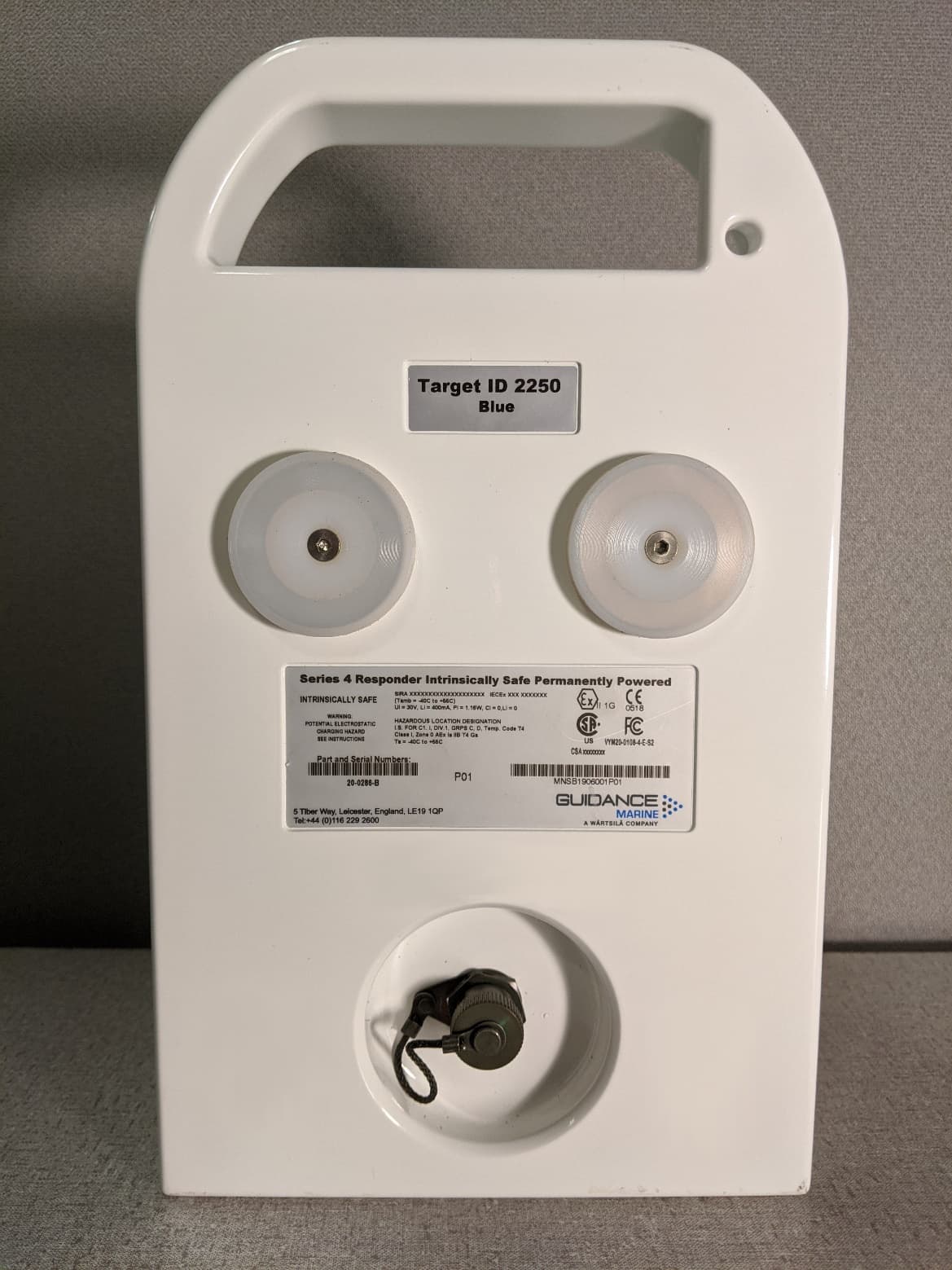
VYMRAD-1100
Sep 21, 2020SERIES 4 RESPONDER
Equipment Class
MRD - Marine Radar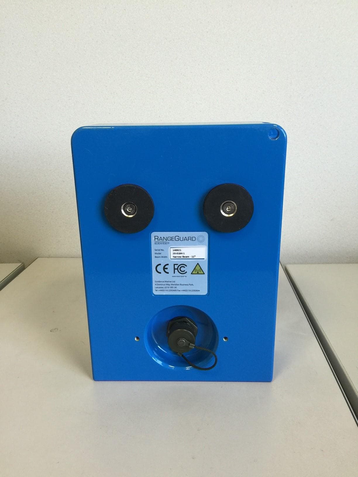
VYMRANGEGUARD
Jun 09, 2015RangeGuard Wide Beam 20-0183-1
Equipment Class
DXT - Part 15 Low Power Transceiver, Rx Verified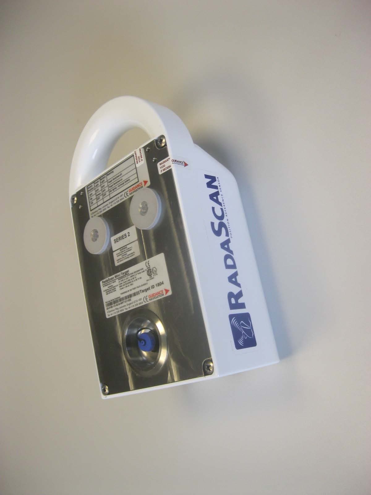
VYM20-0108-4-E-S2
Apr 22, 2013MINI RESPONDER
Equipment Class
MRD - Marine Radar