W6Y-AP200ACCESS POINT
PASSTECH CO., LTD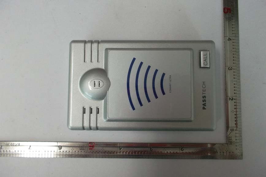
Click to zoom
Application Details
- Equipment Class
- DTS - Digital Transmission System
- Date of Grant
- Dec 04, 2013
- Application Purpose
- Original Equipment
- Date of Application
- Dec 04, 2013
- Equipment Note
- ACCESS POINT
- Frequency Range
- 2405.00000000 - 2480.00000000
- Company
- PASSTECH CO., LTD
- Country
- South Korea
Documents & Files
Document Text
Text extracted from the exhibit documents filed with the FCC. Open a document above to read the original.
Users Manual
http://www.esmartlock.com ESMART ULTRA SETUP MANUAL (AP200_Ethernet Setting) 2012/9/9 e-Smart Lock 1-1. AP200 TEST 준비 DC JACK POWER/COM 1. AP200 TEST & SETUP 구성품 DC JACK RJ11 D-SUB 9P(FEMALE) DIP SWITCH (RJ11) ETHERNETR [ POWER/COM CABLE ] [ AP200 TERMINAL ] RJ11 (RJ45) [ POWER CABLE ] USB DC PLUG USB [ DC POWER ADAPTOR - 12 V ] [ USB TO 232 CABLE ] D-SUB 9P (MALE) [ LAN CABLE_CROSS ] Page 2 e-Smart Lock 1-2. AP200 TEST 준비 DC JACK D-SUB 9P(FEMALE) 2. AP200 TEST 설치구성도 [ DIRECT LAN CABLE ] ETHERNET 통신 RS 232 통신 [ USB TO 232 CABLE ] PC (SERVER or CLIENT) DC 12 V 공급 전원 ON (RED LED ON) [ DC ADAPTOR_ 12 V ] RESET 버튼 ( 전원재부팅 ) Page 3 [ AP200 ] e-Smart Lock 1-3. AP200 TEST 준비 DC JACK D-SUB 9P (FEMA E) 1) USB TO 232 CABLE 연결 : PC USB 단자에 USB TO 232 CABLE 을연결하고 , PC 장치관리자에서생성된 COM PORT NO. 를확인한다 . 2. AP200 TEST 설치순서 (FEMA L E) , 2) POWER/COM CABLE 연결 : USB TO 232 CABLE 의 D-SUB 9P(MALE) 과 POWER/COM CABLE(FEMALE) 을연결한다 . 3) DC ADAPTOR-5V 연결 : DC ADAPTOR -5V 의 DC PLUG 를 POWER/COM CABLE 의 DC JACK 에연결한다 . 4) DIRECT LAN CABLE 연결 : PC 의 ETHERNET PORT 와 AP200 TERMINAL ETHERNET PORT(RJ45) 을연결한다 . 5) AP200 TERMINAL 연결 : POWER/COM CABLE 의 RJ11 을 AP TERMINAL 의 RJ11 삽입부분에연결한다 . Î 정상 (LED RED ON) ( 주의 : RJ45 부분에삽입할경우회로손상및열로인한화재발생가능성있음 ) 6) DIP SWITCH 역할 (AP TERMINAL) 6) DIP SWITCH 역할 (AP TERMINAL) (1) WIFI & AP SETUP MODE : 4 번 (ON) / 1,2,3,5,6 번 (OFF) Î WIFI 혹은 AP SETUP 시사용하는모드 (2) WIFI OPERATION MODE ON : 1 번 (ON) / 2,3,4,5,6 번 (OFF) Î A P 와 SERVER 간의통신을 WIFI 로사용하는모드 (3) ETHERNET OPERATION MODE : 2 번 (ON) / 1,3,4,5,6 번 (OFF) Î AP 와 SERVER 간의통신을 ETHERNET 으로사용하는모드 (4) DEBUG MODE < DIP SWITCH > ON OFF Page 4 : 3 번 (ON) / 1,2,4,5,6, 번 (OFF) Î AP200 TERMINAL 의통신상태를확인하는모드 < DIP SWITCH > e-Smart Lock 2-1. AP200 ETHERNET 통신 TEST 1. 준비작업 1) 1-2 과같이정상적으로연결한다 2) AP200 의 DIP SWITCH 는 1,2,3,4,5,6 전부 OFF 한다 . 2. ETHERNET 접속정상여부확인 1) 접속불량인경우 : PC 의 네트웍아이콘에 [ X ] 라고표시되어있음 2) 접속 정상인 경우 :PC 의 네트웍 아이콘에 [!] 라고 표시 되어 있음 [ 접속불량 ] [ 접속 정상 ] 2) 접속 정상인 경우 : PC 의 네트웍 아이콘에 [ ! ] 라고 표시 되어 있음 3. AP200 ETHERNET MODULE 접속여부확인 [ 접속 정상 ] 1) PC 의 네트웍아이콘이 [ ! ] 라고표시되어있는상태확인 2) WIZ100SR CONFIG TOOL 3.0.2 프로그램실행 3) CONFIG TOOL 에서 [SEARCH] 아이콘실행 4) 좌측그림과같이 MAC ADDRESS & IP ADDRESS 상태값표시됨 ①불량인경우 - 상태값이 DISPLAY 되지않음 ( 네트웍상태및연결상태확인하여상태값이 DISPLAY 될때까지재시도 ) ②정상인경우 - 상태값이좌측그림과같이표시됨 [ WIZ100SR CONFIG TOOL 3 0 2 ] Page 5 [ WIZ100SR CONFIG TOOL 3 . 0 . 2 ] e-Smart Lock 2-2. AP200 ETHERNET 통신 TEST 4. PC 상의 IP Address & Subnet Mask 확인 ( 좌측그림참고 ) 1) PC 의 COMMAND WINDOW 에서 [ CMD ] 작성하여 [ 확인 ] 클릭 . 2) 화면에서 [ ipconfig ] 라고작성 3 ) Enter 하면 A P Adress & Subnet Mask 확인가능함 ) 5. AP200 의 IP Address & Subnet Mask 확인 ( 아래그림참고 ) 1) WIZ100SR CONFIG TOOL 3.0.2 실행 . 2) ① [ SEARCH ] 클릭하여상태값이표시되는지확인 ) 의 ② &S 설정 3 ) AP200 의 ② Local IP & S ubnet 설정 - Local IP : 해당 PC 의 IP Address 의마지막값만변경하여설정 (EX : 192.168.0.134) - Subnet Mask : 해당 PC 의 Subnet Mask 와동일하게설정 (EX:255.255.0.0) - PORT : [ 5000 ] 으로그대로설정 4) ③ Operation Mode : [ Mixed ] 설정 5) ④ [ Setting ] 클릭하여저장함 Î 반드시 PC 화면우측하단의네트웍아이콘이 [ ! ] 나타날때까지기다림 [ PC 의 IP Adress & Subnet Mask 확인 ] ② ③ Page 6 ① [ AP200 의 IP Adress & Subnet 설정 ] ④ e-Smart Lock 2-3. AP200 ETHERNET 통신 TEST 7. AP200 준비작업 1) 1-3 과같이정상적으로연결 2) AP200 의 DIP SWITCH 는 2 번 ,3 번 ON 하고 1,4,5,6 번 OFF . 3) AP200 전원 재부팅 :5VDCJACK 재삽입 or RESET 버튼 누름 [ 접속불량 ] [ 접속정상 ] 8. Device Terminal V1.0 TEST (AP200 통신정상여부확인 ) 3) AP200 전원 재부팅 : 5V DC JACK 재삽입 or RESET 버튼 누름 4) 네트웍상태확인 : 접속정상인 [ ! ] 표시되어있는지확인 [ ] 1) Device Terminal V1.0 실행 . 2) Serial Communication 설정 : Serial Config 설정하고 [Open] 클릭 ① Serial Port : USB TO 232 CABLE 연결된 Serial Port ② Baud Rate : 115200 ③ Data Bit : 8BIT / Stop Bit : 1 / Parity : None / Flow Control : None 3) Network Communition 설정 : Network Config 설정하고 [ Connect ] 클릭 정상연결상태 : Network Config 설정하고 [ Connect ] 클릭 ① IP Address : AP200 의 ETHERNET IP ADDRESS 와동일하게설정 ② PORT : AP200 의 PORT 와동일하게설정 4) AP200 통신정상여부확인 ① Network Communication 의 [1234] 작성 ① Network Communication 의 [1234] 작성 ② [Send] 클릭하면 Serial Communition Window 에 [1234] 라고표시됨 불량인경우 : 1234 표시되지않음 ( 네트웍상태및기타연결상태확인하여 DISPLAY 될때까지재시도 ) [ Device Terminal V1 0 프로그램 화면 ] 1234 Page 7 [ Device Terminal V1 . 0 프로그램 화면 ] e-Smart Lock 3-1. SERVER & AP200 통신 TEST 1. SERVER & AP200 통신 TEST 설치구성도 DC JACK D-SUB 9P(FEMALE) ETHERNET 통신 인터넷 ETHERNET 통신 RS 232 통신 [ USB TO 232 CABLE ] DC 12 V 공급 PC (SERVER or CLIENT) [ AP200 ] Page 8 [ DC ADAPTOR_ 12 V ] e-Smart Lock 3-2. SERVER & AP200 통신 TEST 1. SERVER PC TCP/IP 설정상태확인 1) 3-1 과같이정상적으로연결한다 . 2) PC 의 COMMAND WINDOW 에서 [ CMD ] 작성하여 [ 확인 ] 클릭 . 3) 화면에서 [ ipconfig ] 라고작성 4) Enter 하면 AP Address & Subnet Mask 확인가능함 EX> - IP Address : 192.168.0.7- Subnet Mask : 255.255.255.0- Gateway : 192.168.0.1 Page 9 e-Smart Lock 3-3. SERVER & AP200 통신 TEST ② 2. AP200 ETHERNET_ Network 설정 1) AP200 설정 : DIP Switch 1,2,3,4,5,6 번 (OFF) 2) WIZ100SR Config Tool 프로그램실행 ② ③④ ⑤ 3) ① [Search] 를클릭 : 같은 LAN 상에존재하는모든 AP200 ETHERNET MODULE 을 검색하며 , Board List 에 Mac Address 표시됨 4) ② Enable Serial Debuge Mode : [ V ] 체크함 . 5) ③ Board List : AP200 Ethernet Module (WIZ00SR) 의 MAC Address 표시함 ⑤ ⑥ 5) ③ Board List : AP200 Ethernet Module (WIZ00SR) 의 MAC Address 표시함 6) ④ IP Config Method : [ Static ] 설정 7) ⑤ Ethernet Module (WIZ100SR) 의 Network 설정 - Local IP/Port : 연결가능한할당된 WIZ100SR 의 IP Address 와 Port 번호 ① ⑧ ⑦ - Subnet : WIZ100SR 의 Subnet Mask - Gateway : WIZ100SR 의 Gateway Address ※주의사항 Local IP, Subnet Mask, Gateway 정보가불명확한경우 , 반드시네트워크 관리자에게문의하여정확한정보를기입해야합니다 . 잘못된정보를기입하면 IP 충돌이발생하거나네트워크동작이불가할수 있으니주의해야합니다 . 8 ) ⑥ Server IP/Port : Server PC IP Address 확 인 하여 IP Address & Port 설 정 < NETWORK 설정화면 > ) ⑥ 확하여 정 - Server IP : 192.168.0.17- Port : 2274 9) ⑦ Operation Mode : [ Client ] 설정 , WIZ100SR 이미리설정된서버주소로 TCP 연결을 시도하는 모드이며 연결된후 양방향 통신 Page 10 TCP 연결을 시도하는 모드이며 , 연결된후 양방향 통신 10) ⑧ [Setting] 을클릭 : Network Config 설정값을저장 e-Smart Lock 3-4. SERVER & AP200 통신 TEST 3. AP200 ETHERNET_ Serial 설정 1) ① [Search] 를클릭 : 같은 LAN 상에존재하는모든 AP200 ETHERNET MODULE 을 검색함 . Board List 에 Mac Address 표시됨 2) ② Serial Config 설정 ② 2) ② Serial Config 설정 - Speed : 115200- Databit : 8- Parity : None ①③ - Stop Bit : 1- Flow : None 3) ③ [Setting] 을클…
Text truncated - open the document above for the full version.
Cover Letter(s)
PASSTECH CO., Ltd. No. 1305, Kranz Techno, 388, Dunchon-daero, Jungwon-gu, Seongnam-si, Gyeonggi-do, Korea Tel: +82-31-743-7277 Fax: +82-31-743-7276 LETTER OF AUTHORIZATION To whom it may concern: We, the undersigned, hereby authorize Korea Standard Quality Laboratories, to act on our behalf in all manners relating to application for equipment authorization for FCC ID: W6Y-AP200. including signing of all documents relating to these matters. Any and all acts carried out by Korea Standard Quality Laboratories, on our behalf shall have the same affect as acts of our own. This authorization is valid until further written notice from PASSTECH CO., Ltd. Korea Standard Quality Laboratories (Contact Person) Contact name: Soon Ho, Kim Position: Manager Phone:+82-31-356-7333 E-mail: [email protected] Date : December 04, 2013 Sincerely, Hyung-Mo, Park / Managing Diretor Company name: PASSTECH CO., Ltd. Phone: +82-31-743-7277 Fax: +82-31-743-7276 E-mail: [email protected]
Cover Letter(s)
FCC, Request for non-disclosure Date: November 13, 2013 Page 1 of 1 PASSTECH CO., Ltd. No. 1305, Kranz Techno, 388, Dunchon-daero, Jungwon-gu, Seongnam-si, Gyeonggi-do, Korea Subject: Request for confidentiality FCC ID: W6Y-AP200 Gentlemen: Pursuant to Sections 0.457 and 0.459 of the Commission's Rules, we hereby request confidential treatment of information accompanying this application as outlined below: ☑ Block Diagrams ☑ Operational Description ☑ Schematic Diagrams the above materials contain trade secrets and pr oprietary information not customarily released to the public. The public disclosure of these materials may be harmful to the applicant and provide unjustified benefits to its competitors. The applicant understands that pursuant to Section 0.457 of the Rules, disclosure of this application and all accompanying documentation will not be made before the date of the Grant for this application. <Date> November 13, 2013 <City> Seongnam-si <Name and signature of applicant> Hyung-Mo, Park / Managing Diretor
Cover Letter(s)
PASSTECH CO., Ltd. No. 1305, Kranz Techno, 388, Dunchon-daero, Jungwon-gu, Seongnam-si, Gyeonggi-do, Korea November 13, 2013 Subject: DoC declaration To Whom it may concern, We, as the grantee of this project FCC ID: W6Y-AP200, would like to declare that the composite portion categorized as computer peripheral has been authorized under the Declaration of Conformity procedures. Test Laboratory : Korea Standard Quality Laboratories #102, Jangduk Dong, Hwasung City, Kyunggi Do, South Korea Regards, Signature: Name/Title: Hyung-Mo, Park / Managing Diretor Company Name: PASSTECH CO., Ltd. Brand Name : N/A Address: No. 1305, Kranz Techno, 388, Dunchon-daero, Jungwon-gu, Seongnam-si, Gyeonggi-do, Korea TEL : +82-31-743-7277 FAX : +82-31-743-7276 Email : [email protected]
External Photos
Photo 1: Exterior Photographs Top Bottom Side 1 Side 2 Side 3 Side 4
ID Label/Location Info
Label Information 1. Label Location 2. Label 45m 15mm
Internal Photos
Interior view of EUT Internal Photos View of Main PCB(Top) View of Main PCB(Bottom) RF MODULE(Top) RF MODULE(Bottom)
Operational Description
1 WINiZEN Co., Ltd. Specifications Sheet Object Helical Antenna REV.IR Page 1 of 5 Model Name WE-2400PO Date March 3, 2008 System Bluetooth, WLAN, Zigbee Written by Electrical Specifications Frequency 2400 ~ 2485 (MHz) Band Width 85 (MHz) V.S.W.R 1.9 : 1 Gain (max) 1 (dBi) Input Impedance 50 (Ω) Polarization Linear, Vertical Mechanical Specifications Size 30mm X 9mm (W x D) Weight 3.5(g) Radiator Material Copper Operation Temperature -20 ~ 60 (°C) Operation Humidity 10 ~ 90 (%) Option Remar ks 2 Fig 1. VSWR Fig 2. Return loss 3 Fig 3. Smith Chart 4 Fig 4. Radiation Pattern Elevation Azimuth 5 Fig 5. Mechanical Drawing
Parts List/Tune Up Info
Revised: Friday, June 14, 2013 Revision: Bill Of MatPage1 Item Quantity ReferencePart ______________________________________________ 11 ANT1CHIP_ANT(ALA931C5_9*3*1)_Not use 21 ANT2WE-2400PO(DIPOLE ANT) 32 BC1,C21uF_K(1005) 46 BC2,BC5,C24,C29,C31,C32100nF(1608) 51 CON112512WR-10B(1.25mm_Angle)_Not use 61 CON2MODULAR(FX-W-023/DEK623PCB-C) 71 CON36PIN(RS9110-N-11-22) 81 CON4SMA-LJ-4PC(11.6/ANGLE) 91 CON5HRJ-08058LEDNL(RJ45 LED&TRANS) 102 CON6,CON7PIN SOCKET_FH05-12SS(2mm)_WIZ100SR 111 CON8YMAW025-04R(DIP, Angle) 121 C12.2uF_M(1005) 136 C3,C4,C5,C6,C7,C8100nF_K(1005) 142 C9,C151pF_C(1005) 153 C10,C13,C1418pF_J(1005) 164 C11,C12,C16,C17nc(1005) 172 C18,C1922pF_J(1005) 181 C20100nF(1608)_Not use 191 C221nF(1608) 201 D1S5M 212 D2,D31N4148(MLF) 221 D41N5822, DIP Type 231 EC1100uF/50V(KMG 50VB 100M/8*11.5) - DIP Type 243 EC2,EC3,EC4330uF/6.3V(SRE,Φ8X5mm,85°C) - DIP Type 253 FB1,L6,L7LI0603G800R-10 261 LED1LED-CHIP,RED(2012) 271 LED22G5HD-25(GREEN) 281 LED32R5PD-25(RED) 291 LED42Y5HD-25(YELLOW) 301 L11.2nH_S(1005)_Not use 312 L2,L42.2nH_S(1005) 321 L31.2nH_S(1005) 331 L5LPF1280T-331M(330uH/2A) 342 R1,R710K(1608) 352 R2,R31K(1608) 361 R656.2K_F(1005) 373 R9,R16,R17200(1608) 381 R12100K(1608)_Not use 391 R134.7K(1608)_Not use 402 R14,R150(1608) 415 R18,R23,R24,R25,R2851(1608) 424 R19,R20,R21,R274.7K(1608) 431 R29330(1608) 441 SW111187G(Tack Sw, DAEJIN)_Not use 451 SW2MP2212 461 SW3KSD06SC(OTAX) 471 TC11uF/16V(2012)_Not use 482 TC4,TC1010uF/10V(2012) 492 TC5,TC9100nF/35V(3216) 503 TC6,TC7,TC8470nF/35V(3216) 515 TP1,TP2,TP3,TP4,TP5Not use 521 TVS1P6SMBJ36A-MP(SMB) 531 U174HC14PW(TSSOP) 541 U2CC2530F32(QFN40) 551 U3LM2576S-3.3(TO-263) 561 U4MAX3232EUE(TSSOP) 571 U5MC14066BDTR2G 581 U6AT24C32AN-10SU-2.7(SOIC) - Not use 591 X-TAL1nc 601 X-TAL232MHz(HC49S_20ppm_18pF)
Test Report
Report Number : KSQ-FCC131107 FCC ID : W6Y-AP200 Page 1 /41 1. Applicant Name: PASSTECH CO., Ltd. Brand Name: N/A Address: #1414, Kolon sciencevally II, 811, Guro-dong, Guro-gu, Seoul, Korea FCC ID: W6Y-AP200 2. Products Name: ACCESS POINT Model/Type: AP200 / QPSK Manufacturer: PASSTECH CO., Ltd. 3. Test Standard: FCC CFR 47 Part 15.247 Subpart C 4. Test Method: ANSI C63.10:2009 5. Test Result: Positive 6. Dates of Test: October 22, 2013 to October 26, 2013 7. Date of Issue: November 13, 2013 8. Test Laboratory: Korea Standard Quality Laboratories FCC Designation Number : 100384 TEST REPORT Tested by Approved by SoonHo, Kim SangMin, Lee Test Engineer: Compliance Engineer: This report may not be reproduced without the full written consent of Korea Standard Quality Laboratories. Ko re a S tandard Qual i ty Labo rato ri e s Report Number : KSQ-FCC131107 FCC ID : W6Y-AP200 Page 2 /41 TABLE OF CONTENTS 1. GENERAL.................................................................................................................................................3 2. TEST SITE.................................................................................................................................................3 2.1 Location................................................................................................................................................3 2.2 Test Date...............................................................................................................................................3 2.3 Test Environment..................................................................................................................................3 3. DESCRIPTION OF THE EQUIPMENT UNDER TEST..........................................................................4 3.1 Rating and Physical Characteristics.......................................................................................................4 3.2 Equipment Modifications......................................................................................................................4 3.3 Submitted Documents...........................................................................................................................4 4. MEASUREMENT CONDITIONS............................................................................................................5 4.1 Description of test configuration...........................................................................................................5 4.2 List of Peripherals.................................................................................................................................5 4.3 Type of Used Cables..............................................................................................................................5 5. TEST AND MEASUREMENT.................................................................................................................6 5.1 Summary of Test Reaults......................................................................................................................6 6. ANTENNA REQUIREMENT...................................................................................................................7 6.1 Standard requirement............................................................................................................................7 7. TEST TESULT..........................................................................................................................................8 7.1 Conducted Emissions on Mains Terminals...........................................................................................8 7.2 6dB Occupied Bandwidth...................................................................................................................12 7.3 Conducted Peak Output Power...........................................................................................................15 6.4 Peak Power Spectral Density..............................................................................................................18 6.5 Conducted Spurious Emissions...........................................................................................................21 6.6 Conducted Band-edge..................................................................................................... ....................25 6.7 Radiated Spurious Emissions..............................................................................................................27 6.8 Band edge (Radiated Emission)..........................................................................................................31 6.9 Radio Frequency Exposure Procedures..............................................................................................36 8. TEST EQUIPMENTS..............................................................................................................................38 Report Number : KSQ-FCC131107 FCC ID : W6Y-AP200 Page 3 /41 1. GENERAL These tests were performed using the test procedure outlined in ANSI C63.10: 2009 for intentional radiators, and in accordance with the limits set forth in FCC Part 15.247 and RSS-210 Issue 8 – Category I Equipment, Annex 8. The EUT (Equipment Under Test) has been shown to be capable of compliance with the applicable technical standards. We attest to the accuracy of data. All measurements reported herein were performed by Korea Standard Quality Laboratories and were made under Chief Engineer’'s supervision. We assume full responsibility for the completeness of these measurements and vouch for the qualifications of all persons taking them. 2. TEST SITE Korea Standard Quality Laboratories 2.1 Location #102, Jangduk Dong, Hwasung City, Kyunggi Do, South Korea (FCC Registered Test Site Number: 100384) This test site is in compliance with ISO/IEC 17025 for general requirements for the competence of testing and calibration laborator…
Text truncated - open the document above for the full version.
Contact Information
Applicant
Hyung-Mo Park(CEO)
Test Firm
Korea Standard Quality LaboratoriesJae-Ju Lee
Technical Specifications
| # | Rule Parts | Frequency Range | Power Output |
|---|---|---|---|
| 1 | 15C | 2.40 GHz - 2.48 GHz | 600.00 µW |
Other Applications from PASSTECH CO., LTD
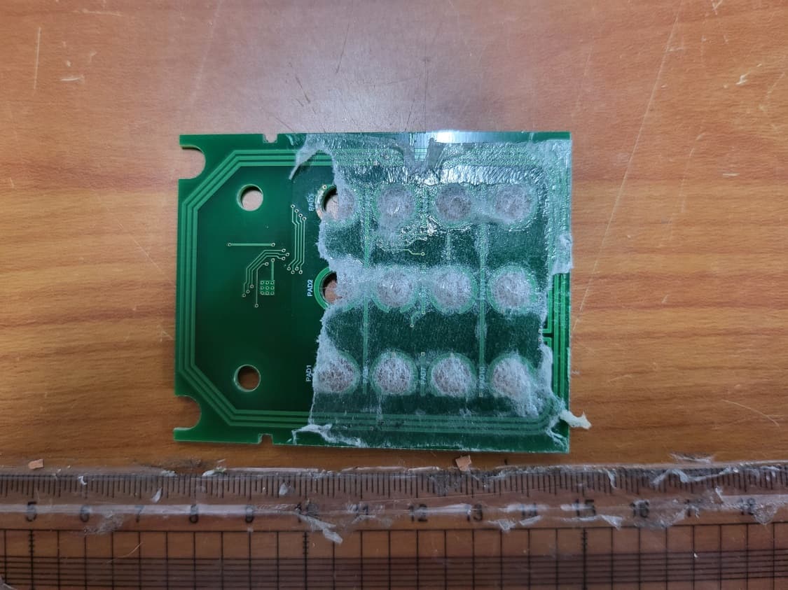
W6YHP400
Jun 19, 2022HOTEL DOOR LOCK
Equipment Class
DTS - Digital Transmission System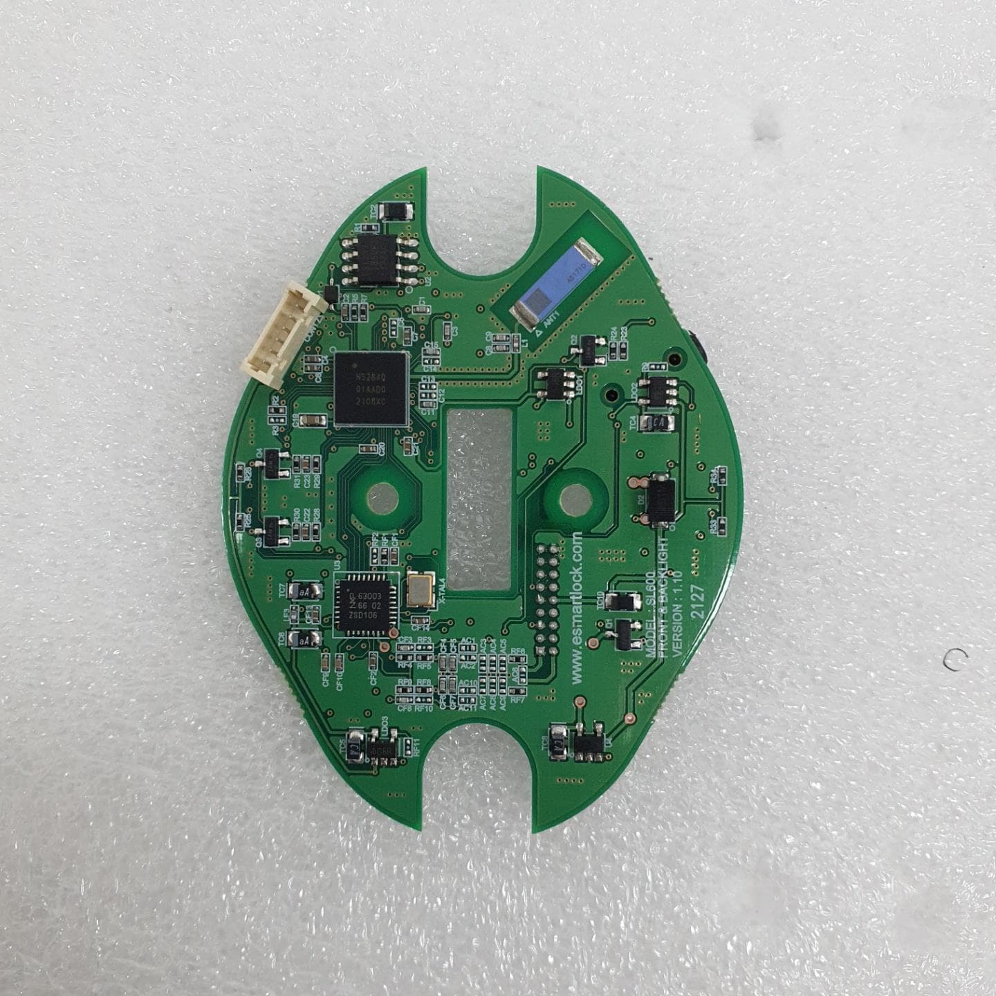
W6YSL600
Aug 26, 2021SLIM LOCK
Equipment Class
DXX - Part 15 Low Power Communication Device Transmitter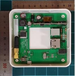
W6YAP300
May 25, 2021ACCESS POINT
Equipment Class
DTS - Digital Transmission System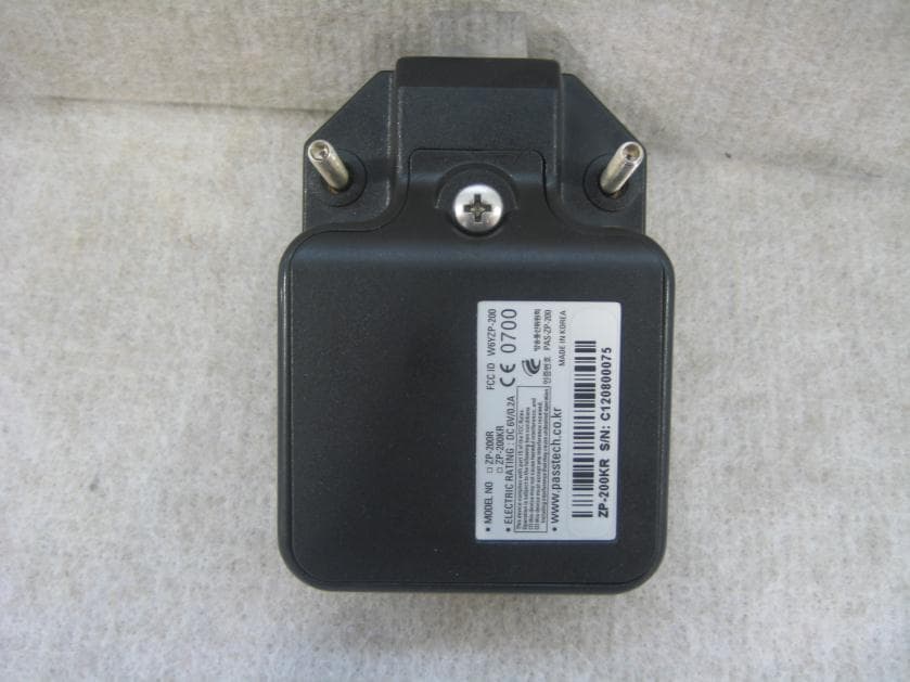
W6YZP-200W
Nov 26, 2012Esmart Touch Lock
Equipment Class
DTS - Digital Transmission System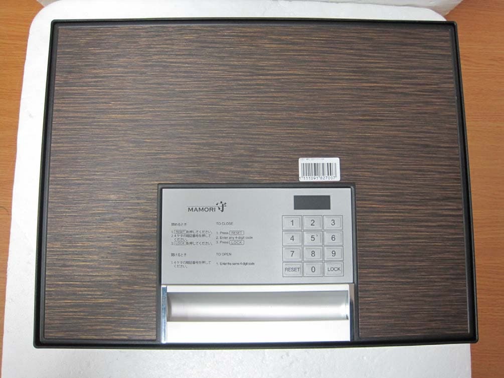
W6YSB-100
Dec 03, 2011Safebox
Equipment Class
DXX - Part 15 Low Power Communication Device Transmitter