W75-BTM0Bluetooth Module
ATTOWAVE CO., LTD
Click to zoom
Application Details
- Equipment Class
- DTS - Digital Transmission System
- Date of Grant
- Nov 15, 2020
- Application Purpose
- Original Equipment
- Date of Application
- Nov 15, 2020
- Equipment Note
- Bluetooth Module
- Frequency Range
- 2402.00000000 - 2480.00000000
- Company
- ATTOWAVE CO., LTD
- Country
- South Korea
Documents & Files
Document Text
Text extracted from the exhibit documents filed with the FCC. Open a document above to read the original.
Users Manual
1 BTM0 Bluetooth Module User Manual ATTOWAVE CO., LTD. 2 Table of Contents 1. Introduction ∙∙∙∙∙∙∙∙∙∙∙∙∙∙∙∙∙∙∙∙∙∙∙∙∙∙∙∙∙∙∙∙∙∙∙∙∙∙∙∙∙∙∙∙∙∙∙∙∙∙∙∙∙∙∙∙∙∙∙∙∙∙∙∙∙∙∙∙∙∙∙∙∙∙∙∙∙∙∙∙∙∙∙∙∙∙∙∙∙∙∙∙∙∙∙∙∙∙∙∙∙∙∙∙∙∙∙∙∙∙∙∙∙∙∙∙∙∙∙∙∙∙∙∙∙∙∙∙∙∙∙∙∙∙∙∙∙ 3 1.1 Product Overview ∙∙∙∙∙∙∙∙∙∙∙∙∙∙∙∙∙∙∙∙∙∙∙∙∙∙∙∙∙∙∙∙∙∙∙∙∙∙∙∙∙∙∙∙∙∙∙∙∙∙∙∙∙∙∙∙∙∙∙∙∙∙∙∙∙∙∙∙∙∙∙∙∙∙∙∙∙∙∙∙∙∙∙∙∙∙∙∙∙∙∙∙∙∙∙∙∙∙∙∙∙∙∙∙∙∙∙∙∙∙∙∙∙∙∙∙∙∙∙∙∙∙∙ 3 1.2 Features ∙∙∙∙∙∙∙∙∙∙∙∙∙∙∙∙∙∙∙∙∙∙∙∙∙∙∙∙∙∙∙∙∙∙∙∙∙∙∙∙∙∙∙∙∙∙∙∙∙∙∙∙∙∙∙∙∙∙∙∙∙∙∙∙∙∙∙∙∙∙∙∙∙∙∙∙∙∙∙∙∙∙∙∙∙∙∙∙∙∙∙∙∙∙∙∙∙∙∙∙∙∙∙∙∙∙∙∙∙∙∙∙∙∙∙∙∙∙∙∙∙∙∙∙∙∙∙∙∙∙∙∙∙∙∙∙∙∙∙ 3 1.2.1 Bluetooth ∙∙∙∙∙∙∙∙∙∙∙∙∙∙∙∙∙∙∙∙∙∙∙∙∙∙∙∙∙∙∙∙∙∙∙∙∙∙∙∙∙∙∙∙∙∙∙∙∙∙∙∙∙∙∙∙∙∙∙∙∙∙∙∙∙∙∙∙∙∙∙∙∙∙∙∙∙∙∙∙∙∙∙∙∙∙∙∙∙∙∙∙∙∙∙∙∙∙∙∙∙∙∙∙∙∙∙∙∙∙∙∙∙∙∙∙∙∙∙∙∙∙∙∙ 3 1.3 Specifications Table ∙∙∙∙∙∙∙∙∙∙∙∙∙∙∙∙∙∙∙∙∙∙∙∙∙∙∙∙∙∙∙∙∙∙∙∙∙∙∙∙∙∙∙∙∙∙∙∙∙∙∙∙∙∙∙∙∙∙∙∙∙∙∙∙∙∙∙∙∙∙∙∙∙∙∙∙∙∙∙∙∙∙∙∙∙∙∙∙∙∙∙∙∙∙∙∙∙∙∙∙∙∙∙∙∙∙∙∙∙∙∙∙∙∙∙∙∙∙∙∙ 4 1.3.1 General ∙∙∙∙∙∙∙∙∙∙∙∙∙∙∙∙∙∙∙∙∙∙∙∙∙∙∙∙∙∙∙∙∙∙∙∙∙∙∙∙∙∙∙∙∙∙∙∙∙∙∙∙∙∙∙∙∙∙∙∙∙∙∙∙∙∙∙∙∙∙∙∙∙∙∙∙∙∙∙∙∙∙∙∙∙∙∙∙∙∙∙∙∙∙∙∙∙∙∙∙∙∙∙∙∙∙∙∙∙∙∙∙∙∙∙∙∙∙∙∙∙∙∙∙∙∙ 4 1.3.2 Bluetooth ∙∙∙∙∙∙∙∙∙∙∙∙∙∙∙∙∙∙∙∙∙∙∙∙∙∙∙∙∙∙∙∙∙∙∙∙∙∙∙∙∙∙∙∙∙∙∙∙∙∙∙∙∙∙∙∙∙∙∙∙∙∙∙∙∙∙∙∙∙∙∙∙∙∙∙∙∙∙∙∙∙∙∙∙∙∙∙∙∙∙∙∙∙∙∙∙∙∙∙∙∙∙∙∙∙∙∙∙∙∙∙∙∙∙∙∙∙∙∙∙∙∙∙ 4 1.3.3 Operating Conditions ∙∙∙∙∙∙∙∙∙∙∙∙∙∙∙∙∙∙∙∙∙∙∙∙∙∙∙∙∙∙∙∙∙∙∙∙∙∙∙∙∙∙∙∙∙∙∙∙∙∙∙∙∙∙∙∙∙∙∙∙∙∙∙∙∙∙∙∙∙∙∙∙∙∙∙∙∙∙∙∙∙∙∙∙∙∙∙∙∙∙∙∙∙∙∙∙∙∙∙∙∙∙∙∙ 4 2. Pin Definition ∙∙∙∙∙∙∙∙∙∙∙∙∙∙∙∙∙∙∙∙∙∙∙∙∙∙∙∙∙∙∙∙∙∙∙∙∙∙∙∙∙∙∙∙∙∙∙∙∙∙∙∙∙∙∙∙∙∙∙∙∙∙∙∙∙∙∙∙∙∙∙∙∙∙∙∙∙∙∙∙∙∙∙∙∙∙∙∙∙∙∙∙∙∙∙∙∙∙∙∙∙∙∙∙∙∙∙∙∙∙∙∙∙∙∙∙∙∙∙∙∙∙∙∙∙∙∙∙∙∙∙∙∙∙∙ 5 3. Electrical Characteristics ∙∙∙∙∙∙∙∙∙∙∙∙∙∙∙∙∙∙∙∙∙∙∙∙∙∙∙∙∙∙∙∙∙∙∙∙∙∙∙∙∙∙∙∙∙∙∙∙∙∙∙∙∙∙∙∙∙∙∙∙∙∙∙∙∙∙∙∙∙∙∙∙∙∙∙∙∙∙∙∙∙∙∙∙∙∙∙∙∙∙∙∙∙∙∙∙∙∙∙∙∙∙∙∙∙∙∙∙∙∙∙∙∙∙∙ 6 3.1 Absolute Maximum Ratings ∙∙∙∙∙∙∙∙∙∙∙∙∙∙∙∙∙∙∙∙∙∙∙∙∙∙∙∙∙∙∙∙∙∙∙∙∙∙∙∙∙∙∙∙∙∙∙∙∙∙∙∙∙∙∙∙∙∙∙∙∙∙∙∙∙∙∙∙∙∙∙∙∙∙∙∙∙∙∙∙∙∙∙∙∙∙∙∙∙∙∙∙∙∙∙∙∙∙∙∙∙∙∙∙∙∙∙ 6 3.2 Recommended Operating Conditions ∙∙∙∙∙∙∙∙∙∙∙∙∙∙∙∙∙∙∙∙∙∙∙∙∙∙∙∙∙∙∙∙∙∙∙∙∙∙∙∙∙∙∙∙∙∙∙∙∙∙∙∙∙∙∙∙∙∙∙∙∙∙∙∙∙∙∙∙∙∙∙∙∙∙∙∙∙∙∙∙∙∙∙∙∙∙∙∙∙∙∙∙∙ 6 3.3 Digital IO Pin DC Characteristics ∙∙∙∙∙∙∙∙∙∙∙∙∙∙∙∙∙∙∙∙∙∙∙∙∙∙∙∙∙∙∙∙∙∙∙∙∙∙∙∙∙∙∙∙∙∙∙∙∙∙∙∙∙∙∙∙∙∙∙∙∙∙∙∙∙∙∙∙∙∙∙∙∙∙∙∙∙∙∙∙∙∙∙∙∙∙∙∙∙∙∙∙∙∙∙∙∙∙∙ 6 4. Federal Communications Commission Interference Statement∙∙∙∙∙∙∙∙∙∙∙∙∙∙∙∙∙∙∙∙∙∙∙∙∙∙∙∙∙∙∙∙∙∙∙∙∙∙∙∙∙∙∙∙∙∙∙∙∙∙∙∙∙∙∙∙∙∙∙∙∙ 7 3 1. Introduction 1.1 Product Overview The BTM0 was an Attowave co., Ltd. Bluetooth Module. The BTM0 is used to add Bluetooth to Radar detectors. It uses Bluetooth Low Energy to communicate between the Radar detector and a Bluetooth LE equipped smartphone. 1.2 Features 1.2.1 Bluetooth · DA14585(Bluetooth Low Energy 4.2) · Processor · ARM Cortex-M0, 32bit, 16MHz · Dedicated Link Layer Processor · AES-128bit encryption Processor · Memory · 64 KB OTP Memory · 128 KB ROM · 96 KB Retention SRAM · External Flash · 8M-Byte SPI Flash · Operating Clock · 16MHz · Antenna · Embedded Antenna · IO Interfaces · UART · SWD · GPIO · Power Input · Single 3.3V Power Input · Package · Module – 25 x 15 x 1 mm (L x W x H) 4 1.3 Specifications Table 1.3.1 General Feature Description Product Description Bluetooth Module Major Chipset Dialog DA14585 Host Interface UART Dimension 25 x 15 x 1 mm (L x W x H) Antenna Micro-strip Antenna (Built-in) 1.3.2 Bluetooth Feature Description Bluetooth version BLE 4.2 Frequency Range 2402 ~ 2480 MHz Modulation GFSK for Bluetooth Target power -2dBm 1.3.3 Operating Conditions Feature Description Operating Conditions Voltage 3.3V Operating Temperature -30 ~ 85°C Operating Humidity TBD Storage Temperature -40 ~ 85°C Storage Humidity TBD ESD Protection Human Body Model TBD Changed Device Model TBD Mode Target Power Measured Power [dBm] [dBm] BLE_1Mbps_Lowest -2 -2.38 BLE_1Mbps_Middle -2 -2.07 BLE_1Mbps_Highest -2 -1.8 5 2. Pin Definition Pin name Basic Description Type Level Power Supply VBAT3V 3.3V Power Supply AIO 3.3V VBAT_RF 3.3V Power Supply AIO 3.3V GND Ground AIO Debug Interface and Reset SWDIO JTAG Data input/output I/O 3.3V SWCLK JTAG clock signal input I/O 3.3V RST Reset signal (active high). Must be connected to GND if not used I 3.3V SPI Bus Interface SPI_CLK Input/Output, SPI clock DO 3.3V SPI_EN Output, SPO chip enable DO 3.3V SPI_DO Output, SPI Data output DO 3.3V SPI_DI Input, SPI Data input DI 3.3V UART Interface URX Input, UART receive data DI 3.3V UTX Output, UART transmit data DO 3.3V GPIO P1.3 GPIO I/O 3.3V Clock XTAL16Mm Output, Crystal output for the 16 MHz XTAL AO XTAL16Mp Input, Crystal input for the 16 MHz XTAL AI 6 3. Electrical Characteristics 3.1 Absolute Maximum Ratings Symbol Parameter Min Typ Max Unit VBAT3V 3.3V power supply 3.3 3.6 V 3.2 Recommended Operating Conditions Symbol Parameter Min Typ Max Unit VBAT3V 3.3V power supply 3.0 3.3 3.6 V 3.3 Digital IO Pin DC Characteristics Symbol Parameter Min Typ Max Unit VIH Input High Voltage 0.84 V VIL Input Low Voltage 0.36 V Federal Communications Commission Interference Statement 1.1 Liability for illegal acts Anyone who uses this product for illegal purposes shall be liable and he or she shall be held responsible for all and any consequences. 1.2 FCC licensing information λ Federal Communications Commission Interference statement NOTE: Change or modification not expressly approved by the party responsible for compliance could void the user’s authority to operate the equipment. This equipment has been tested and found to comply with the limits for a Class B digital device, pursuant to Part 15 of the FCC Rules. These limits are designed to provide reasonable protection against harmful int erference in a residential installation. This equipment generates, uses, and can radiate radio frequency energy and, if not installed and used in accordance with the instructions, may cause harmful interference to radio communications. However, there is no guarantee that interference will not occur in a particular installation. If this equipment does cause harmful interference to radio or television reception which can be determined by turning the equipment off and on, the user is encouraged to try to correct the interference by one or more of the following measures. - Reorient or relocate the receiving antenna. - Increase the separation between the equipment and receiver. - …
Text truncated - open the document above for the full version.
Users Manual
ODIN C-497 OWNER’S MANUAL ROCKY MOUNTAIN INTRODUCTION Thank you for purchasing the ODIN C-497 radar/laser developed by Rocky Mountain Radar. ODIN C-497 is the first and unique sophisticated radar and laser detector in the world which has very good performance. We are pleased to have you as a valued customer and hope you will be delighted with your ODIN C-497. This manual provides al l the information you need putting the ODIN C-497 to work for you. NOTE: Always obey all local and federal laws when using this device. FCC ID: QKK-ODN contains FCC ID: W75-BTM0 This equipment should be installed and operated with a minimum distance of 20 centimeters between the radiator and your body or nearby persons. This device complies with part 15 of the FCC Rules. Operation is subject to the following two conditions: (1) This device may not cause harmful interference, and (2) this device must accept any interference received, including interference that may cause undesired operation. In addition, any changes or modifications to this product, which are not expressly approved by Rocky Mountain Radar in writing, could void the user’s authority to operate this product. ODIN C-497 H H H H 二 0 D I N ( \ , ' ) ( ' : ' ' ) ( \ , ' ) ( \ , ' ) MENU DIM MUTE CITY DD□ ============================================================================= FEATURE ============================================================================= 1. X, K, Ka Band, Laser Detection 2. Display : 256x32 Pixel RED OLED 3. 4 Button : [MENU]-[DIM]-[MUTE]-[CITY] 4. Dim Mode : BRIGHT -> DIM -> DIMMER -> DARK 5. Mute On -> AutoMute -> Mute Off 6. City Mode : HIGHWAY <-> CITY 7. Voice On / Off 8. Voice Language : ENGLISH / SPANISH 9. Alarm Tone : HIGH / LOW 10. X Band On/Off 11. K Band On/Off 12. Ka Band On/Off 13. Laser On/Off 14. K Narrow/Wide 15. Ka Narrow/Wide 16. K Band Filter On/Off 17. TSF On/Off 18. Voltage Meter On/Off 19. Scrambler On/Off 20. Self Test On/Off 21. Factory Reset Mode 22. User Setting Memory 23. Factory Test Mode ============================================================================= Display ============================================================================= 1. RED OLED Display with 256x32 Pixel 2. Display on Stand by Mode 2.1. HIGHWAY : “□□□□□HIGHWAY□□□□” 2.2. CITY : “□□□□□□CITY□□□□□□” 3. Display for Laser/Radar Alerts 3.1. Laser "□□□□□LASER□□□□□□" 3.2. X Band "□□□□X□▶□□□□□1□□□ " "□□□□X□▶▶□□□□2□□□ " "□□□□X□▶▶▶□□□ 3□□□ " "□□□□X□▶▶▶▶□□ 4□□□ " "□□□□X□▶▶▶▶▶□5□□□ " 3.3. K Band "□□□□K□▶□□□□□1□□□ " "□□□□K□▶▶□□□□2□□□ " "□□□□K□▶▶▶□□□ 3□□□ " "□□□□K□▶▶▶▶□□ 4□□□ " "□□□□K□▶▶▶▶▶□5□□□ " 3.4. Ka Band "□□□ Ka □▶□□□□□1□□□ " "□□□ Ka □▶▶□□□□2□□□ " "□□□ Ka □▶▶▶□□□ 3□□□ " "□□□ Ka □▶▶▶▶□□ 4□□□ " "□□□ Ka □▶▶▶▶▶□5□□□ " 3.5. RD ( K, Ka Band ) Alarm Levels : 1-5 4. Dim Mode 4.1. BRIGHT: OLED Display brightens. 4.2. DIM : OLED Display dims. 4.3. DIMMER : OLED Display gets dimmer. 4.4. DARK : OLED Display turns off, only a small dot is moving from left to right regardless of alarms.. ============================================================================= Preamble ============================================================================= 1.If Selft test mode is on , Self test will start in the order of the followng after the start message «Rocky Mountain Radar» 1) Scrambler Test ( Only if Scrambler mode is on ) 2) X Alarm (Signal Strenghth level 1-5) 3) K Alarm (Signal Strenghth level 1-5) 4) Ka Alarm (Signal Strength level 1-5) 5) Laser Alarm User settings on Voice on/off, language, Alarm Sound Tone, Scrambler ON/Off will be applied as they are. 1.1. Display and Audio Alarms on Self Test Mode 1) “ □SCRAMBLER□TEST□" ( Display & Scrambler Test Sound – only when Scrambler Mode is On) 2) " □□□□X□▶□□□□□1□□□ " ~ " □□□□K□▶▶▶▶▶□5□□□ " ( K Display & Sound Alarm ) 3) " □□□□K□▶□□□□□1□□□ " ~ " □□□□K□▶▶▶▶▶□5□□□ " ( K Display & Sound Alarm ) 4) " □□□ Ka □▶□□□□□1□□□ " ~ " □□□ Ka □▶▶▶▶▶□5□□□ " ( Ka Display & Sound Alarm ) 5) " □□□□□LASER□□□□□□" ( Laser Display & Sound Alarm ) 2. After Self test, display will show status of user settings in the order of the following. 1) Voice On/Off (only display, No beep) 2) English/Spanish (only display, No beep) 3) Tone High/Low (only display, No beep) 4) X Band On/Off (only display, No beep) 5) K Band On/Off (only display, No beep) 6) Ka Band On/Off (only display, No beep) 7) Laser On/Off (only display, No beep) 8) K Narrow/Wide (only display, No beep) 9) Ka Narrow/Wide (only display, No beep) 10) K Band Filter On/Off (only display, No beep) 11) TSF On/Off (only display, No beep) 12) Voltage Meter On/Off (only display, No beep) 13) Scrambler On/Off (only display, No beep) 14) Self Test On/Off (only display, No beep) 15) Dim Mode (only display, No beep) 16) Mute Mode (only display, No beep) 2.1. Display will show the following according to the settings. 1) Voice On/Off : "□□□□VOICE□ON□□□□” / "□□□□VOICE□OFF□□□” 2) English/Spanish : “□□□□ENGLISH□□□□□” / “□□□□SPANISH□□□□□” 3) Tone High/Low : "□□□□TONE□HIGH□□□” / "□□□□TONE□LOW□□□□” 4) X Band On/Off : "□□□X□Band□On□□□□” / "□□□X□Band□Off□□□” 5) K Band On/Off : "□□□K□Band□On□□□□” / "□□□K□Band□Off□□□” 6) Ka Band On/Off : "□□Ka□Band□On□□□□” / "□□Ka□Band□Off□□□” 7) Laser On/Off : "□□□□Laser□On□□□□” / "□□□□Laser□Off□□□” 8) K Narrow/Wide : "□□□□K□Narrow□□□□” / "□□□□□K□Wide□□□□□” 9) Ka Narrow/Wide : "□□□Ka□Narrow□□□□” / "□□□□Ka□Wide□□□□□” 10) K Band Filter On/Off : "□□K□FILTER□ON□□□” / "□□K□FILTER□OFF□□” 11) TSF On/Off : "□□□□□TSF□On□□□□□” / "□□□□□TSF□Off□□□□ 12) Voltage Meter On/Off : "VoltageMeter□On□” / "VoltageMeter□Off” 13) Scrambler On/Off : "□□SCRAMBLER□ON□□” / "□□SCRAMBLER□OFF□” 14) Self Test On/Off : “□□SELF□TEST□ON□□” / “□□SELF□TEST□OFF□” 15) Dim Mode : “□□□□□BRIGHT□□□□□” / “□□□□□□DIM□□□□□□□”/ “□□□□□DIMMER□□□□□”/ “□□□□□□DARK□□□□□□”/ 16) Mute Mode : “□□□□MUTE□ON□□□□□” / “□□□□MUTE□OFF□□□□”/ “□□□□AUTOMUTE□□□□”/ ============================================================================= BUTTON OPERATION ====================================================…
Text truncated - open the document above for the full version.
Cover Letter(s)
Applicant/Grantee Attowave co., Ltd./W75 FCC ID: W75-BTM0 Section 15.212 Modular Transmitters Request for Modular Approval Request for Limited Modular Approval Requirements EUT Conditions Comply (Y/N) Single Modular Approval Requirements 1 The radio elements of the modular transmitter must have their own shielding. The physical crystal and tuning capacitors may be located external to the shielded radio elements. Bluetooth 4.2 LE N* 2 The modular transmitter must have buffered modulation/data inputs (if such inputs are provided) to ensure that the module will comply with Part 15 requirements under conditions of excessive data rates or over-modulation. Y 3 The modular transmitter must have its own power supply regulation. N** 4 The modular transmitter must comply with the antenna and transmission system requirements of Sections 15.203, 15.204(b) and 15.204(c). The antenna must either be permanently attached or employ a “unique” antenna coupler (at all connections between the module and the antenna, including the cable). The “professional installation” provision of Section 15.203 is not applicable to modules but can apply to limited modular approvals under paragraph (b) of this section. Y 5 The modular transmitter must be tested in a stand-alone configuration, i.e., the module must not be inside another device during testing for compliance with Part 15 requirements. Unless the transmitter module will be battery powered, it must comply with the AC line conducted requirements found in Section 15.207. AC or DC power lines and data input/output lines connected to the module must not contain ferrites, unless they will be marketed with the module (see Section 15.27(a)). The length of these lines shall be the length typical of actual use or, if that length is unknown, at least 10 centimeters to insure that there is no coupling between the case of the module and supporting The module is tested inside of a host device, RADAR DETECTOR. N equipment. Any accessories, peripherals, or support equipment connected to the module during testing shall be unmodified and commercially available (see Section 15.31(i)). 6 The modular transmitter must be equipped with either a permanently affixed label or must be capable of electronically displaying its FCC identification number. (A) If using a permanently affixed label, the modular transmitter must be labeled with its own FCC identification number, and, if the FCC identification number is not visible when the module is installed inside another device, then the outside of the device into which the module is installed must also display a label referring to the enclosed module. This exterior label can use wording such as the following: “Contains Transmitter Module FCC ID: XYZMODEL1” or “Contains FCC ID: XYZMODEL1.” Any similar wording that expresses the same meaning may be used. The Grantee may either provide such a label, an example of which must be included in the application for equipment authorization, or, must provide adequate instructions along with the module which explain this requirement. In the latter case, a copy of these instructions must be included in the application for equipment authorization. (B) If the modular transmitter uses an electronic display of the FCC identification number, the information must be readily accessible and visible on the modular transmitter or on the device in which it is installed. If the module is installed inside another device, then the outside of the device into which the module is installed must display a label referring to the enclosed module. This exterior label can use wording such as the following: “Contains FCC certified transmitter module(s).” Any similar wording that expresses the same meaning may be used. The user manual must include instructions on how to access the electronic display. A copy of these instructions must be included in the application for equipment authorization. Y 7 The modular transmitter must comply with any specific rules or operating requirements that ordinarily apply to a complete transmitter and the manufacturer must provide adequate instructions along with the module to explain any such requirements. A copy of these instructions must be included in the application for equipment authorization. Y 8 The modular transmitter must comply with any applicable RF exposure requirements in its final configuration. Y A limited modular approval may be granted for single or split modular transmitters that do not comply with all of the above requirements, e.g., shielding, minimum signaling amplitude, buffered modulation/data inputs, or power supply regulation, if the manufacturer can demonstrate by alternative means in the application for equipment authorization that the modular transmitter meets all the applicable Part 15 requirements under the operating conditions in which the transmitter will be used. Limited modular approval also may be granted in those instances where compliance with RF exposure rules is demonstrated only for particular product configurations. The applicant for certification must state how control of the end product into which the module will be installed will be maintained such that full compliance of the end product is always ensured. - P lease provide a detailed explanation if the answer is “NO” *This module does not have a shield. **Power is supplied from an outside product.
External Photos
http://www.kctl.co.kr This test report shall not be reproduced, except in full, without the written approval External photos of EUT http://www.kctl.co.kr This test report shall not be reproduced, except in full, without the written approval http://www.kctl.co.kr This test report shall not be reproduced, except in full, without the written approval
External Photos
http://www.kctl.co.kr This test report shall not be reproduced, except in full, without the written approval External photos of EUT http://www.kctl.co.kr This test report shall not be reproduced, except in full, without the written approval http://www.kctl.co.kr This test report shall not be reproduced, except in full, without the written approval
ID Label/Location Info
Label location Rear center of the product
Internal Photos
http://www.kctl.co.kr This test report shall not be reproduced, except in full, without the written approval Internal photos of EUT Bluetooth Low Energy Antenna
Internal Photos
http://www.kctl.co.kr This test report shall not be reproduced, except in full, without the written approval Internal photos of EUT BLE Module http://www.kctl.co.kr This test report shall not be reproduced, except in full, without the written approval
RF Exposure Info
verify No.471729462277 KCTL Inc. 65, Sinwon-ro, Yeongtong-gu, Suwon-si, Gyeonggi-do, 16677, Korea TEL: 82-31-285-0894 FAX: 82-505-299-8311 www.kctl.co.kr Report No.: KR20-SRF0280-A Page (2) of (7) KCTL-TIR001-003/3 KP20-05059 Report revision history Date Revision Page No 2020-11-09 Originally issued - 2020-11-12 Updated host device information 4 This report shall not be reproduced except in full, without the written approval of KCTL Inc. This document may be altered or revised by KCTL Inc. personnel only, and shall be noted in the revision section of the document. Any alteration of this document not carried out by KCTL Inc. will constitute fraud and shall nullify the document. This test report is a general report that does not use the KOLAS accreditation mark and is not related to KS Q ISO/IEC 17025 and KOLAS accreditation. General remarks for test reports Nothing significant to report. KCTL Inc. 65, Sinwon-ro, Yeongtong-gu, Suwon-si, Gyeonggi-do, 16677, Korea TEL: 82-31-285-0894 FAX: 82-505-299-8311 www.kctl.co.kr Report No.: KR20-SRF0280-A Page (3) of (7) This test report shall not be reproduced, except in full, without the written approval KCTL-TIR001-003/2 CONTENTS 1. General information ......................................................................................................4 2. Device information ........................................................................................................4 2.1. Host device information ..........................................................................................4 2.2. Frequency/channel operations................................................................................5 3. Measurement uncertainty .............................................................................................5 4. RF Exposure .................................................................................................................6 4.1. Test results..............................................................................................................7 KCTL Inc. 65, Sinwon-ro, Yeongtong-gu, Suwon-si, Gyeonggi-do, 16677, Korea TEL: 82-31-285-0894 FAX: 82-505-299-8311 www.kctl.co.kr Report No.: KR20-SRF0280-A Page (4) of (7) This test report shall not be reproduced, except in full, without the written approval KCTL-TIR001-003/2 1. General information Client : AT TOWAVE Co., Lt d. Address : 1005, 10F Leader's Tower, 60-15 Gasan-dong, Gumchun-gu, Seoul, 153-801 Korea Manufacturer : AT TOWAVE Co., Lt d. Address : 1005, 10F Leader's Tower, 60-15 Gasan-dong, Gumchun-gu, Seoul, 153-801 Korea Laboratory : KCTL Inc. Address : 65, Sinwon-ro, Yeongtong-gu, Suwon-si, Gyeonggi-do, 16677, Korea Accreditations : FCC Site Designation No: KR0040, FCC Site Registration No: 687132 VCCI Registration No. : R-20080, G-20078, C-20059, T-20056 Industry Canada Registration No. : 8035A KOLAS No.: KT231 2. Device information Equipment under test : Bluetooth Module Model : BTM0 Frequency range : 2 402 ㎒ ~ 2 480 ㎒ (Bluetooth (BLE)) Modulation technique : Bluetooth(BLE)_GFSK Number of channels : Bluetooth(BLE)_40ch Power source : DC 3.3 V Antenna specification : Micro-strip Antenna Antenna gain : -0.106 ㏈i Software version : V1.00 Hardware version : B Test device serial No. : N/A Operation temperature : -30 °C ~ 85 °C 2. 1. Host device information Product Name Model Name FCC ID RADAR DETECTOR ODIN C-497 QKK-ODN Note: The EUT is authorized for use in specific End-product. KCTL Inc. 65, Sinwon-ro, Yeongtong-gu, Suwon-si, Gyeonggi-do, 16677, Korea TEL: 82-31-285-0894 FAX: 82-505-299-8311 www.kctl.co.kr Report No.: KR20-SRF0280-A Page (5) of (7) This test report shall not be reproduced, except in full, without the written approval KCTL-TIR001-003/2 2. 2. Frequency/channel operations This device contains the following capabilities: Bluetooth Low Energy Ch. Frequency (㎒) 00 2 402 . . . . 19 2 442 . . . . 39 2 480 Table 2.2.1. Bluetooth Low Energy 3. Measurement uncertainty The measurement uncertainties shown below were calculated in accordance with the requirements of ANSI C63.10-2013. All measurement uncertainty values are shown with a coverage factor of k=2 to indicated a 95 % level of confidence. The measurement data shown herein meets of exceeds the U CISPR measurement uncertainty values specified in CISPR 16-4-2 and thus, can be compared directly to specified limits to determine compliance. Parameter Expanded uncertainty (±) Conducted RF power 1.23 ㏈ KCTL Inc. 65, Sinwon-ro, Yeongtong-gu, Suwon-si, Gyeonggi-do, 16677, Korea TEL: 82-31-285-0894 FAX: 82-505-299-8311 www.kctl.co.kr Report No.: KR20-SRF0280-A Page (6) of (7) This test report shall not be reproduced, except in full, without the written approval KCTL-TIR001-003/2 4. RF Exposure FCC Regulation This document is prepared to show compliance with the RF Exposure requirements as required in §1.1310 of the FCC rules and Regulations. The limit for Maximum Permissible Exposure (MPE), specified in FCC §1.1310, is listed in Table 1-1. According to FCC §1.1310: the criteria listed in the following table shall be used to evaluate the environmental impact of human exposure to radio-frequency (RF) radiation as specified in §1.1307(b). Table 1 – Limits for Maximum Permissible Exposure (MPE) Frequency Range (㎒) Electric Field Strength [V/m] Magnetic Field Strength [A/m] Power Density [㎽/㎠] Averaging Time [minute] (A) Limits for Occupational / Controlled Exposure 0.3 ~ 3.0 614 1.63 *100 6 3.0 ~ 30 1842/f 4.89/f *900/f 2 6 30 ~ 300 61.4 0.163 1.0 6 300 ~ 1 500 / / f/300 6 1 500 ~ 15 000 / / 5 6 (B) Limits for General Population / Uncontrolled Exposure 0.3 ~ 1.34 614 1.63 *100 30 1.34 ~ 30 824/f 2.19/f *180/f 2 30 30 ~ 300 27.5 0.073 0.2 30 300 ~ 1 500 / / f/1 500 30 1 500 ~ 15 000 / / 1.0 30 f=frequency in ㎒, *= plane-wave equivalent power density Per the guidance of KDB 680106, the E-field and H-field limits shown in the table above are extended down to 100 ㎑ KCTL Inc. 65, Sinwon-ro, Yeongtong-gu, Suwon-…
Text truncated - open the document above for the full version.
Test Report
verify No.736718418259 KCTL Inc. 65, Sinwon-ro, Yeongtong-gu, Suwon-si, Gyeonggi-do, 16677, Korea TEL: 82-31-285-0894 FAX: 82-505-299-8311 www.kctl.co.kr Report No.: KR20-SRF0281-B Page (2) of (33) KCTL-TIR001-003/3 KP20-05059 REPORT REVISION HISTORY Date Revision Page No 2020-11-09 Originally issued - 2020-11-11 Updated 7, 33 2020-11-12 Updated host device information 4 This report shall not be reproduced except in full, without the written approval of KCTL Inc. This document may be altered or revised by KCTL Inc. personnel only, and shall be noted in the revision section of the document. Any alteration of this document not carried out by KCTL Inc. will constitute fraud and shall nullify the document. This test report is a general report that does not use the KOLAS accreditation mark and is not related to KS Q ISO/IEC 17025 and KOLAS accreditation. General remarks for test reports Nothing significant to report. KCTL Inc. 65, Sinwon-ro, Yeongtong-gu, Suwon-si, Gyeonggi-do, 16677, Korea TEL: 82-31-285-0894 FAX: 82-505-299-8311 www.kctl.co.kr Report No.: KR20-SRF0281-B Page (3) of (33) This test report shall not be reproduced, except in full, without the written approval KCTL-TIR001-003/3 KP20-05059 CONTENTS 1. General information ......................................................................................................4 2. Device information ........................................................................................................4 2.1. Host device information ..........................................................................................4 2.2. Frequency/channel operations................................................................................5 2.3. Duty Cycle ..............................................................................................................5 3. Antenna requirement ....................................................................................................6 4. Summary of tests ..........................................................................................................7 5. Measurement uncertainty .............................................................................................8 6. Measurement results explanation example ..................................................................9 7. Test results ................................................................................................................. 10 7.1. Maximum peak output power ................................................................................ 10 7.2. Peak Power Spectral Density ............................................................................... 13 7.3. 6 dB Bandwidth(DTS Channel Bandwidth) ........................................................... 15 7.4. Spurious Emission, Band Edge and Restricted bands .......................................... 17 7.5. Conducted Spurious Emission .............................................................................. 29 7.6 AC Conducted emission .......................................................................................... 31 8. Measurement equipment ............................................................................................ 33 KCTL Inc. 65, Sinwon-ro, Yeongtong-gu, Suwon-si, Gyeonggi-do, 16677, Korea TEL: 82-31-285-0894 FAX: 82-505-299-8311 www.kctl.co.kr Report No.: KR20-SRF0281-B Page (4) of (33) This test report shall not be reproduced, except in full, without the written approval KCTL-TIR001-003/3 KP20-05059 1. General information Client : AT TOWAVE Co., Lt d. Address : 1005, 10F Leader's Tower, 60-15 Gasan-dong, Gumchun-gu, Seoul, 153-801 Korea Manufacturer : AT TOWAVE Co., Lt d. Address : 1005, 10F Leader's Tower, 60-15 Gasan-dong, Gumchun-gu, Seoul, 153-801 Korea Laboratory : KCTL Inc. Address : 65, Sinwon-ro, Yeongtong-gu, Suwon-si, Gyeonggi-do, 16677, Korea Accreditations : FCC Site Designation No: KR0040, FCC Site Registration No: 687132 VCCI Registration No. : R-20080, G-20078, C-20059, T-20056 Industry Canada Registration No. : 8035A KOLAS No.: KT231 2. Device information Equipment under test : Bluetooth Module Model : BTM0 Frequency range : 2 402 ㎒ ~ 2 480 ㎒ (Bluetooth (BLE)) Modulation technique : Bluetooth(BLE)_GFSK Number of channels : Bluetooth(BLE)_40ch Power source : DC 3.3 V Antenna specification : Micro-strip Antenna Antenna gain : -0.106 ㏈i Software version : V1.00 Hardware version : B Test device serial No. : N/A Operation temperature : -30 °C ~ 85 °C 2. 1. Host device information Product Name Model Name FCC ID RADAR DETECTOR ODIN C-497 QKK-ODN Note: The EUT is authorized for use in specific End-product. KCTL Inc. 65, Sinwon-ro, Yeongtong-gu, Suwon-si, Gyeonggi-do, 16677, Korea TEL: 82-31-285-0894 FAX: 82-505-299-8311 www.kctl.co.kr Report No.: KR20-SRF0281-B Page (5) of (33) This test report shall not be reproduced, except in full, without the written approval KCTL-TIR001-003/3 KP20-05059 2. 2. Frequency/channel operations This device contains the following capabilities: Bluetooth Low Energy Ch. Frequency (㎒) 00 2 402 . . . . 20 2 442 . . . . 39 2 480 Table 2.2.1. Bluetooth Low Energy 2. 3. Duty Cycle Test mode Period (ms) On time (ms) Duty cycle Duty Cycle Factor (dB) (Linear) (%) 1M Bits/s, 37 Packet 0.626 0.391 0.624 9 62.50 2.04 Notes. 1. Duty cycle (Linear) = Ton time / Period 2. DCF(Duty cycle factor) = 10log(1/duty cycle) 1M Bits/s, 37 Packet Blank KCTL Inc. 65, …
Text truncated - open the document above for the full version.
Contact Information
Applicant
Jeong Han Kim
Test Firm
Eurofins KCTL Co., Ltd.Sung-su Lim
Technical Specifications
| # | Rule Parts | Frequency Range | Power Output |
|---|---|---|---|
| 1 | 15C | 2.40 GHz - 2.48 GHz | 800.00 µW |
Other Applications from ATTOWAVE CO., LTD

W75-D-Y10
Apr 13, 2020RADAR DETECTOR
Equipment Class
CRD - Part 15 Radar Detector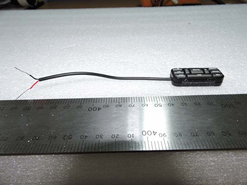
W75-RL-RCUIII
Aug 17, 2015Remote Control Unit
Equipment Class
DSC - Part 15 Security/Remote Control Transmitter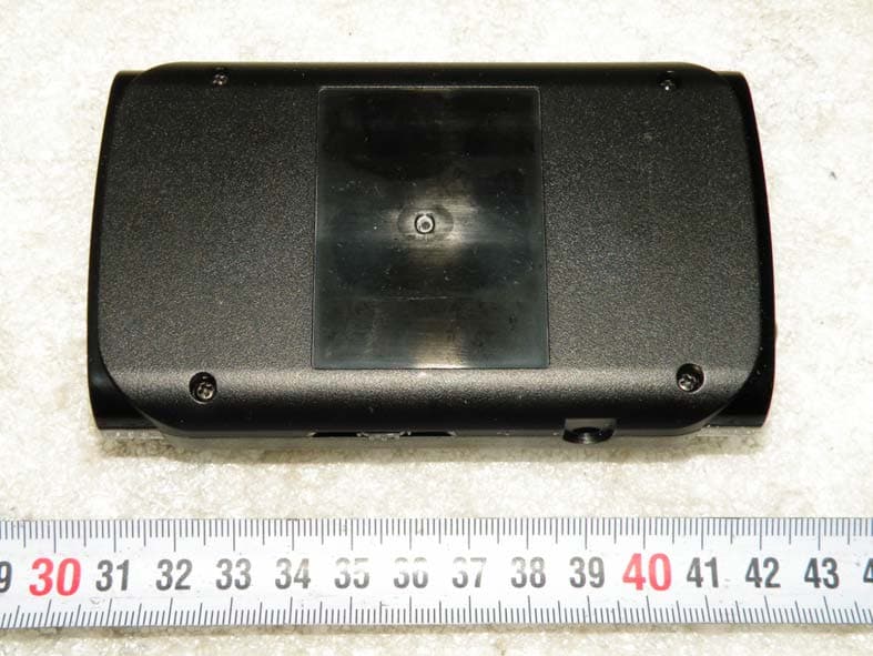
W75-RD950
Nov 06, 2014RADAR DETECTOR
Equipment Class
CRD - Part 15 Radar Detector
W75-RLS2
Nov 06, 2014RADAR DETECTOR
Equipment Class
CRD - Part 15 Radar Detector
W75-CCT278
Feb 24, 2014RADAR DETECTOR
Equipment Class
CRD - Part 15 Radar Detector