W75-M1K-Y12RADAR DETECTOR
ATTOWAVE CO., LTD
Click to zoom
Application Details
- Equipment Class
- CRD - Part 15 Radar Detector
- Date of Grant
- Apr 04, 2010
- Application Purpose
- Original Equipment
- Date of Application
- Apr 04, 2010
- Equipment Note
- RADAR DETECTOR
- Frequency Range
- 33400.00000000 - 36000.00000000
- Company
- ATTOWAVE CO., LTD
- Country
- South Korea
Documents & Files
Document Text
Text extracted from the exhibit documents filed with the FCC. Open a document above to read the original.
Users Manual
RL100 OWNERS MANUAL Register your K40 RL100 today to activate your guarantees: Guaranteed immunity from speeding tickets If you get a speeding ticket within one year of purchase, we’ll reimburse you for the full cost of the ticket.* Guaranteed performance If your K40 radar detection system does not outperform any other radar detector you’ve owned, return it within 30 days for a full product credit. One year warranty K40 offers a one-year “repair or replace” warranty if your product fails to work properly. *Offer not valid for speeding ticket violations incurred in school or construction zones, or connected with a DUI. Register your RL100 online today by visiting K40.com/register Mounting and Powering the RL100 Mounting Instructions To help ensure that your RL100 functions properly and offers maximum protection, please follow these mounting instructions: 1.Cleanthe area of the windshield where the unit will be mounted.* 2.Attachthe supplied Windshield Mounting Bracketto your car’s windshield by firmly pressing the suction cups in the bracket to the windshield. a. Mount the bracket as low as possible near the center of the windshield. b. Do not mount the unit behind wipers or any metal obstructions. 3.Slidethe RL100 unit itself on to the bracket to complete the mounting. 4.Levelthe radar detector, if necessary, by carefully bending the Windshield Mounting Bracket. *IMPORTANT NOTE:Some windshields include a metallic coating that can significantly affect reception of radar signals. Consult with your dealer or check your vehicle’s owner ‘s manual to determine if your windshield has such a coating. Power Connection 1. Plug the small end of the supplied Power Cordinto the Power Input Jackon the side of the radar detector. 2. Plug the large end of the Power Cordinto your vehicle’s cigarette lighter socket or other 12V outlet. 3. Switch on the RL100 by turning the Power On/Volume Control Wheellocated on left side of the unit. No power?See Troubleshooting Guide on page xx. 4 Quick Start (using factory default settings) Once your K40 RL100 has been mounted and had the power connected, you may begin using immediately by following these steps: 1.Switch on the RL100–Turn the Power On/Volume Control Wheelon the side of the unit. 2.Wait for Test Scan to complete– The radar detector will announce(voice) and display(screen) K40 SCANthen go through a “wake up sequence” lasting approximately 5 seconds . a. You will hear and see all bands tested. Adjust the volume during this test. b. Upon completion of the sequence scan, the screen will display HIGHWAY. 3.Wait for GPS Connection– After searching for available satellites, the unit will announce “GPS Connected” then displayGPS . 4.You’re ready to drive!– The RL100 will now display your speed and direction of travel. For example, if you are driving west at 57 mph the display will show _W 57_. Please read the entire Owner’s Manual to fully understand all of the RL100’s operations and functions. 5 Receiving Alerts The K40 RL100 provides a combination of audio and visual alerts to warn you when radar and laser signals are detected. Radar Alert Sequence The RL100 detects X, K and KA-Band radar signals. When a signal is identified: •A voice alerts which band was detected. (This assumes the factory default “Voice ON” setting has not been changed.) •A series of beeps indicates the strength of the signal. Each band has its own distinctive beep. (Volume reduces automatically after 5 seconds.) •The display will provide you band and strength information. Radar Alert Examples: You are driving 45 mph and a low K-Band is detected. Visual Alert: K 2 45 Audio Alert:Voice announces “K-Band” followed by slow beeps. As you approach the source, you slow to 40 mph and the signal becomes stronger: Visual Alert:K 8 40 Audio Alert: Beeping is faster due to stronger signal. Radar source strength:lowmediumstrong Display reading:123 456 789 Audio alert beeps:slowerfaster 6 Laser Alert Sequence When the RL100 detects a laser signal: •A voice alerts announces “Laser.” (This assumes the factory default “Voice ON” setting has not been changed.) •You then hear a distinctive audio tone. (Volume reduces automatically after 5 seconds.) •Display indicates laser has been detected and reports your speed. •NOTE:Unlike radar, signal strength from laser remains constant. Laser Alert Example: You are driving 55 mph and laser is detected. Visual Alert: LASER 55 Audio Alert: Voice announces “Laser” followed by unique tone. Alerts from non-police signals Your RL100 is sensitive enough to detect signals generated by non-police equipment, such as bank security systems. To learn how to deal with these signals, please read about FILTER options (page xx) and the MARK Location function (page xx). 7 Special Features/Functions Mute Sounds Using the MUTEbutton, the RL100 provides you two ways to mute audio alerts (both voice and tones) for either 15 seconds or 2 minutes: •OPTION 1: Silence all audio after an alert has sounded. •OPTION 2: Silence all audio for a preset time before any alert occurs. (Example:You may mute sounds for 2 minutes prior to making a phone call.) For either option, here’s how to mute your device: After pressing the MUTE button, the display will show Mute On_and the voice will announce “Mute On.” NOTE:While this feature is engaged you will only receive new alerts as visual indications on the display. Mark Location The “Mark” function conveniently allows you to store specific locations and provide you two levels of alert: Level 1, MUTE— Mute a future alert from a location known to contain non-police signals, such as a bank that’s known to transmit security signals that trigger your detector. Mute audio forPress and release 15 secondsortheMUTE button duration of the alert Mute audio forPress and hold MUTE 2 minutesorthebuttonfor3 seconds duration of the alert 8 •To activate, press and release MARK buttonwhen you are at the location. •Display shows Mute Locand voice announces “Location Muted”.…
Text truncated - open the document above for the full version.
Cover Letter(s)
SCS-F18: Project and Product Certification Representative Authorization Letter Page 1 of 2 Rev 2.0 2206 Ringwood Avenue San Jose, CA 95131 Tel: 408-526-1188 Fax: 408-526-1088 Email: [email protected] Project and Product Certification Representative Authorization Letter Revision History Reason for Amendment (current / obsolete) From To Approved Date Initial Release (current) 1.0 1.0 Nov-14-2006 Revised wording (current) 1.0 2.0 Sept–25-2007 SCS-F18: Project and Product Certification Representative Authorization Letter Page 2 of 2 Rev 2.0 April 02, 2010 To: SIEMIC, INC. 2206 Ringwood Avenue, San Jose, CA 95131 USA Dear Sir/Madam, Re: Project and Product Certification Representative Authorization Letter We, ATTOWAVE CO., LTD. hereby authorize SIEMIC, INC. to act as a Certification Body for certifying for the following project(s): RADAR DETECTOR / RL100 (FCC ID: W75-M1K-Y12) We affirm that between SIEMIC and ATTOWAVE CO., LTD., any difference in understanding, including test plan, measurement methods, applicable standards and relevant procedures and processes have been resolved prior to commencement of testing activities. Sincerely, Hyun Joo, Cho / Director ATTOWAVE CO., LTD. 1005, 10F Leader’s Tower, 60-15 Gasan-dong, Gumchun-gu, Seoul, 153-801 Korea
Cover Letter(s)
SCS-F19: Confidentiality Request Letter Rev 1.0 Nov 14, 2006 Confidentiality Request Letter Revision History Reason for Amendment (current / obsolete) From To Approved Date Initial Release (current) 1.0 1.0 Nov-14-2006 SCS-F19: Confidentiality Request Letter Rev 1.0 Nov 14, 2006 April 02, 2010 To: Federal Communications Commission Authorization and Evaluation Division Confidentiality Request regarding application for certification of FCC ID: W75-M1K-Y12 We hereby request confidential treatment of information accompanying this application as outlined below: - Block Diagram - Circuit Diagram - Operational description The above materials contain trade secrets and proprietary information not customarily released to the public. The public disclosure of these materials may be harmful to the applicant and provide unjustified benefits to its competitors. The applicant understands that pursuant to Section 0.457 & 0.459 of the Rules, disclosure of this application and all accompanying documentation will not be made before the date of the Grant for this application. Sincerely, Hyun Joo, Cho / Director ATTOWAVE CO., LTD. 1005, 10F Leader’s Tower, 60-15 Gasan-dong, Gumchun-gu, Seoul, 153-801 Korea
External Photos
Appendix C. External Photographs Report no. ETLE100324.01, Page C1 of C4 Head Office: # 371-51 Gasan-dong, Geumcheon-gu, Seoul, 153-803, Korea Tel : 82-2-858-0786 Fax : 82-2-858-0788 ETLQP-21-F22-0 FCC ID:W75-M1K-Y12 Front view of EUT Rear view of EUT Appendix C. External Photographs Report no. ETLE100324.01, Page C2 of C4 Head Office: # 371-51 Gasan-dong, Geumcheon-gu, Seoul, 153-803, Korea Tel : 82-2-858-0786 Fax : 82-2-858-0788 ETLQP-21-F22-0 FCC ID:W75-M1K-Y12 Left side view of EUT Right side view of EUT Appendix C. External Photographs Report no. ETLE100324.01, Page C3 of C4 Head Office: # 371-51 Gasan-dong, Geumcheon-gu, Seoul, 153-803, Korea Tel : 82-2-858-0786 Fax : 82-2-858-0788 ETLQP-21-F22-0 FCC ID:W75-M1K-Y12 Top view of EUT Bottom view of EUT Appendix C. External Photographs Report no. ETLE100324.01, Page C4 of C4 Head Office: # 371-51 Gasan-dong, Geumcheon-gu, Seoul, 153-803, Korea Tel : 82-2-858-0786 Fax : 82-2-858-0788 ETLQP-21-F22-0 FCC ID:W75-M1K-Y12 Front view of total construct Rear view of total construct
ID Label/Location Info
Appendix A. FCC ID Label and Location Report no. ETLE100324.01, Page A1 of A1 Head Office: # 371-51 Gasan-dong, Geumcheon-gu, Seoul, 153-803, Korea Tel : 82-2-858-0786 Fax : 82-2-858-0788 ETLQP-21-F22-0 FCC ID:W75-M1K-Y12 Product Label Sample with FCC Label information Following is a sample copy of the label that will be placed on the rear cabinet of the product. The FCC ID Label and compliance statement are marked in the product label. The warning statement and Information to the User are described in the user manual. Label Location The label shown shall be permanently affixed at a conspicuous location on the device and be readily visible to the user at the time purchase.(Labeling requirements per 2.925) Label here
Internal Photos
Appendix D. Internal Photographs Report no. ETLE100324.01, Page D1 of D7 Head Office: # 371-51 Gasan-dong, Geumcheon-gu, Seoul, 153-803, Korea Tel : 82-2-858-0786 Fax : 82-2-858-0788 ETLQP-21-F22-0 FCC ID:W75-M1K-Y12 Inside view EUT Appendix D. Internal Photographs Report no. ETLE100324.01, Page D2 of D7 Head Office: # 371-51 Gasan-dong, Geumcheon-gu, Seoul, 153-803, Korea Tel : 82-2-858-0786 Fax : 82-2-858-0788 ETLQP-21-F22-0 FCC ID:W75-M1K-Y12 Inside view EUT Appendix D. Internal Photographs Report no. ETLE100324.01, Page D3 of D7 Head Office: # 371-51 Gasan-dong, Geumcheon-gu, Seoul, 153-803, Korea Tel : 82-2-858-0786 Fax : 82-2-858-0788 ETLQP-21-F22-0 FCC ID:W75-M1K-Y12 Top side view of main board #1 Appendix D. Internal Photographs Report no. ETLE100324.01, Page D4 of D7 Head Office: # 371-51 Gasan-dong, Geumcheon-gu, Seoul, 153-803, Korea Tel : 82-2-858-0786 Fax : 82-2-858-0788 ETLQP-21-F22-0 FCC ID:W75-M1K-Y12 Top side view of main board #1-1 (Open case) Appendix D. Internal Photographs Report no. ETLE100324.01, Page D5 of D7 Head Office: # 371-51 Gasan-dong, Geumcheon-gu, Seoul, 153-803, Korea Tel : 82-2-858-0786 Fax : 82-2-858-0788 ETLQP-21-F22-0 FCC ID:W75-M1K-Y12 Bottom side view of main board Appendix D. Internal Photographs Report no. ETLE100324.01, Page D6 of D7 Head Office: # 371-51 Gasan-dong, Geumcheon-gu, Seoul, 153-803, Korea Tel : 82-2-858-0786 Fax : 82-2-858-0788 ETLQP-21-F22-0 FCC ID:W75-M1K-Y12 Top side view of display board Appendix D. Internal Photographs Report no. ETLE100324.01, Page D7 of D7 Head Office: # 371-51 Gasan-dong, Geumcheon-gu, Seoul, 153-803, Korea Tel : 82-2-858-0786 Fax : 82-2-858-0788 ETLQP-21-F22-0 FCC ID:W75-M1K-Y12 Bottom side view of display board
Test Report
This report only responds to the tested sample and may not be reproduced, except in full, without written approval of the ETL Inc. www.etl.re.kr Electromagnetic Emission FCC MEASUREMENT REPORT CERTIFICATION OF COMPLIANCE FCC Part 15 Certification Measurement This RADAR DETECTOR, Model RL100 has been tested in accordance with the measurement procedures specified in ANSI C63.4-2003 at the ETL Test Laboratory and has been shown to be complied with the electromagnetic radiated emission limits specified in FCC Rule Part15 Subpart B: I attest to the accuracy of data. All measurement herein was performed by me or was made under my supervision and is correct to the best of my knowledge and belief. I assume full responsibility for the completeness of these measurements and vouch for the qualifications of all persons taking them. The results of testing in this report apply to the product/system which was tested only. Other similar equipment will not necessarily produce the same results due to production tolerance and measurement uncertainties. Yo Han, Park / Chief Engineer ETL Inc. #371-51, Gasan-dong, Geumcheon-gu, Seoul, 153-803, Korea Tel: 82-2-858-0786 Fax: 82-2-858-0788 PRODUCT : RADAR DETECTOR MODEL/Serial No. : RL100 / Proto-type FCC ID : W75-M1K-Y12 BRAND NAME : K40 APPLICANT : ATTOWAVE CO., LTD. 1005, 10F Leader’s Tower, 60-15 Gasan-dong, Gumchun-gu, Seoul, 153-801 Korea Attn. : Hyun Joo, Cho / Director MANUFACTURER : ATTOWAVE CO., LTD. 1005, 10F Leader’s Tower, 60-15 Gasan-dong, Gumchun-gu, Seoul, 153-801 Korea FCC CLASSIFICATION : Unintentional Radiators CRD - Part 15 Radar Detector RULE PART(S) : FCC Part 15 Subpart B FCC PROCEDURE : ANSI C63.4-2003 TEST REPORT No. : ETLE100324.01 DATES OF TEST : March 26, 2010 REPORT ISSUE DATE : April 02, 2010 TEST LABORATORY : ETL Inc. (FCC Designation Number : KR0022) Report no. ETLE100324.01, Page 2 of 13 Head Office: # 371-51 Gasan-dong, Geumcheon-gu, Seoul, 153-803, Korea Tel : 82-2-858-0786 Fax : 82-2-858-0788 ETLQP-21-F22-0 FCC TEST REPORT FCC ID:W75-M1K-Y12 Table of Contents FCC Measurement Report 1. Introduction 2. Product Information 3. Description of Tests 4. Test Condition 5. Test Results 5.1 Summary of Test Results 5.2 Radiated Emissions Measurement 6. Sample Calculation 7. List of test Equipment used for Measurement Appendix A. FCC ID Label and Location Appendix B. Test Setup Photographs Appendix C. External Photographs Appendix D. Internal Photographs Appendix E. Block Diagram Appendix F. Operating Description and specifications Appendix G. User Manual Appendix H. Schematic Report no. ETLE100324.01, Page 3 of 13 Head Office: # 371-51 Gasan-dong, Geumcheon-gu, Seoul, 153-803, Korea Tel : 82-2-858-0786 Fax : 82-2-858-0788 ETLQP-21-F22-0 FCC TEST REPORT FCC ID:W75-M1K-Y12 FCC MEASUREMENT REPORT Scope – Measurement and determination of electromagnetic emission(EME) of radio frequency devices including intentional radiators and/or unintentional radiators for compliance with the technical rules and regulations of the U.S Federal Communications Commission(FCC) General Information z EUT Type : RADAR DETECTOR z Model Number : RL100 z FCC ID : W75-M1K-Y12 z S/N : Proto-type z Frequency Range : NONE z FCC Rule Part(s) : FCC Part 15 Subpart B z Test Procedure : ANSI C63.4-2003 z FCC Classification : Unintentional Radiators CRD - Part 15 Radar Detector z Dates of Tests : March 26, 2010 z Place of Tests : ETL Inc. Testing Lab. Radiated Emission test; #499-1, Sagot-ri, Seosin-myeon, Hwaseong-si, Gyeonggi-do, 445-882, Korea Conducted Emission test; ETL Inc. Testing Lab. 371-51, Gasan-dong, Geumcheon-gu, Seoul, 153-803, Korea z Test Report No. : ETLE100324.01 Applicant Name : ATTOWAVE CO., LTD. Address : 1005, 10F Leader’s Tower, 60-15 Gasan-dong, Gumchun-gu, Seoul, 153-801 Korea. Attention : Hyun Joo, Cho / Director Report no. ETLE100324.01, Page 4 of 13 Head Office: # 371-51 Gasan-dong, Geumcheon-gu, Seoul, 153-803, Korea Tel : 82-2-858-0786 Fax : 82-2-858-0788 ETLQP-21-F22-0 FCC TEST REPORT FCC ID:W75-M1K-Y12 1. INTRODUCTION The measurement test for radiated and conducted emission test were conducted at the ETL Inc. The site is constructed in conformance with the requirements of the ANSI C63.4-2003 and CISPR Publication 16. The ETL has site descriptions on file with the FCC for 3 m and 10 m site configurations. Detailed description of test facility was found to be in compliance with FCC Rules according to the ANSI C63.4-2003 and registered to the Federal Communications Commission (FCC Designation Number : KR0022). The measurement procedure described in American National Standard for Method of Measurement of Radio- Noise Emission from Low-Voltage Electrical and Electronic Equipment in the Range of 9 kHz to 40 GHz (ANSI C63.4-2003) was used in determining radiated and conducted emissions from the ATTOWAVE CO., LTD. Model: RL100 Report no. ETLE100324.01, Page 5 of 13 Head Office: # 371-51 Gasan-dong, Geumcheon-gu, Seoul, 153-803, Korea Tel : 82-2-858-0786 Fax : 82-2-858-0788 ETLQP-21-F22-0 FCC TEST REPORT FCC ID:W75-M1K-Y12 2. PRODUCT INFORMATION 2.1 Equipment Description The Equipment Under Test (EUT) is the RADAR DETECTOR (model: RL100). 2.2 General Specification General Dimensions 29.3 mm (H) x 69.0 mm (W) x 115.0 mm (L) Power Requirement 12 V to 16 VDC, 250 mA, negative ground Operating -20 °C to +80 °C Temperature Range Storage -30 °C to +100 °C Laser Receiver Type Pulsed laser signal receiver Detector Type Digital signal processor pulse width discriminator Optical sensor Dual convex condenser lens and high speed photo diode detector, 800 nanometers (nm) ~ 1 100 nanometers (nm) Radar Receiver Type Dual conversion super-heterodyne Antenna Type Linear polarized, self-contained Detector Type Scanning frequency discriminator X Band: 10.525 GHz ±50 MHz K Band: 24.150 GHz ±100 MHz Frequency of Operation Ka Band (Super-wide): 34.700 GHz ±1 300 MHz Report no. ETLE100324.01, Page 6 of 13 Head Office: # 371-51 Gasan-dong, Geumcheon-gu, Seoul, 153-803, Korea…
Text truncated - open the document above for the full version.
Test Setup Photos
Appendix B. Test Setup Photographs Report no. ETLE100324.01, Page B1 of B1 Head Office: # 371-51 Gasan-dong, Geumcheon-gu, Seoul, 153-803, Korea Tel : 82-2-858-0786 Fax : 82-2-858-0788 ETLQP-21-F22-0 FCC ID:W75-M1K-Y12 Radiated Emission Test Setup
Contact Information
Applicant
Jeong Han Kim
Test Firm
ETL IncKIM Chon Sik
Technical Specifications
| # | Rule Parts | Frequency Range | Power Output |
|---|---|---|---|
| 3 | 15B | 33.40 GHz - 36.00 GHz | - |
Other Applications from ATTOWAVE CO., LTD

W75-BTM0
Nov 15, 2020Bluetooth Module
Equipment Class
DTS - Digital Transmission System
W75-D-Y10
Apr 13, 2020RADAR DETECTOR
Equipment Class
CRD - Part 15 Radar Detector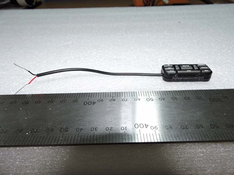
W75-RL-RCUIII
Aug 17, 2015Remote Control Unit
Equipment Class
DSC - Part 15 Security/Remote Control Transmitter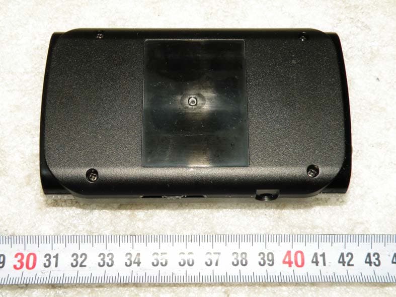
W75-RD950
Nov 06, 2014RADAR DETECTOR
Equipment Class
CRD - Part 15 Radar Detector
W75-RLS2
Nov 06, 2014RADAR DETECTOR
Equipment Class
CRD - Part 15 Radar Detector