WBQAQRFDM5DWATER/DUST PROOF MP3/IPOD DIGITAL MEDIA LOCKER
AQUATIC AV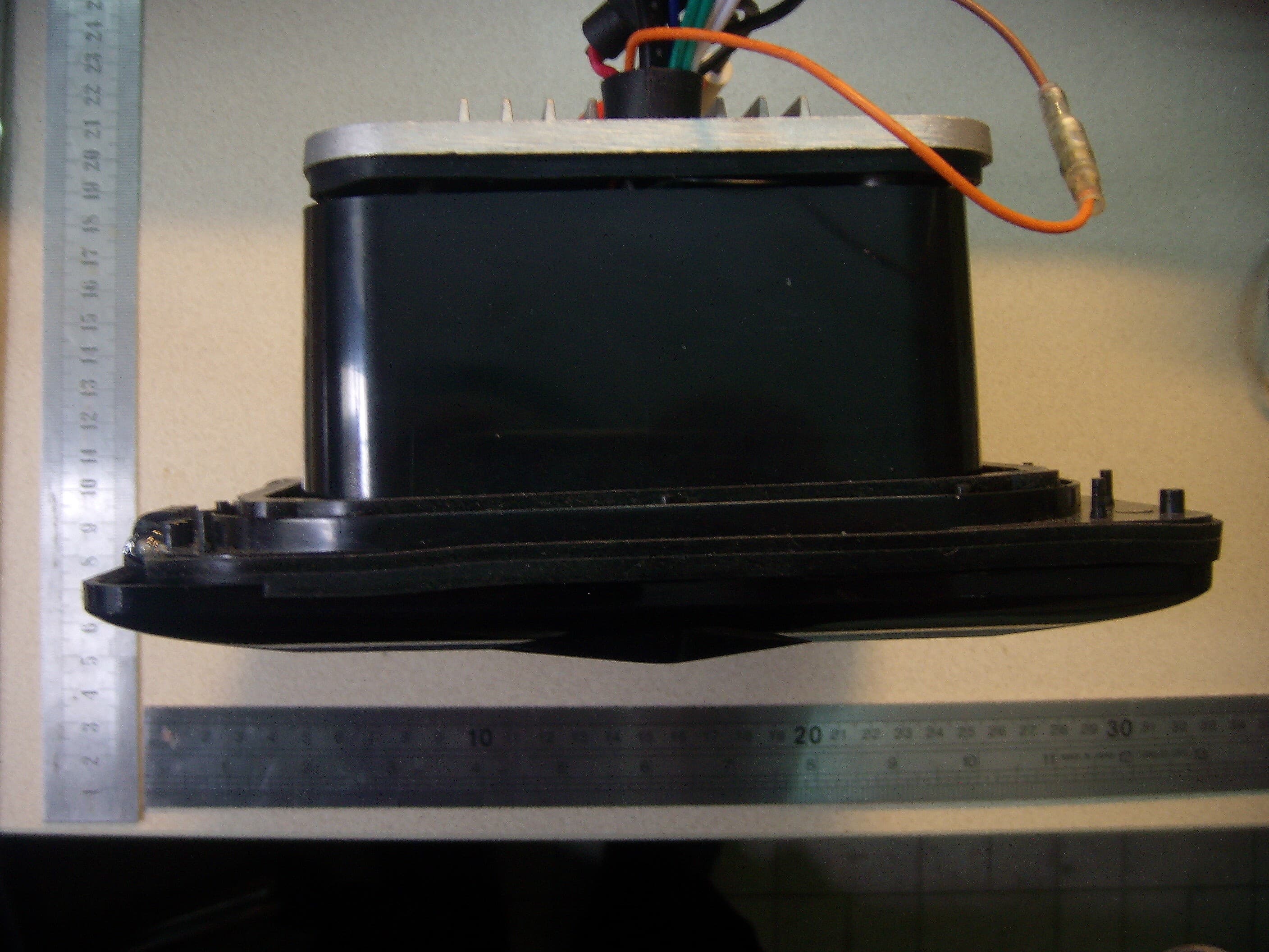
Click to zoom
Application Details
- Equipment Class
- DSS - Part 15 Spread Spectrum Transmitter
- Date of Grant
- Jan 20, 2014
- Application Purpose
- Original Equipment
- Date of Application
- Jan 20, 2014
- Equipment Note
- WATER/DUST PROOF MP3/IPOD DIGITAL MEDIA LOCKER
- Frequency Range
- 2402.00000000 - 2480.00000000
- Company
- AQUATIC AV
- Country
- United States
Documents & Files
Document Text
Text extracted from the exhibit documents filed with the FCC. Open a document above to read the original.
Users Manual
DIGITAL MEDIA LOCKER™ AQ-DM-5UBT OWNERSMANUAL DIGITAL MEDIA LOCKER ™ CONTENTS • AQ-DM-5UBT Digital Media Locker™ • 2-Way RF Wireless Remote Control (AQ-RFDM-5U) • 3.5mm to 3.5mm Jack Cable • Wiring Harness (AQ-UNH-2) optional • Six (6) Stainless Steel Mounting Screws • One (1) CR-2430 Battery • Mounting Template • Owner’s Manual INSTALLATION 1. 12-pin Watertight Harness The 12-pin harness supplies power and ground connections to the Digital Media Locker and four (4) speaker channel output connections from the Digital Media Locker. Do not cut or modify the 12-pin harness on the Locker side or warranty will be void. 2. FM Radio Antenna Jack Connect antenna (AQ-ANT-1 sold separately) to female antenna receptacle. For best FM performance make sure the antenna is exte nded to the highest achievable position. 3. Auxiliary Outputs Allows external amplifiers to be c onnected to power additional speakers. 4. 12V DC External Trigger Allows for an external light or rela y to be triggered (350mA max load). 5. Backlighting 12V DC input (orange) Allow to connect to an external 12V DC, light up LED backlight. 12-PIN HARNESS CONNECTION The AQ-DM-5UBT includes the universal ha rness AQ-UNH-2 in orde r to connect the dock to power and speakers. All open wire connections should be soldered and protected against water and dust for best long term performance. MOUNTING THE UNIT 1. Mounting templates is included. Aquatic AV recommends using the ‘measure twice, cut once’ method. 2. Once the mounting hole is complete, make sure the outside surface is clean and clear of debris. The Digital Media Locker has an external water/dust proof gasket, but this requires a clean surface for best performance. 3. The Digital Media Locker has six (6) front screws. Drive the screws using a screw driver. During final mounting apply equal pressure to all points for the best water/dust outer seal performance. 4. Review all outside surfaces of the Digital Media Locker to ensure proper water/dust seal. This is important for long term environmental protection performance for your digital media device. REMOTE BATTERY INSTALL Remove the RF Wireless Remote control from the Digital Media Locker. Unscrew the waterproof cap on the back of the remote control. Place the CR-2430 battery in the RF Remote control and replac e the water/dust proof cap. POWER ON Press the on/off button. Standby will be indicated by a red LED and ON by a blue LED. For applications that require lo w current draw and where battery drain may occur, the power button must be turned OFF. When the power button is in the OFF position the red LED will not be lit. For applications where a 12V battery is not used, such as in a Spa, the power button can be left ON and the remote control can then be used to power on/off accordingly. REMOTE SYNCHRONZING 1. Turn the Digital Media Locker to standby wi th the power button inside the door. The LED should illuminated red. 2. Press the red( ) button on the remote. 3. Press and hold the( ) button until the LCD reads PAIR. 4. Continue to press the ( ) button during step 5 below. 5. Turn the docking station stand by (within 10 seconds) with the on/off button inside door(the red LED will illuminate). 6. The remote’s LCD should read WELCOME or show a m ode position such as RADIO, BT or AUX IN. For any additional remote controls, you will also need to activate/synchronize those remote controls by following the steps above. If the pairing process is not effective, switch the locker off using the on/off button located inside the door of the dock. Unplug the 12-pin Ha rness on the back of the Locker for 3minutes. Reattach the Harness and repeat steps 1-6 above. If the LCD displays “NO LINK” in either mode, this means the remote is out of reception range. Move the remote closer to the Locker and try again. If you lose your remote control and buy another new remote control, please follow the above to start pairing before normal usage. DIGITAL MEDIA LOCKER 1. Digital Media Locker Open/Clo se Latch & Protective Door. 2. Power ON/OFF Button 3. Water/Dust Protection Inner Gasket 4. 3.5mm Aux Input for MP3 Devices 5. Power ON/OFF LED. 6. Security Strap for digital media devices. 7. Door Control Keypad. 8.LED Mode indicator. 9.Back lighting. DOOR CONTROL KEYPAD Buttons Music Mode FM Radio Mode Power Press once: Toggle from Operation mode to Standby mode or vice ‐ versa. Mode Press once: Change the source. Press once: Change the source Volume up + Press once: Volume up Press and hold: Fast volume up Press once: Volume up Press and hold: Fast volume up Volume Down ‐ Press once: Volume down Press and hold: Fast volume down Press once: Volume down Press and hold: Fast volume down Fast Rewind << Press once: Previous track Press and hold: Fast rewind Press once: Seek down Press and hold: Toggle manual scanning Fast Forward >> Press once: Next track Press and hold: Fast forward Press once: Seek up Press and hold: Toggle to manual scanning 12V Trigger/random Press once: Random playback function Press and hold: Toggle external 12V power on/off Press once: No function Press and hold: Toggle external 12V power on/off Play/pause Press once: Play/Pause Press and hold: Play/Pause Press once: Toggle mute Press and hold: Toggle mute 1/DIR ‐ 1 Press once: Back to previous folder Press and hold: Back to previous folder Press once: Listen to FM preset station 1 Press and hold: Set preset FM station 1 2/REPEAT 2 Press once: Repeat function Press and hold: Repeat function Press once: Listen to FM preset station 2 Press and hold: Set preset FM station 2 3/DIR+ 3 Press once: Forward to next folder Press and hold: Forward to next folder Press once: Listen to FM preset station 3 Press and hold: Set preset FM station 3 The keypad on the door has a set of keys fewer than those on the remote but has exactly the same functions correspondingly. This keypad a llows you to operate the dock even underno remote condition. REMOTE CONTROL Buttons Music Mode FM Radio Mode Power Press on…
Text truncated - open the document above for the full version.
Cover Letter(s)
AQUATIC AV 1476 Camden Avenue . Campbell, CA , Califomia United States .95008 18th November, 2013. Federal Communications Commission Authorization and Evaluation Division 7435 Oakland Mills Road Columbia, MD 21046. Confidentiality Request regarding application for certification of FCC ID: WBQAQRFDM5D. To Whom It May Concern: Pursuant to Sections 0.457 and 0.459 of the Commission’s Rules, we hereby request confidential treatment of information accompanying this application as outlined below: Exhibit T ype File Name Block Diagram WBQAQRFDM5D_BlockDiagram.pdf Schematic Diagram WBQAQRFDM5D_SchematicDiagram.pdf Circuit Description WBQAQRFDM5D_CircuitDescription.pdf Parts List WBQAQRFDM5D_PartsList.pdf La yout Drawing WBQAQRFDM5D_LayoutDrawing.pdf The above exhibits contain trade secrets and proprietary information not customarily released to the public. The public disclosure of these materials may be harmful to the applicant and provide unjustified benefits to its competitors. The applicant understands that pursuant to Section 0.457 of the Rules, disclosure of this application and all accompanying documentation will not be made before the date of the Grant for this application. Please do not hesitate to contact me if you have any queries. Yours faithfully, AQUATIC AV <SIGNATURE of Robert L. Fils> ----------------------------------------------------------------------------------- Robert L. Fils
Cover Letter(s)
AQUATIC AV 1476 Camden Avenue . Campbell, CA , Califomia United States .95008 FCC ID: WBQAQRFDM5D POWER OF ATTORNEY 18th November, 2013. Federal Communications Commission Authorization and Evaluation Division 7435 Oakland Mills Road Columbia, MD 21046. To Whom It May Concern: We, the undersigned, hereby authorize Gakkiku Technology Company (Dick Chan, Director), GTC Centre Limited (C.S. Lin, Manager Director) and Shenzhen SEM.Test Technology Co., Ltd. (Jandy So, Manager) on our behalf, to apply to the Federal Communications Commission on our equipment. Any and all acts carried out by Gakkiku Technology Company (Dick Chan, Director) on our behalf shall have the same effect as acts of our own. This authorization expires on 17th November, 2014. This is to advise that we are in full compliance with the Anti-Drug Abuse Act. We, AQUATIC AV, are not subject to a denial of federal benefits pursuant to Section 5301 of the Anti-Drug Act of 1988, 21 USC853a, and no party to the application is subject to a denial of federal benefits pursuant to that section. Please do not hesitate to contact me if you have any queries. Yours faithfully, AQUATIC AV <SIGNATURE of Robert L. Fils> ----------------------------------------------------------------------------------- Robert L. Fils
ID Label/Location Info
FCC ID LABLE Dock
Internal Photos
Top Side Bottom Side BT Module Top Side Bottom Side RF Module Main PCB
RF Exposure Info
RF Exposure Requirements Product Description: Water/Dust Proof MP3/iPod Digital Media Locker Model No.: AQ-DM-5UBT FCC ID: WBQAQRFDM5D According to the KDB 447498 D01 V05, the following RF exposure evaluation shall to demonstrate RF exposure compliance. BT Tx frequency range: 2402-2480MHz Device category: Portable device (Distance: 5mm) Maximum Conducted Output Power: 2.934 dBm Maximum Antenna Gain: 0 dBi Maximum EIRP Output Power: 1.9652 mW Limit: 10mW Source-based time-averaged EIRP output power is 1.9652 mW < 10 mW So the transmitter complies with the RF exposure requirements and the SAR is not required.
Test Report
AQUATIC AV Model No.: AQ-DM-5UBT REPORT NO.: STR13128002I-2 PAGE 1 OF 49 FCC PART 15.247 FCC Part 15C Measurement and Test Report For AQUATIC AV 282 Kinney Drive, San Jose, CA, 95112, United States FCC ID: WBQAQRFDM5D FCC Rule(s): FCC Part 15.247 Product Description: Water/Dust Proof MP3/iPod Digital Media Locker - Bluetooth Portion Tested Model: AQ-DM-5UBT Report No.: STR13128002I-2 Tested Date: 2013-12-06 to 2013-12-24 Issued Date: 2014-01-06 Tested By: Susan Su / Engineer Reviewed By: Lahm Peng / EMC Manager Approved & Authorized By: Jandy So / PSQ Manager Prepared By: Shenzhen SEM.Test Technology Co., Ltd. 1/F, Building A, Hongwei Industrial Park, Liuxian 2nd Road, Bao'an District, Shenzhen, P.R.C.(518101) Tel.: +86-755-33663308 Fax.: +86-755-33663309 Website: www.semtest.com.cn Note: This test report is limited to the above client company and the product model only. It may not be duplicated without prior permitted by Shenzhen SEM.Test Technology Co., Ltd. AQUATIC AV Model No.: AQ-DM-5UBT REPORT NO.: STR13128002I-2 PAGE 2 OF 49 FCC PART 15.247 TABLE OF CONTENTS 1. GENERAL INFORMATION ................................................................................................................................... 4 1.1 PRODUCT DESCRIPTION FOR EQUIPMENT UNDER TEST (EUT) ............................................................................... 4 1.2 TEST STANDARDS ................................................................................................................................................... 5 1.3 TEST METHODOLOGY ............................................................................................................................................. 5 1.4 TEST FACILITY ....................................................................................................................................................... 5 1.5 EUT SETUP AND TEST MODE ................................................................................................................................. 6 2. SUMMARY OF TEST RESULTS ........................................................................................................................... 7 3. RF EXPOSURE ......................................................................................................................................................... 8 3.1 STANDARD APPLICABLE ......................................................................................................................................... 8 3.2 TEST RESULT.......................................................................................................................................................... 8 4. ANTENNA REQUIREMENT .................................................................................................................................. 9 4.1 STANDARD APPLICABLE ......................................................................................................................................... 9 4.2 EVALUATION INFORMATION .................................................................................................................................. 9 5. FREQUENCY HOPPING SYSTEM REQUIREMENTS ................................................................................... 10 5.1 STANDARD APPLICABLE ....................................................................................................................................... 10 5.2 FREQUENCY HOPPING SYSTEM............................................................................................................................. 10 5.3 EUT PSEUDORANDOM FREQUENCY HOPPING SEQUENCE .................................................................................... 11 6. QUANTITY OF HOPPING CHANNELS AND CHANNEL SEPARATION ................................................... 12 6.1 STANDARD APPLICABLE ....................................................................................................................................... 12 6.2 TEST EQUIPMENT LIST AND DETAILS ................................................................................................................... 12 6.3 TEST PROCEDURE ................................................................................................................................................. 12 6.4 ENVIRONMENTAL CONDITIONS ............................................................................................................................ 12 6.5 SUMMARY OF TEST RESULTS/PLOTS .................................................................................................................... 13 7. DWELL TIME OF HOPPING CHANNEL .......................................................................................................... 17 7.1 STANDARD APPLICABLE ....................................................................................................................................... 17 7.2 TEST EQUIPMENT LIST AND DETAILS ................................................................................................................... 17 7.3 TEST PROCEDURE ................................................................................................................................................. 17 7.4 ENVIRONMENTAL CONDITIONS ............................................................................................................................ 17 7.5 SUMMARY OF TEST RESULTS/PLOTS .................................................................................................................... 18 8. 20DB BANDWIDTH ............................................................................................................................................... 28 8.1 STANDARD APPLICABLE ....................................................................................................................................... 28 8.2 TEST EQUIPMENT LIST AND DETAILS .......................…
Text truncated - open the document above for the full version.
Test Setup Photos
AQUATIC AV Model: AQ-DM-5UBT REPORT NO.: STR13128002I-1/2 FCC PART 15.247 & 15.249 EXHIBIT 4 - TEST SETUP PHOTOGRAPHS Radiation Emission Test Setup (Below 30MHz) Radiation Emission Test Setup (30MHz to 1GHz) AQUATIC AV Model: AQ-DM-5UBT REPORT NO.: STR13128002I-1/2 FCC PART 15.247 & 15.249 Radiation Emission Test Setup (Above 1GHz)
Contact Information
Applicant
Robert L. Fils
Test Firm
SEM.Test Compliance Service Co., Ltd.Jandy So
Technical Specifications
| # | Rule Parts | Frequency Range | Power Output |
|---|---|---|---|
| 1 | 15C | 2.40 GHz - 2.48 GHz | 2.00 mW |
Other Applications from AQUATIC AV

WBQ-SWA6MINI
Feb 02, 2021Bluetooth Subwoofer with Power Supply
Equipment Class
DSS - Part 15 Spread Spectrum Transmitter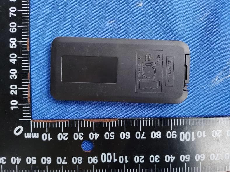
WBQCS9016
Nov 23, 2020RGB RF remote
Equipment Class
DSC - Part 15 Security/Remote Control Transmitter
WBQ6500-915
Nov 23, 2015SPA Stereo System
Equipment Class
DSS - Part 15 Spread Spectrum Transmitter
WBQ-SM78
May 07, 2015WATERPROOF MEDIA PLAYER
Equipment Class
DSS - Part 15 Spread Spectrum Transmitter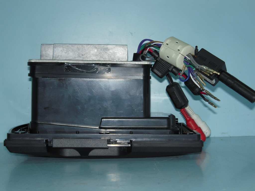
WBQAQRFDM4D
Jan 16, 2013Water/Dust Proof MP3 / iPod Digital Media Locker with Floating RF LCD 2-way RC
Equipment Class
DXX - Part 15 Low Power Communication Device Transmitter