WBV-BR200-WPAP Router
Aerohive Networks, Inc.
Click to zoom
Application Details
- Equipment Class
- DTS - Digital Transmission System
- Date of Grant
- Feb 14, 2012
- Application Purpose
- Original Equipment
- Date of Application
- Feb 14, 2012
- Equipment Note
- AP Router
- Frequency Range
- 5745.00000000 - 5825.00000000
- Company
- Aerohive Networks, Inc.
- Country
- United States
Documents & Files
Document Text
Text extracted from the exhibit documents filed with the FCC. Open a document above to read the original.
Users Manual
Operating Instructions Manual Model Name: BR200-WP Model No., BR200-WP AC/DC power Adapter Rating: 48Vdc, 1.25A Operating Temperature: 32 to 104 degrees F (0C to 40 degrees C) Storage Temperature: -4 to 158 degrees F (-20 to 70 degrees C Relative Humidity: Maximum 95% Contact for software questions: [email protected] Phone: 408-510-6100 Needed Equipment: Ethernet hub. Laptops AP login information: Serial connection: 9800, 8, N, 1, no flow control Login: admin Password: aerohive Must have the Ethernet port connected so the EUT gets active link. Must enter line commands to set channel, power and mode. Wifi1 – 5GHz radio Wifi0 – 2.4GHz radio In the instructions below, enter the correct wifi1 or wifi0 for the appropriate band you are testing. To display available channels: show interface <wifi0 | wifi1> channel To set channel: interface <wifi0 | wifi1 > radio channel XX <- 2.4GHz or 5G to channel XX To set power: interface <wifi0 | wifi1> radio power XX <-- sets 2.4GHz/5G radio to power XX, note if power XX is greater than the systems internal power limit for japan, it will set power to the limit To change between 20MHz and 40MHz operation, need to load/change the operation radio profiles: radio profile 11na channel-width 40-above <-- will set the 5GHz radio to 40MHz operation, with the extra 20MHz emission located above the current channel. Example – if the current channel is set to channel 36, and you bond the channel above, then the center of the emission will be channel 38 To reset the channel to 20MHz: radio profile 11na channel-width 20 Profile – 11na – 5GHz profile Profile – 11ng – 2.4GHz operation profile To see the radio’s current settings: show interface <wifi0 | wifi1> To see the radio per chain power setting: Show interface <wifi0 | wifi1> _per To see a list of radio profiles and SSID’s for the radios (need below): show int <- table showing radio status show run shows list of profiles To create a SSID, and make it operational on 2.4/5G radio: Ssid jpn_dfs Interface <wifi0 | wifi1> ssid jpn_dfs To turn off a radio (not RX mode) Interface wifi0 SSID jpn_dfs shutdown To bring the radio back up no interface wifi0 SSID jpn_dfs shutdown To start continuous transmission: _test interface wifi tx-chain-mask YY cont-tx XX payload-size 1500 Must use _ before test Must set channel, power and bandwith first YY = 0x1 for single chain, or 0x3 for both chains (use this!) XX = data rate in 500kB/s. (For legacy modes – take the normal data rate and double it, for example, 802.11b 1Mbs/s – enter in 2, for 802.11g, 11Mb/s – enter in 22; or enter in MCS#) Examples: 802.11b, 1Mbs both chains): _test interface wifi0 tx-chain-mask 0x3 cont-tx 2 payload- size 1500 802.11g, 6Mbs: _test interface wifi tx-chain-mask 0x3 cont-tx 12 payload-size 1500 802.11n20, MCS0: _test interface wifi tx-chain-mask 0x3 cont-tx mcs0 payload-size 1500 To stop transmission: no _test interface wifi0 cont-tx Must stop transmission before changing any other parameters. RX Mode: _test interface wifi0 rx-only To stop RX mode: No _test interface wifi0 rx-only DFS Instructions Need: DFS client laptop Setup the DFS client to fixed IP address: 192.168.1.3 Set the channel and bandwidth using the radio commands shown previously Once the client laptop associates with the AP, confirm that you can ping the laptop wired to the AP. On client laptop, open file explorer, then connect the laptop on the wired side to find out the FCC video, and then double click the video file to start the VLC playing session. To control the data rate while stream: ssid jpn_dfs 11a-rate-set XX ssid jpn_dfs 11n-mcs-rate-set XX This will set the maximum data rate, system can auto negotiate at a lower rate. EUT Laptop (192.168.1.2) – VLC server POE ENET Switch Serial AC DFS client (192.168.1.3) ethernet ethernet
Users Manual
© 2011 Aerohive Networks, Inc. All rights reserved. 330033-11 Rev. B Aerohive HiveAP Compliance Information Federal Communication Commission Interference Statement Aerohive products (FCC models, AH-AP-110-N-FCC, AH-AP-120-N-FCC, AH-AP-170-N-FCC, AH-AP-320-N-FCC, AH-AP-330-N-FCC, AH-AP-340-N-FCC , AH-AP-350-N-FCC, AH-BR100-N-FCC,AH-BR200-WP-N-FCC) comply with part 15 of the FCC Rules when operating under the following restrictions: (1) they do not cause harmful interference, and (2) they must accept any RF interference received, including interference that might cause an unwanted impact on their operation. This equipment has been tested and found to comply with the limits for a Class B digital device, pursuant to Part 15 of the FCC Rules. These limits are designed to provide reasonable protection against harmful interference in a residential installation. This equipment generates uses and can radiate radio frequency energy and, if not installed and used in accordance with the instructions, may cause harmful interference to radio communications. However, there is no guarantee that interference will not occur in a particular installation. If this equipment does cause harmful interference to radio or television reception, which can be determined by turning the equipment off and on, the user is encouraged to try to correct the interference by one of the following measures: • Reorient or relocate the receiving antenna • Increase the separation between the equipment and receiver • Connect the equipment into an outlet on a circuit different from that to which the receiver is connected • Consult the dealer or an experienced radio/TV technician for help FCC Caution: Any changes or modifications not expressly approved by the party responsible for compliance could void the user's authority to operate this equipment. This device complies with Part 15 of the FCC Rules. Operation is subject to the following two conditions: (1) This device may not cause harmful interference, and (2) this device must accept any interference received, including interference that may cause undesired operation. In compliance with FCC Part 15 regulations, the HiveAP automatically discontinues transmission if there is no valid information to transmit or if there is an operational failure. Important: FCC Regulatory Warning Notices HiveAP 110, 120, 320, 330, 340, 350 devices are restricted to indoor use due to their operation in 5 GHz frequencies, which are shared by mobile satellite systems and government radar systems. The FCC requires that these products only be used indoors to reduce the potential for harmful interference with co-channel radar that might be operating in the 5.25-5.35 or 5.47-5.725 GHz frequency ranges in the same area. The conflicting activity of radar stations and these devices can cause interference or damage to each other. In addition, these devices have a radar detection function that might interrupt normal operations when they detect a radar signal. To reduce the risk of interference even further, installing these devices away from windows is recommended. HiveAP 170 devices operating within the 5.15-5.25 GHz frequency range are restricted to indoor environments. The FCC region code is set in the device during the manufacturing process, the option to set it to any region other than FCC is disabled, and the country code selection function has been completely removed from all U.S. models. It is impossible for the end user to change the region to anything other than FCC. FCC Radiation Exposure Statement This equipment complies with FCC radiation exposure limits set forth for an uncontrolled environment. This equipment should be installed and operated with a minimum distance of 20 centimeters (8 inches) between the radiator and your body. This transmitter must not be co-located or operating in conjunction with any other antenna or transmitter. The availability of some specific channel and/or operational frequency bands are country dependent and are firmware programmed at the factory to match the intended destination. The firmware setting is not accessible by end user. Only attach antennas that are certified for use with this device. Replacing antennas with unauthorized, high-gain antennas greatly increases the risk of interference and invalidates the FCC certification. Industry Canada Note: The term "IC" before the radio certification number signifies that Industry Canada technical specifications were met. Products that show an Industry Canada identifier on the product label (IC HiveAP 170, 320, 330, 340, 350, BR100, BR200 and BR200-WP) can be operated in Canada under the following restrictions: This device complies with RSS-210 of the Industry Canada Rules. Operation is subject to the following two conditions: (1) This device may not cause harmful interference, and (2) this device must accept any interference received, including interference that may cause undesired operation. IMPORTANT NOTE: IC Radiation Exposure Statement Radiation Exposure Statement: This equipment complies with IC radiation exposure limits set forth for an uncontrolled environment. This equipment should be installed and operated with a minimum distance of 20 cm between the radiator and your body. For the models using “detachable Antenna” The HiveAP 170/350 has been designed to operate with an antenna having a Dipole maximum gain 5dBi. Antenna having a higher gain is strictly prohibited per regulations of Industry Canada. The required antenna impedance is 50 ohms. Under Industry Canada regulations, this radio transmitter may only operate using an antenna of a type and maximum (or lesser) gain approved for the transmitter by Industry Canada. To reduce potential radio interference to other users, the antenna type and its gain should be so chosen that the equivalent isotropically radiated power (E.I.R.P) is not more than that necessary for successful communication. This radio transmitter has been approved by Industry Canada to operate with…
Text truncated - open the document above for the full version.
Cover Letter(s)
330 Gibraltar Drive, Sunnyvale, CA 94089 TEL: +1-408-510-6100 ; FAX: +1-408-510-6199 Date: 2012-02-10 FCC ID: WBV‐BR200‐WP To the Attention of: Federal Communications Commission Authorization and Evaluation Division Confidentiality Request Pursuant to Sections 0.457 and 0.459 of the Commission’s Rules, the Applicant hereby requests confidential treatment of information accompanying this Application as outlined below: Schematics Block Diagram Operation Description The above materials contain trade secrets and proprietary information not customarily released to the public. The public disclosure of these matters might be harmful to the Applicant and provide unjustified benefits to its competitors. The Applicant understands that pursuant to Rule 0.457, disclosure of this Application and all accompanying documentation will not be made before the date of the Grant for this application. Sincerely yours, Serdar Ergene Director, HW Engineering Aerohive Networks, Inc. TEL: +1-408-510-6103 FAX: +1-408-510-6199 E-mail: [email protected]
Internal Photos
Page 4 Page 5 Page 6 Page 7 Page 8 Page 9 Page 10 Page 11
RF Exposure Info
Report No.: SA111222C15 1 Report Format Version 4.0.0 RF EXPOSURE REPORT REPORT NO.: SA111222C15 MODEL NO.: BR200-WP FCC ID: WBV-BR200-WP RECEIVED: Dec. 22, 2011 TESTED: Jan. 03 ~ Jan. 18, 2012 ISSUED: Jan. 30, 2012 APPLICANT: Aerohive Networks, Inc. ADDRESS: 330 Gibraltar Drive, Sunnyvale, CA 94089 ISSUED BY: Bureau Veritas Consumer Products Services (H.K.) Ltd., Taoyuan Branch LAB ADDRESS: No. 47, 14th Ling, Chia Pau Vil., Lin Kou Dist., New Taipei City, Taiwan ( R.O.C ) TEST LOCATION: No. 19, Hwa Ya 2nd Rd, Wen Hwa Tsuen, Kwei Shan Hsiang, Taoyuan Hsien 333, Taiwan, R.O.C. This test report consists of 6 pages in total. It may be duplicated completely for legal use with the approval of the applicant. It should not be reproduced except in full, without the written approval of our laboratory. The client should not use it to claim product certification, approval or endorsement by any government agency. The test results in the report only apply to the tested sample. Report No.: SA111222C15 2 Report Format Version 4.0.0 TABLE OF CONTENTS RELEASE CONTROL RECORD.............................................................................................3 1. CERTIFICATION..........................................................................................................4 2. RF EXPOSURE ...........................................................................................................5 2.1 LIMITS FOR MAXIMUM PERMISSIBLE EXPOSURE (MPE) .....................................5 2.2 MPE CALCULATION FORMULA.................................................................................5 2.3 CLASSIFICATION .......................................................................................................5 2.4 CACLULATION RESULT OF MAXIMUM CONDUCTED POWER ..............................6 Report No.: SA111222C15 3 Report Format Version 4.0.0 RELEASE CONTROL RECORD ISSUE NO. REASON FOR CHANGE DATE ISSUED Original release NA Jan. 30, 2012 Report No.: SA111222C15 4 Report Format Version 4.0.0 1. CERTIFICATION PRODUCT: AP Router MODEL: BR200-WP BRAND: Aerohive APPLICANT: Aerohive Networks, Inc. TESTED: Jan. 03 ~ Jan. 18, 2012 TEST SAMPLE: ENGINEERING SAMPLE STANDARDS: FCC Part 2 (Section 2.1091) FCC OET Bulletin 65, Supplement C (01-01) IEEE C95.1 The above equipment (Model: BR200-WP) has been tested by Bureau Veritas Consumer Products Services (H.K.) Ltd., Taoyuan Branch, and found compliance with the requirement of the above standards. The test record, data evaluation & Equipment Under Test (EUT) configurations represented herein are true and accurate accounts of the measurements of the sample’s EMC characteristics under the conditions specified in this report. PREPARED BY : , DATE:Jan. 30, 2012 Ivy Lin / Specialist APPROVED BY : , DATE:Jan. 30, 2012 Cody Chang / Manager Report No.: SA111222C15 5 Report Format Version 4.0.0 2. RF EXPOSURE 2.1 LIMITS FOR MAXIMUM PERMISSIBLE EXPOSURE (MPE) FREQUENCY RANGE (MHz) ELECTRIC FIELD STRENGTH (V/m) MAGNETIC FIELD STRENGTH (A/m) POWER DENSITY (mW/cm 2 ) AVERAGE TIME (minutes) LIMITS FOR GENERAL POPULATION / UNCONTROLLED EXPOSURE 300-1500 ... ... F/1500 30 1500-100,000 ... ... 1.0 30 F = Frequency in MHz 2.2 MPE calculation Formula Pd = (Pout*G) / (4*pi*r2) where Pd = power density in mW/cm2 Pout = output power to antenna in mW G = gain of antenna in linear scale Pi = 3.1416 R = distance between observation point and center of the radiator in cm 2.3 CLASSIFICATION The antenna of this product, under normal use condition, is at least 20cm away from the body of the user. So, this device is classified as Mobile Device. Report No.: SA111222C15 6 Report Format Version 4.0.0 2.4 CACLULATION RESULT OF MAXIMUM CONDUCTED POWER FREQUENCY BAND (MHz) MAX POWER (dBm) ANTENNA GAIN (dBi) DISTANCE (cm) POWER DENSITY (mW/cm 2 ) LIMIT (mW/cm 2 ) 2412-2462 29.44 1.91 20 0.271 1 5180-5240 16.82 2.76 20 0.018 1 5745-5825 27.81 2.51 20 0.214 1
Test Report
Report No.: RF111222C15 1 Report Format Version 4.1.0 FCC TEST REPORT (15.247) REPORT NO.: RF111222C15 MODEL NO.: BR200-WP FCC ID: WBV-BR200-WP RECEIVED: Dec. 22, 2011 TESTED: Jan. 03 ~ Jan. 18, 2012 ISSUED: Jan. 30, 2012 APPLICANT: Aerohive Networks, Inc. ADDRESS: 330 Gibraltar Drive, Sunnyvale, CA 94089 ISSUED BY: Bureau Veritas Consumer Products Services (H.K.) Ltd., Taoyuan Branch LAB ADDRESS: No. 47, 14th Ling, Chia Pau Vil., Lin Kou Dist., New Taipei City, Taiwan ( R.O.C ) TEST LOCATION: No. 19, Hwa Ya 2nd Rd, Wen Hwa Tsuen, Kwei Shan Hsiang, Taoyuan Hsien 333, Taiwan, R.O.C. This test report consists of 82 pages in total. It may be duplicated completely for legal use with the approval of the applicant. It should not be reproduced except in full, without the written approval of our laboratory. The client should not use it to claim product, certification, approval or endorsement by TAF or any government agency. The test results in the report only apply to the tested sample. Report No.: RF111222C15 2 Report Format Version 4.1.0 TABLE OF CONTENTS RELEASE CONTROL RECORD..........................................................................................5 1. CERTIFICATION.......................................................................................................6 2. SUMMARY OF TEST RESULTS ..............................................................................7 2.1 MEASUREMENT UNCERTAINTY ...........................................................................7 3. GENERAL INFORMATION .......................................................................................8 3.1 GENERAL DESCRIPTION OF EUT.........................................................................8 3.2 DESCRIPTION OF TEST MODES.........................................................................10 3.2.1 CONFIGURATION OF SYSTEM UNDER TEST .................................................... 11 3.2.2 TEST MODE APPLICABILITY AND TESTED CHANNEL DETAIL .........................12 3.3 GENERAL DESCRIPTION OF APPLIED STANDARDS ........................................16 3.4 DESCRIPTION OF SUPPORT UNITS ...................................................................16 4. TEST TYPES AND RESULTS (FOR 2.4GHz BAND).............................................17 4.1 RADIATED EMISSION AND BANDEDGE MEASUREMENT.................................17 4.1.1 LIMITS OF RADIATED EMISSION AND BANDEDGE MEASUREMENT ..............17 4.1.2 TEST INSTRUMENTS ...........................................................................................18 4.1.3 TEST PROCEDURES ............................................................................................19 4.1.4 DEVIATION FROM TEST STANDARD ..................................................................19 4.1.5 TEST SETUP .........................................................................................................20 4.1.6 EUT OPERATING CONDITIONS ...........................................................................20 4.1.7 TEST RESULTS .....................................................................................................21 4.2 CONDUCTED EMISSION MEASUREMENT .........................................................34 4.2.1 LIMITS OF CONDUCTED EMISSION MEASUREMENT.......................................34 4.2.2 TEST INSTRUMENTS ...........................................................................................34 4.2.3 TEST PROCEDURES ............................................................................................35 4.2.4 DEVIATION FROM TEST STANDARD ..................................................................35 4.2.5 TEST SETUP .........................................................................................................36 4.2.6 EUT OPERATING CONDITIONS ...........................................................................36 4.2.7 TEST RESULTS .....................................................................................................37 4.3 6dB BANDWIDTH MEASUREMENT .....................................................................39 4.3.1 LIMITS OF 6dB BANDWIDTH MEASUREMENT ...................................................39 4.3.2 TEST SETUP .........................................................................................................39 4.3.3 TEST INSTRUMENTS ...........................................................................................39 4.3.4 TEST PROCEDURE ..............................................................................................39 4.3.5 DEVIATION FROM TEST STANDARD ..................................................................39 4.3.6 EUT OPERATING CONDITIONS ...........................................................................39 4.3.7 TEST RESULTS .....................................................................................................40 4.4 CONDUCTED OUTPUT POWER ..........................................................................41 4.4.1 LIMITS OF CONDUCTED OUTPUT POWER MEASUREMENT ...........................41 4.4.2 TEST SETUP .........................................................................................................41 4.4.3 TEST INSTRUMENTS ...........................................................................................41 4.4.4 TEST PROCEDURES ............................................................................................41 4.4.5 DEVIATION FROM TEST STANDARD ..................................................................41 Report No.: RF111222C15 3 Report Format Version 4.1.0 4.4.6 EUT OPERATING CONDITIONS ...........................................................................41 4.4.7 TEST RESULTS .....................................................................................................42 4.5 POWER SPECTRAL DENSITY MEASUREMENT.................................................43 4.5.1 LIMITS OF POWER SPECTRAL DENSITY MEASUREMENT ..…
Text truncated - open the document above for the full version.
Test Setup Photos
1 PHOTOGRAPHS OF THE TEST CONFIGURATION CONDUCTED EMISSION TEST 2 RADIATED EMISSION TEST
Contact Information
Applicant
Tim Wakeley(Compliance Manager)
Technical Contact
Bureau Veritas CPS (H.K.) Ltd. Taoyuan BranchGary Chang
[email protected]886-3-3183232
No. 19, Hwa Ya 2nd Rd., Kwei Shan Hsiang · Taoyuan Hsien · Taiwan
Non-Technical Contact
Bureau Veritas CPS (H.K.) Ltd. Taoyuan BranchNatacha Chen
[email protected]886-3-3183232
Test Firm
Bureau Veritas CPS (H.K.) Ltd. Taoyuan BranchRichard Chen
Technical Specifications
| # | Rule Parts | Frequency Range | Power Output |
|---|---|---|---|
| 2 | 15C | 5.75 GHz - 5.83 GHz | 604.00 mW |
Other Applications from Aerohive Networks, Inc.

WBV-AP130
Feb 11, 2015Access Point
Equipment Class
DTS - Digital Transmission System
WBV-AP1130
Nov 24, 2014Access Point
Equipment Class
DTS - Digital Transmission System
WBV-BR200-WPL
May 15, 2014AP Router
Equipment Class
DTS - Digital Transmission System
WBV-AP230
Mar 18, 2014Access Point
Equipment Class
DTS - Digital Transmission System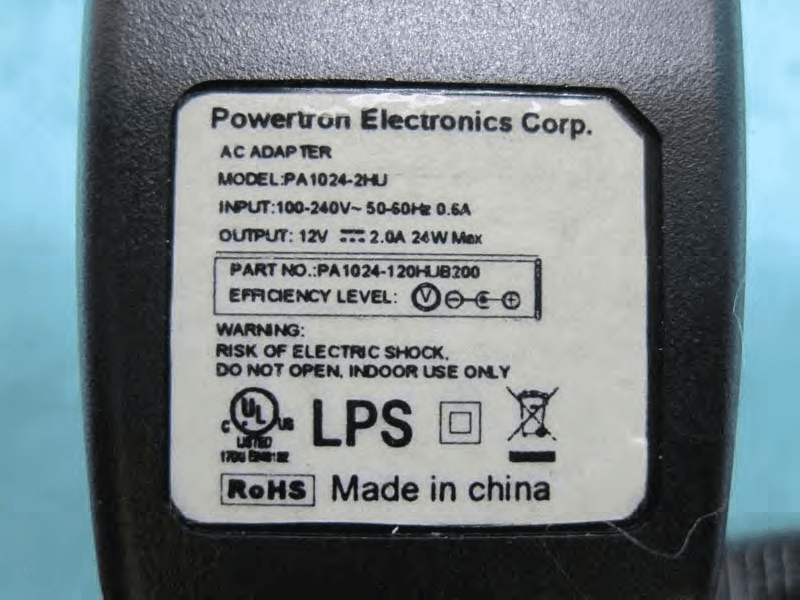
WBV-AP3X0
Aug 28, 2013Access Point
Equipment Class
NII - Unlicensed National Information Infrastructure TX