WBV-HIVEAP170Wireless Access Points
Aerohive Networks, Inc.
Click to zoom
Application Details
- Equipment Class
- NII - Unlicensed National Information Infrastructure TX
- Date of Grant
- Sep 19, 2011
- Application Purpose
- Original Equipment
- Date of Application
- Sep 19, 2011
- Equipment Note
- Wireless Access Points
- Frequency Range
- 5180.00000000 - 5240.00000000
- Company
- Aerohive Networks, Inc.
- Country
- United States
Documents & Files
Document Text
Text extracted from the exhibit documents filed with the FCC. Open a document above to read the original.
Users Manual
P/N 330052-01, Rev. A1 HIVEAP 170 INSTALLATION GUIDE This guide explains how to mount a HiveAP 170 to a pole or flat surface in virtually any outdoor setting, and connect it to HiveManager over the network. To register, get product documentation, see compliance information, and download software updates, visit www.aerohive.com/support . KIT CONTENTS, REQUIRED ACCESSORIES, AND TOOLS The HiveAP 170 kit includes the items shown in Figure 1. Figure 1 HiveAP 170 kit contents To install your HiveAP 170, you will need the following accessories (ordered separately) and tools: •(2) 2.4 GHz antennas (AH-ACC-170-ANT-2G) •(2) 5 GHz antennas (AH-ACC-170-ANT-5G) •A switch that provides PoE power, or a PoE provisioning device •(1) shielded cat5 Ethernet cable rated for outdoor use; length not to exceed 328 feet (100 m) •Crosshead screwdriver for 1/4” (6 mm) x 3/8” (10 mm) screws •Drive sockets (nut drivers) for 3/8” (10 mm) nuts •Flat blade screwdriver to tighten hose clamp SAFETY INSTRUCTIONS AND SITE HAZARD WARNINGS Read and follow these safety instructions and hazard warnings before installing a HiveAP 170 outdoors. Keep these instructions for future reference. •To comply with RF (radio frequency) exposure limits, do not place the HiveAP 170 within 8" (20 cm) of people. •You can install the HiveAP 170 in wet, windy locations. Therefore, make sure to install the Ethernet cable housing for a complete waterproof connection. •To protect the HiveAP 170 from lightning, do not place it at the highest point of a building or structure. Plane Bracket (1) HiveAP 170 Base Bracket (1) (4) Sleeve-Bolt Assembly Sleeve, 5/8” (16 mm), Bolt 1 15/16” (5 cm), Hex nut 3/8” (10 mm), Washer 5/8” (16 mm) (4) Round Head Screw 1/4” (6 mm) Lock Washer, Flat Washer (4) Hex Head Bolt, 3/8”x1/2” (10 mm x 13 mm) Lock Washer, Flat Washer 1/2” (13 mm) Hose Strap (1) Ground Cable (1) Ethernet Housing (1) Aerohive Networks 2 DEVICE, POWER, AND ENVIRONMENTAL SPECIFICATIONS Understanding the range of specifications for the HiveAP 170 is necessary for optimal deployment and device operation. The following specifications describe the hardware components, PoE (Power over Ethernet) electrical requirements, and the environmental ranges in which the device can operate. Device and Enclosure Specifications •HiveAP dimensions (without antennas): 9 5/8” long x 7 7/8” wide x 3" high (22.4 cm x 20 cm x 7.6 cm) •HiveAP weight: 4.85 lb. (2.199 kg) with antennas, 6.05 lb (2.744 kg) with antennas and brackets •Antennas: 4 N-type female connectors for external antennas •Ethernet connector: autosensing 10/100/1000 Base-T Mbps; compliant with the IEEE 802.3at standard for PoE •Mounting options: •Horizontal or vertical pole mount; pole must be 1" to 3.5" (2.5 cm to 8.9 cm) in diameter •Wall or flat surface mount Power Specifications •PoE nominal input voltages: 48 V, 30 watts Environmental Specifications •Operating temperature: -40 to 131 degrees F (-40 to 55 degrees C) •Storage temperature: -40 to 176 degrees F (-40 to 80 degrees C) •Relative humidity: Maximum 100% •Wind survivability: > 165 mph (266 kph) •Environmental compliance: IP68 Make sure that the HiveAP 170 is connected to a suitably installed ground conductor. Contact the appropriate electrical inspection authority if you are uncertain that suitable grounding is available. Do not locate the HiveAP 170 enclosure near overhead power lines or other electric light or power circuits, or where it can come into contact with such circuits. During installation, exercise extreme care not to come into contact with these circuits, which can cause serious injury or death. For proper installation and grounding of the product, refer to national and local electrical codes: NFPA (National Fire Protection Association) 70, National Electrical Code Article 810 (U.S.); Canadian Electrical Code, Part I, CSA 22.1 and Section 54 (Canada); and if local or national electrical codes are not available, refer to IEC (International Electrotechnical Commission) 364, Part 1 through 7 (other countries). Do not connect or disconnect antennas or cables from the HiveAP 170 during periods of lightning activity. To install the HiveAP 170, you must be a qualified installation professional, licensed or certified in accordance with local regulations. Use only attachments and accessories specified by Aerohive. During operation, the surfaces of the HiveAP 170 can become hot. Use caution when handling it. 3 Aerohive Networks MOUNTING THE HIVEAP 170 You can mount the HiveAP 170 on a variety of outdoor structures and adjust the orientation to vertical for optimum radio transmission. For example, you can mount the HiveAP 170 on a non-penetrating roof stand or to a Winegard bracket, often used for mounting satellite dishes. The mounting bracket is adjustable to fit poles with a 1" to 3.5" (2.5 cm to 8.9 cm) diameter. To provide unobstructed RF coverage, mount the HiveAP 170 in a relatively open area. At a minimum, mount it on a pole, mast, of flat surface so that the antennas have at least a three-foot clearance from any nearby obstructions. After checking that you have all the materials and tools necessary, and familiarizing yourself with the safety and site hazard warnings, you are ready to mount the unit. You can mount the HiveAP 170 on a vertical or horizontal pole, or attach it to a flat surface. These options are described below. The device and mounting accessories required for mounting the HiveAP 170 are shown in Figure 2. Figure 2 HiveAP 170 mounted on a vertical pole with major devices and accessories called out PoE Connections In most cases, you can connect an Ethernet cable directly from your HiveAP 170 to a PoE-enabled switch, or to a PoE injector inside the building (see Figure 2). If you are not using a PoE-enabled switch, you must connect to an intermediary PoE injector, then to your switch (see Figure 4 on page 8). In cases where your HiveAP 170 is located a significant distance from the building, you can install an outdoor w…
Text truncated - open the document above for the full version.
Users Manual
© 2011 Aerohive Networks, Inc. All rights reserved. 330033-08 Rev. A Aerohive HiveAP Compliance Information Federal Communication Commission Interference Statement Aerohive products that show an FCC identifier on the product label ( FCC models, AH-AP-110-N-FCC, AH-AP-120-N-FCC, AH-AP-170-N-FCC, AH-AP-320-N-FCC, AH-AP-330-N-FCC, AH-AP-340-N-FCC ,AH-AP-350-N-FCC) comply with part 15 of the FCC Rules when operating under the following restrictions: (1) they do not cause harmful interference, and (2) they must accept any RF interference received, including interference that might cause an unwanted impact on their operation. This equipment has been tested and found to comply with the limits for a Class B digital device, pursuant to Part 15 of the FCC Rules. These limits are designed to provide reasonable protection against harmful interference in a residential installation. This equipment generates uses and can radiate radio frequency energy and, if not installed and used in accordance with the instructions, may cause harmful interference to radio communications. However, there is no guarantee that interference will not occur in a particular installation. If this equipment does cause harmful interference to radio or television reception, which can be determined by turning the equipment off and on, the user is encouraged to try to correct the interference by one of the following measures: • Reorient or relocate the receiving antenna • Increase the separation between the equipment and receiver • Connect the equipment into an outlet on a circuit different from that to which the receiver is connected • Consult the dealer or an experienced radio/TV technician for help FCC Caution: Any changes or modifications not expressly approved by the party responsible for compliance could void the user's authority to operate this equipment. This device complies with Part 15 of the FCC Rules. Operation is subject to the following two conditions: (1) This device may not cause harmful interference, and (2) this device must accept any interference received, including interference that may cause undesired operation. In compliance with FCC Part 15 regulations, the HiveAP automatically discontinues transmission if there is no valid information to transmit or if there is an operational failure. Important: FCC Regulatory Warning Notices HiveAP 110, 120, 320, 330, 340, and 350 devices are restricted to indoor use due to their operation in 5 GHz frequencies, which are shared by mobile satellite systems and government radar systems. The FCC requires that these products only be used indoors to reduce the potential for harmful interference with co-channel radar that might be operating in the 5.25-5.35 or 5.47-5.725 GHz frequency ranges in the same area. The conflicting activity of radar stations and these devices can cause interference or damage to each other. In addition, these devices have a radar detection function that might interrupt normal operations when they detect a radar signal. To reduce the risk of interference even further, installing these devices away from windows is recommended. HiveAP 170 devices operating within the 5.15-5.25 GHz frequency range are restricted to indoor environments. DFS certification for Aerohive products is underway but is not complete at the time of this writing. Contact Aerohive Technical Support for further information. After DFS certification is complete, these statements will hold true: This equipment complies with the FCC DFS (Dynamic Frequency Selection) rules documented in FCC 06-96 and KDB 443999. The 5 GHz radio uses channels 36 to 48 (5.180 to 5.240 GHz) and channels 149 to 165 (5.725 to 5.825 GHz), as well as channels within the DFS operating frequency ranges: 52 to 64 (5.25 to 5.35 GHz), 100 to 116 (5.47 to 5.59 GHz), and 132 to 140 (5.66 to 5.725 GHz). The frequency range 5.6 - 5.65 GHz is excluded from use. The maximum transmit power for channels from 36 to 48 is 15 dBm in the FCC region. Because this maximum is enforced by HiveOS, the HiveAP automatically limits the power to 15 dBm even if the setting is greater than that. The FCC region code is set in the device during the manufacturing process, the option to set it to any region other than FCC is disabled, and the country code selection function has been completely removed from all U.S. models. It is impossible for the end user to change the region to anything other than FCC. This equipment complies with radiation exposure limits set forth for an uncontrolled environment. This equipment should be installed and operated with a minimum distance of 20 centimeters (8 inches) between the radiator and your body. This transmitter must not be co-located or operating in conjunction with any other antenna or transmitter. Only attach antennas that are certified for use with this device. Replacing antennas with unauthorized, high-gain antennas greatly increases the risk of interference and invalidates the FCC certification. The use of any devices not approved by the FCC is illegal. Industry Canada Note: The term "IC" before the radio certification number signifies that Industry Canada technical specifications were met. Products that show an Industry Canada identifier on the product label (IC HiveAP 170, 320, 330, 340, and 350) can be operated in Canada under the following restrictions: This device complies with RSS-210 of the Industry Canada Rules. Operation is subject to the following two conditions: (1) This device may not cause harmful interference, and (2) this device must accept any interference received, including interference that may cause undesired operation. IMPORTANT NOTE: AP170 Warning Statement Radiation Exposure Statement: This equipment complies with IC radiation exposure limits set forth for an uncontrolled environment. This equipment should be installed and operated with a minimum distance of 20 cm between the radiator and your body. The HiveAP 170 has been designed to operate with an antenna having a Dipole maxim…
Text truncated - open the document above for the full version.
Attestation Statements
Aerohive Networks Inc. 330 Gibraltar Drive Sunnyvale, CA 94089 United States D E C L A R A T I O N L E T T E R Date: 2011/9/5 FCC ID: WBV-HIVEAP170 To whom it may concern: We, Aerohive Networks Inc., declares that the device does not have “Ad Hoc on non-US frequencies” and/or “on DFS frequencies” while applying for the following product. If you have any questions regarding the authorization, please do not hesitate to contact us. Thank you! Sincerely yours, ----------------------------------------------------- Serdar Ergene / Director Hardware Engineering TEL: 408-510-6159 FAX: 408-510-6199 E-mail: [email protected]
Attestation Statements
Aerohive Networks Inc. Professional Installation Attestation Date: 2011/9/16 To Whom It May Concern: Please be advised that due to the unique Market and function targeted by this product, HiveAP 170, will need special trained professional in configuring and installing the product. We hereby declare that the product will be distributed through controlled distribution channel which has special trained professional to install this product and will not be sold directly to the general public through retail store. Thank you for your attention. Yours sincerely, __________________________________________ Serdar Ergene / Director Hardware Engineering TEL: 408-510-6159 FAX: 408-510-6199 E-mail: [email protected]
Cover Letter(s)
Aerohive Networks Inc. 330 Gibraltar Drive Sunnyvale, CA 94089 United States Date:2011/9/5 FCC ID: WBV-HIVEAP170 Federal Communications Commission Authorization and Evaluation Division Confidentiality Request Pursuant to Sections 0.457 and 0.459 of the Commission’s Rules, the Applicant hereby requests confidential treatment of information accompanying this Application as outlined below: Schematics Block Diagram The above materials contain trade secrets and proprietary information not customarily released to the public. The public disclosure of these matters might be harmful to the Applicant and provide unjustified benefits to its competitors. The Applicant understands that pursuant to Rule 0.457, disclosure of this Application and all accompanying documentation will not be made before the date of the Grant for this application. Sincerely, ----------------------------------------------------- Serdar Ergene / Director Hardware Engineering TEL: 408-510-6159 FAX: 408-510-6199 E-mail: [email protected]
Cover Letter(s)
Aerohive Networks Inc. 330 Gibraltar Drive Sunnyvale, CA 94089 United States Date: 2011/9/5 Federal Communications Commission Authorization and Evaluation Division Confidentiality Request FCC ID: WBV-HIVEAP170 Pursuant to DA 04-1705 of the commission’s public notice ,we request short-term confidential treatment for the following information until 2012/03/30 in order to ensure sensitive business information remains confidential until the actual marketing of the device: External photos Test Setup photos User’s manual Internal Photos Yours Sincerely, Serdar Ergene / Director Hardware Engineering TEL: 408-510-6159 FAX: 408-510-6199 E-mail: [email protected]
Cover Letter(s)
Aerohive Networks Inc. 330 Gibraltar Drive Sunnyvale, CA 94089 United States Date: 2011/9/5 AGENCY AUTHORIZATION LETTER We, the undersigned Aerohive Networks Inc., hereby authorize Bureau Veritas Consumer Products Services (H.K.) Ltd., Taoyuan Branch (BV CPS Taoyuan) of Taiwan to act on our behalf in all matters relating to all processes required in FCC Part 15 and any communication needed with the national authority. Any and all acts carried out by BV CPS Taoyuan on our behalf shall have the same effects as acts of our own. If you have any questions regarding the authorization, please don’t hesitate to contact us. Thank you! Sincerely yours, ----------------------------------------------------- Serdar Ergene / Director Hardware Engineering TEL: 408-510-6159 FAX: 408-510-6199 E-mail: [email protected]
External Photos
Page 1 CONSTRUCTION PHOTOS OF EUT Page 2 Page 3 Page 4 Page 5 Page 6
ID Label/Location Info
R2
Internal Photos
Page 7 Page 8 Page 9 Page 10 Page 11 Page 12 Page 13 Page 14 Page 15
Operational Description
FCC ID: WBV-HIVEAP170 Report No.: RF110816C05 Operational Description This device is a Wireless Access Points, which operates in both of the 5GHz and 2.4GHz bands; the maximum data rate could be up to 300Mbps which OFDM technique. If the signal to noise radio is too poor which could not support 300Mbps, the 11Mbps data rate with DSSS technique will be applied. The transmitter of the EUT is powered by the 48Vdc POE or the 12Vdc adapter. The antenna is Dipole antenna with N-Type antenna connector. The other instruction, please have a look at the users manual. FCC 15.407(c) states: The device shall automatically discontinue transmission in case of either absence of information to transmit or operational failure. These provisions are not intended to preclude the transmission of control or signaling information or the use of repetitive codes used by certain digital technologies to complete frame or burst intervals. Applicants shall include in their application for equipment authorization a description of how this requirement is met” Data transmission is always initiated by software, which is then pass down through the MAC, through the digital and analog baseband, and finally to the RF chip. Several special packets (ACKs, CTS, PSPoll, etc...) are initiated by the MAC. There are the only ways the digital baseband portion will turn on the RF transmitter, which it then turns off at the end of the packet. Therefore, the transmitter will be on only while one of the aforementioned packets are being transmitted.
RF Exposure Info
Report No.: SA110816C05-1 1 Report Format Version 4.0.0 Reference No.: 110905C32 RF EXPOSURE REPORT REPORT NO.: SA110816C05-1 MODEL NO.: HiveAP 170 FCC ID: WBV-HIVEAP170 APPLICANT: Aerohive Networks Inc. ADDRESS: 330 Gibraltar Drive Sunnyvale, CA 94089 United States ISSUED BY: Bureau Veritas Consumer Products Services (H.K.) Ltd., Taoyuan Branch LAB LOCATION: No. 47, 14th Ling, Chia Pau Vil., Lin Kou Dist., New Taipei City 244, Taiwan This test report consists of 6 pages in total. It may be duplicated completely for legal use with the approval of the applicant. It should not be reproduced, except in full, without the written approval of our laboratory. The client should not use it to claim product certification, approval or endorsement by any government agency. The test results in the report only apply to the tested sample. Report No.: SA110816C05-1 2 Report Format Version 4.0.0 Reference No.: 110905C32 TABLE OF CONTENTS RELEASE CONTROL RECORD....................................................................................3 1. CERTIFICATION..............................................................................................4 2. RF EXPOSURE LIMIT.....................................................................................5 3. MPE CALCULATION FORMULA.....................................................................5 4. CLASSIFICATION............................................................................................5 5. CALCULATION RESULT OF MAXIMUM CONDUCTED POWER...................6 Report No.: SA110816C05-1 3 Report Format Version 4.0.0 Reference No.: 110905C32 RELEASE CONTROL RECORD ISSUE NO. REASON FOR CHANGE DATE ISSUED SA110816C05-1 Original release Sep. 7, 2011 Report No.: SA110816C05-1 4 Report Format Version 4.0.0 Reference No.: 110905C32 1. CERTIFICATION PRODUCT: Wireless Access Points BRAND NAME: Aerohive MODEL NO.: HiveAP 170 APPLICANT: Aerohive Networks Inc. TEST ITEM: ENGINEERING SAMPLE TESTED: Aug. 23 ~ 31, 2011 STANDARDS: FCC Part 2 (Section 2.1091) FCC OET Bulletin 65, Supplement C (01-01) IEEE C95.1 The above equipment has been tested by Bureau Veritas Consumer Products Services (H.K.) Ltd., Taoyuan Branch, and found compliance with the requirement of the above standards. The test record, data evaluation & Equipment Under Test (EUT) configurations represented herein are true and accurate accounts of the measurements of the sample’s EMC characteristics under the conditions specified in this report. PREPARED BY : , DATE: ( Annie Chang / Senior Specialist ) APPROVED BY : , DATE: ( Ken Liu / Manager ) Report No.: SA110816C05-1 5 Report Format Version 4.0.0 Reference No.: 110905C32 2. RF EXPOSURE LIMIT LIMITS FOR MAXIMUM PERMISSIBLE EXPOSURE (MPE) FREQUENCY RANGE (MHz) ELECTRIC FIELD STRENGTH (V/m) MAGNETIC FIELD STRENGTH (A/m) POWER DENSITY (mW/cm 2 ) AVERAGE TIME (minutes) LIMITS FOR GENERAL POPULATION / UNCONTROLLED EXPOSURE 300-1500 ... ... F/1500 30 1500-100,000 ... ... 1.0 30 F = Frequency in MHz 3. MPE CALCULATION FORMULA Pd = (Pout*G) / (4*pi*r2) where Pd = power density in mW/cm2 Pout = output power to antenna in mW G = gain of antenna in linear scale Pi = 3.1416 R = distance between observation point and center of the radiator in cm 4. CLASSIFICATION The antenna of this product, under normal use condition, is at least 20cm away from the body of the user. So, this device is classified as Mobile Device. Report No.: SA110816C05-1 6 Report Format Version 4.0.0 Reference No.: 110905C32 5. CALCULATION RESULT OF MAXIMUM CONDUCTED POWER FREQUENCY BAND (MHz) MAX POWER (dBm) ANTENNA GAIN (dBi) DISTANCE (cm) POWER DENSITY (mW/cm 2 ) LIMIT (mW/cm 2 ) 2412-2462 28.6 5 20 0.456 1.00 5180-5240 14.7 5 20 0.019 1.00 5745-5825 28.9 5 20 0.488 1.00 --- END ---
Test Report
Report No.: RF110816C05 1 Report Format Version 4.0.0 FCC TEST REPORT (15.247) REPORT NO.: RF110816C05 MODEL NO.: HiveAP 170 FCC ID: WBV-HIVEAP170 RECEIVED: Aug. 16, 2011 TESTED: Aug. 23 ~ 31, 2011 ISSUED: Sep. 7, 2011 APPLICANT: Aerohive Networks Inc. ADDRESS: 330 Gibraltar Drive Sunnyvale, CA 94089 United States ISSUED BY: Bureau Veritas Consumer Products Services (H.K.) Ltd., Taoyuan Branch LAB LOCATION: No. 47, 14th Ling, Chia Pau Vil., Lin Kou Dist., New Taipei City 244, Taiwan This test report consists of 153 pages in total. It may be duplicated completely for legal use with the approval of the applicant. It should not be reproduced except in full, without the written approval of our laboratory. The client should not use it to claim product endorsement by TAF or any government agencies. The test results in the report only apply to the tested sample. Report No.: RF110816C05 2 Report Format Version 4.0.0 TABLE OF CONTENTS RELEASE CONTROL RECORD.................................................................................5 1. CERTIFICATION..............................................................................................6 2. SUMMARY OF TEST RESULTS......................................................................7 2.1 MEASUREMENT UNCERTAINTY...................................................................7 3. GENERAL INFORMATION..............................................................................8 3.1 GENERAL DESCRIPTION OF EUT.................................................................8 3.2 DESCRIPTION OF TEST MODES.................................................................10 3.2.1 CONFIGURATION OF SYSTEM UNDER TEST............................................12 3.2.2 TEST MODE APPLICABILITY AND TESTED CHANNEL DETAIL.................13 3.3 GENERAL DESCRIPTION OF APPLIED STANDARDS................................17 3.4 DESCRIPTION OF SUPPORT UNITS...........................................................17 4. TEST TYPES AND RESULTS (FOR 2.4GHz BAND).....................................18 4.1 CONDUCTED EMISSION MEASUREMENT.................................................18 4.1.1 LIMITS OF CONDUCTED EMISSION MEASUREMENT...............................18 4.1.2 TEST INSTRUMENTS...................................................................................18 4.1.3 TEST PROCEDURES....................................................................................19 4.1.4 DEVIATION FROM TEST STANDARD..........................................................19 4.1.5 TEST SETUP.................................................................................................20 4.1.6 EUT OPERATING CONDITIONS...................................................................20 4.1.7 TEST RESULTS.............................................................................................21 4.2 RADIATED EMISSION MEASUREMENT......................................................23 4.2.1 LIMITS OF RADIATED EMISSION MEASUREMENT....................................23 4.2.2 TEST INSTRUMENTS...................................................................................24 4.2.3 TEST PROCEDURES....................................................................................25 4.2.4 DEVIATION FROM TEST STANDARD..........................................................25 4.2.5 TEST SETUP.................................................................................................26 4.2.6 EUT OPERATING CONDITIONS...................................................................26 4.2.7 TEST RESULTS.............................................................................................27 4.3 6DB BANDWIDTH MEASUREMENT.............................................................40 4.3.1 LIMITS OF 6DB BANDWIDTH MEASUREMENT..........................................40 4.3.2 TEST INSTRUMENTS...................................................................................40 4.3.3 TEST PROCEDURE......................................................................................40 4.3.4 DEVIATION FROM TEST STANDARD..........................................................40 4.3.5 TEST SETUP.................................................................................................41 4.3.6 EUT OPERATING CONDITIONS...................................................................41 4.3.7 TEST RESULTS.............................................................................................42 4.4 MAXIMUM OUTPUT POWER........................................................................46 4.4.1 LIMITS OF MAXIMUM OUTPUT POWER MEASUREMENT.........................46 4.4.2 INSTRUMENTS.............................................................................................46 4.4.3 TEST PROCEDURES....................................................................................46 4.4.4 DEVIATION FROM TEST STANDARD..........................................................47 4.4.5 TEST SETUP.................................................................................................47 Report No.: RF110816C05 3 Report Format Version 4.0.0 4.4.6 EUT OPERATING CONDITIONS...................................................................47 4.4.7 TEST RESULTS.............................................................................................48 4.5 POWER SPECTRAL DENSITY MEASUREMENT.........................................49 4.5.1 LIMITS OF POWER SPECTRAL DENSITY MEASUREMENT......................49 4.5.2 TEST INSTRUMENTS...................................................................................49 4.5.3 TEST PROCEDURE......................................................................................49 4.5.4 DEVIATION FROM TEST STANDARD..........................................................50 4.5.5 TEST SETUP.................................................................................................50 4.5.6 EUT OPERATING CONDITION...…
Text truncated - open the document above for the full version.
Test Report
Report No.: RF110816C05-1 1 Report Format Version 4.0.0 FCC TEST REPORT (15.407) REPORT NO.: RF110816C05-1 MODEL NO.: HiveAP 170 FCC ID: WBV-HIVEAP170 RECEIVED: Aug. 16, 2011 TESTED: Aug. 23 ~ 31, 2011 ISSUED: Sep. 7, 2011 APPLICANT: Aerohive Networks Inc. ADDRESS: 330 Gibraltar Drive Sunnyvale, CA 94089 United States ISSUED BY: Bureau Veritas Consumer Products Services (H.K.) Ltd., Taoyuan Branch LAB LOCATION: No. 47, 14th Ling, Chia Pau Vil., Lin Kou Dist., New Taipei City 244, Taiwan This test report consists of 84 pages in total. It may be duplicated completely for legal use with the approval of the applicant. It should not be reproduced except in full, without the written approval of our laboratory. The client should not use it to claim product endorsement by TAF or any government agencies. The test results in the report only apply to the tested sample. Report No.: RF110816C05-1 2 Report Format Version 4.0.0 TABLE OF CONTENTS RELEASE CONTROL RECORD.................................................................................4 1. CERTIFICATION............................................................................................5 2. SUMMARY OF TEST RESULTS....................................................................6 2.1 MEASUREMENT UNCERTAINTY..................................................................6 3. GENERAL INFORMATION.............................................................................7 3.1 GENERAL DESCRIPTION OF EUT...............................................................7 3.2 DESCRIPTION OF TEST MODES.................................................................9 3.2.1 CONFIGURATION OF SYSTEM UNDER TEST..........................................10 3.2.2 TEST MODE APPLICABILITY AND TESTED CHANNEL DETAIL................11 3.3 GENERAL DESCRIPTION OF APPLIED STANDARDS..............................13 3.4 DESCRIPTION OF SUPPORT UNITS.........................................................13 4. TEST TYPES AND RESULTS......................................................................14 4.1 CONDUCTED EMISSION MEASUREMENT...............................................14 4.1.1 LIMITS OF CONDUCTED EMISSION MEASUREMENT.............................14 4.1.2 TEST INSTRUMENTS.................................................................................14 4.1.3 TEST PROCEDURES..................................................................................15 4.1.4 DEVIATION FROM TEST STANDARD........................................................15 4.1.5 TEST SETUP...............................................................................................16 4.1.6 EUT OPERATING CONDITIONS.................................................................16 …
Text truncated - open the document above for the full version.
Contact Information
Applicant
Tim Wakeley(Compliance Manager)
Technical Contact
Bureau Veritas CPS (H.K.) Ltd. Taoyuan BranchGary Chang
[email protected]886-3-3183232
No. 19, Hwa Ya 2nd Rd., Kwei Shan Hsiang · Taoyuan Hsien · Taiwan
Non-Technical Contact
Bureau Veritas CPS (H.K.) Ltd. Taoyuan BranchNatacha Chen
[email protected]886-3-3183232
Test Firm
Bureau Veritas CPS (H.K.) Ltd. Taoyuan BranchRichard Chen
Technical Specifications
| # | Rule Parts | Frequency Range | Power Output |
|---|---|---|---|
| 1 | 15E | 5.18 GHz - 5.24 GHz | 30.00 mW |
Other Applications from Aerohive Networks, Inc.

WBV-AP130
Feb 11, 2015Access Point
Equipment Class
DTS - Digital Transmission System
WBV-AP1130
Nov 24, 2014Access Point
Equipment Class
DTS - Digital Transmission System
WBV-BR200-WPL
May 15, 2014AP Router
Equipment Class
DTS - Digital Transmission System
WBV-AP230
Mar 18, 2014Access Point
Equipment Class
DTS - Digital Transmission System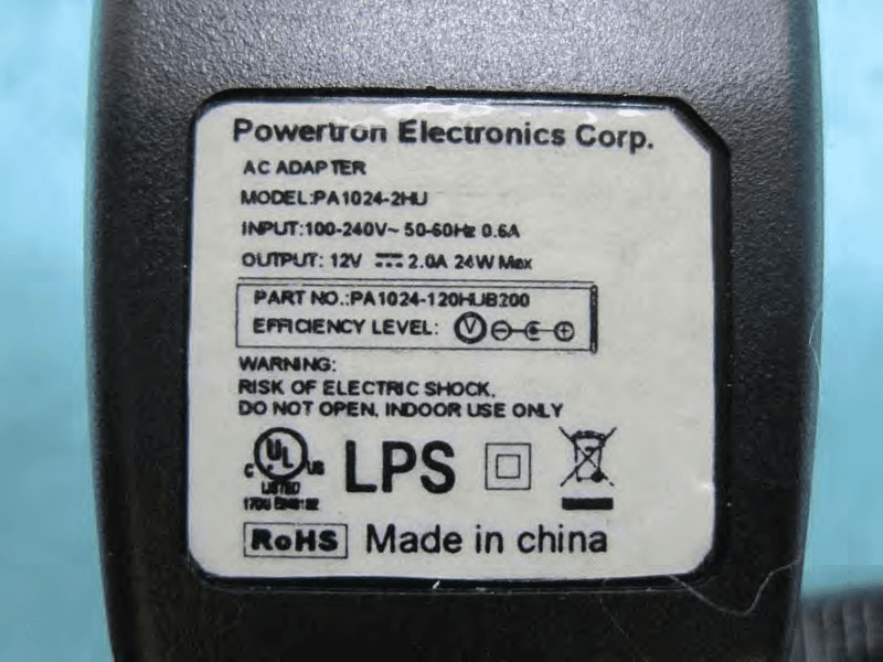
WBV-AP3X0
Aug 28, 2013Access Point
Equipment Class
NII - Unlicensed National Information Infrastructure TX