WCH99954226-7RCU DYNAMIC 2010
Maytronics Ltd.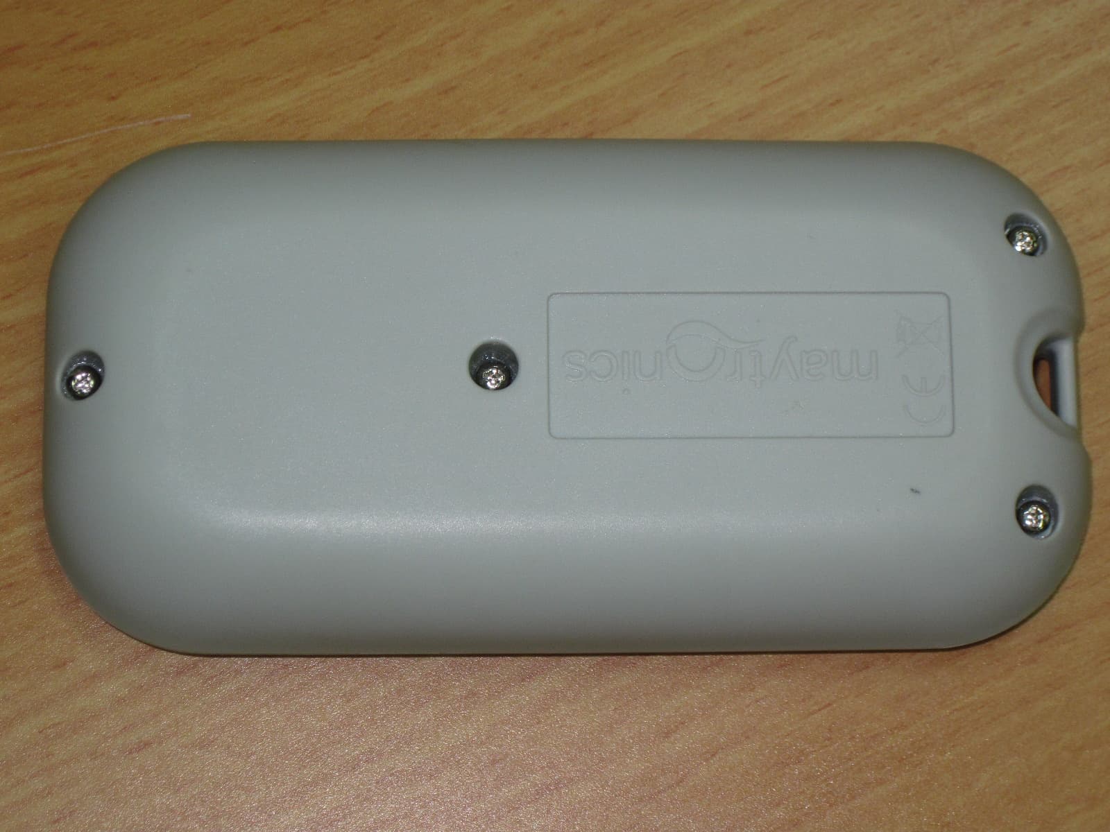
Click to zoom
Application Details
- Equipment Class
- DTS - Digital Transmission System
- Date of Grant
- Nov 09, 2010
- Application Purpose
- Original Equipment
- Date of Application
- Nov 08, 2010
- Equipment Note
- RCU DYNAMIC 2010
- Frequency Range
- 2433.00000000 - 2433.00000000
- Company
- Maytronics Ltd.
- Country
- Israel
Documents & Files
Document Text
Text extracted from the exhibit documents filed with the FCC. Open a document above to read the original.
Users Manual
Maytronics Remote Control Unit Télécommande, Maytronics Telecomando Maytronics Maytronics Unidad de Control Remoto Maytronics Fernbedienungseinheit Maytronics afstandsbediening Maytronics Unidade de Controlo Remoto Пульт Дистанционного Управления 1 - 4 9 - 12 13 - 16 17 - 20 21 - 24 25 - 28 29 - 32 8 32 1 Maytronics 2010 Remote Control Unit Ручное управление робота 1. Нажми кнопку вкл./выкл., один раз - ПДУ запустится в ручном режиме управления 2. Для ручного управления используй стрелки направления движения - см. справа Выход из ручного режима и установка автоматического режима 1. Для выхода из Ручного режима работы, необходимо нажать один раз на кнопку Выбора режима. 2. Цифровой экран загорится и в трѐх рядах функций высветятся значки вазовых установок 1. Для изменения параметров нажми на стрелки вверх/вниз Для выбора параметра нажми на стрелки вправо/влево 2.Для установки желаемой функции нажми кнопку ОК/установка Кнопка вкл./выкл. Стрелки направления движения Кнопка выбора режима Кнопка установки/ ОК Стрелки направления движения The 2010 Remote Control Unit (RCU) The RCU offers two operation modes - Automatic mode and Manual direction control mode. In Automatic mode, all cleaning parameters can be changed. In Manual direction mode, the Pool Cleaner direction can be controlled manually. The Control Panel of the Remote Control Unit ON/OFF button Manual/Automatic select button Direction Control Arrows Set/OK button Radio reception meter- If no black lines show, you should move closer to the power supply unit Cleaning mode icons Manual control indicator- When it flashes, you are in Manual Direction Control mode Battery level meter- When the icon flashes , change the batteries Cleaning Cycle icons Delay timer icons 2 31 Установка автоматического режима Для изменения установок автоматического режима Сначала нажми на кнопку выбора режима, затем выбери необходимые установки в соответствии с таблицей Датчик цикла чистки Определение цикла чистки. ПДУ позволяет выбрать один из следующих вариантов Быстрый Эффективный (Базовая установка) Экстра Supreme/Pulit 1.5 часа 2.5 часа для ежедневного использования 3.5 часа для частных бассейнов 2 часа 3 часа для ежедневного использования 4 часа для общественных бассейнов 4 часа 6 часа для ежедневного использования 8 часа Датчик задержки таймера Определение, когда робот начал работу Задержка позволяет мусору осесть на дно бассейна Немедленное начало (Базовая установка) Один час задержки Два часа задержки Датчик действий Позволяет выбрать один из следующих вариантов Стандарт Чистка дна и стен (Базовая установка) Усиленная чистка Усиленное всасывание и медленное движение Чистка дна и стыков Только дно Чистка дна и стыков Только стены Чистит только стены и линию воды Заметка: После 2 минут, если не нажата кнопка, ПДУ выключится, и робот будет продолжать работать в предыдущих настройках. Когда циклы работы, с выбранными опциями "Усильной чистки" и "Только стены", закончится, ПДУ вернѐтся к базисным установкам. FCC statement NOTE: This equipment has been tested and found to comply with the limits for a Class B digital device, pursuant to part 15 of the FCC Rules. These limits are designed to provide reasonable protection against harmful interference in a resi dential installation. This equipment generates, uses and can radiate radio frequency energy and, if not installed and used in accordance with the instructions, may cause harmful interference to radio communications. However, there is no guarantee that interference will not occur in a particular installation. If this equipment does cause harmful interference to radio or television reception, which can be determined by turning the equipment off and on, the user is encouraged to try to correct t he interference by one or more of the following measures: - Reorient or relocate the receiving antenna. - Increase the separation between the equipment and receiver. - Connect the equipment into an outlet on a circuit different from that to which the receiver is connected. - Consult the dealer or an experienced radio/TV technician for help. Changes or modifications to this equipment not expressly approved by the party responsible for compliance (Maytronics Ltd.) could void the user’s authority to operate the equipment. 30 3 Пульт Дистанционного Управления (ПДУ) 2010 ПДУ предоставляет два вида режима управления - Автоматический и ручной. В автоматическом режиме работы можно изменять все параметры чистки. В ручном режиме работы, движение робота управляется в ручную. Панель управления ПДУ Кнопка вкл/выкл. Выбор режима работы Автомат/ручной Направления Кнопка ОК/установки Значки режима чистки Датчик ручного управления- Если значок мигает, значит, установлен ручной режим Заряд батарей- Если значок мигает, необходимо заменить батареи Значки цикла чистки Значки задержки таймера Радиоприѐм- Если нет черных линий, необходимо приблизиться к блоку питания Setting the Automatic Mode To Change the Automatic Mode settings First press the Manual/Automatic select button, then set according to the following table: Cleaning cycle indicator This determines the cleaning cycle time. The RCU allows you to choose between the following options. Fast Efficient (Default setting) Extra Supreme/Pulit 1.5 hour cycle 2.5 hour cycle for everyday use 3.5 hour cycle Residential cleaners 2 hour cycle 3 hour cycle for everyday use 4 hour cycle Commercial cleaners 4 hour cycle 6 hour cycle for everyday use 8 hour cycle Delay Time indicator This determines when the pool cleaner starts to work. A delay allows the dirt to settle to the bottom of the pool. Immediate start (Default setting) One Hour delay Two Hours delay Cleaning action indicator Allowing you to choose from the following options. Standard Floor and wall cleaning. (Default setting) Ultra-clean Stronger suction and slower movement Floor and cove cleaning only. Floor only Cleans only the floor and coves. Walls Only Cleans walls and waterline only. Note: After 2 minutes, if no button is pr…
Text truncated - open the document above for the full version.
Operational Description
At turn on RCU RF module goes into idle state. Then in main loop it enters to transmit state and transmits 1 RF packet each 100ms. After transmit is done it enters into receive state by interrupt and waits for reply from PWS. If RCU RF module receives the correct RF packet from PWS within 100ms it is enters into idle state by interrupt. If not after 630ms timeout RCU RF module will go into idle state. In both cases RCU RF module enters again from to transmit state in the main loop.
Test Report
DATE: 14 September 2010 I.T.L. (PRODUCT TESTING) LTD. FCC Radio Test Report for Maytronics Ltd. Equipment under test: Remote Control For Dolphin Supreme M5 RCU Dynamic 2010; RCU Basic 2010* * See customer’s declaration on page 6. Written by: _____________________________ D. Shidlowsky, Documentation Approved by: _____________________________ A. Sharabi, Test Engineer Approved by: _____________________________ I. Raz, EMC Laboratory Manager This report must not be reproduced, except in full, without the written permission of I.T.L. (Product Testing) Ltd. This report relates only to items tested. Test Report E95250.00 Maytronics Ltd. Page 1 of 44 FCC ACC M Ver 1.1 05Mayl 2000 Test Report E95250.00 Maytronics Ltd. Page 2 of 44 FCC ACC M Ver 1.1 05Mayl 2000 Measurement/Technical Report for Maytronics Ltd. Remote Control For Dolphin Supreme M5 RCU Dynamic 2010 FCC ID: WCH99954226-7 This report concerns: Original Grant: X Class I Change: Class II Change: Equipment type: Digital Transmission System Limits used: 47CFR15 Section 15.247 Measurement procedure used is ANSI C63.4-2003. Application for Certification Applicant for this device: prepared by: (different from "prepared by") Ishaishou Raz Yair Hadari ITL (Product Testing) Ltd. Maytronics Ltd. Kfar Bin Nun Kibbutz Yizrael D.N. Shimshon 99780 D.N. Emek Yizrael 19350 Israel Israel e-mail [email protected] Tel: +972- 4 - 659 - 8111 Fax: +972- 4 - 652 - 2485 e-mail: [email protected] Test Report E95250.00 Maytronics Ltd. Page 3 of 44 FCC ACC M Ver 1.1 05Mayl 2000 TABLE OF CONTENTS 1. GENERAL INFORMATION ------------------------------------------------------------------------------- 5 1.1 Administrative Information ................................................................................. 5 1.2 List of Accreditations ......................................................................................... 7 1.3 Product Description ........................................................................................... 8 1.4 Test Methodology .............................................................................................. 8 1.5 Test Facility ....................................................................................................... 8 1.6 Measurement Uncertainty ................................................................................. 8 2. SYSTEM TEST CONFIGURATION --------------------------------------------------------------------- 9 2.1 Justification ........................................................................................................ 9 2.2 EUT Exercise Software ..................................................................................... 9 2.3 Special Accessories .......................................................................................... 9 2.4 Equipment Modifications ................................................................................... 9 2.5 Configuration of Tested System ........................................................................ 9 3. TEST SETUP PHOTOGRAPHS ------------------------------------------------------------------------10 4. 6DB MINIMUM BANDWIDTH ---------------------------------------------------------------------------11 4.1 Test Specification ............................................................................................ 11 4.2 Test procedure ................................................................................................ 11 4.3 Test Results .................................................................................................... 12 4.4 Test Equipment Used. ..................................................................................... 13 5. RADIATED POWER OUTPUT --------------------------------------------------------------------------14 5.1 Test Specification ............................................................................................ 14 5.2 Test procedure ................................................................................................ 14 5.3 Results Calculation .......................................................................................... 15 5.4 Test Equipment Used. ..................................................................................... 16 6. BAND EDGE ------------------------------------------------------------------------------------------------17 6.1 Test procedure ................................................................................................ 17 6.2 Results table .................................................................................................... 19 6.3 Test Equipment Used. ..................................................................................... 20 7. RADIATED EMISSION, 9 KHZ – 30 MHZ -----------------------------------------------------------21 7.1 Test Specification ............................................................................................ 21 7.2 Test Procedure ................................................................................................ 21 7.3 Measured Data ................................................................................................ 21 7.4 Test Instrumentation Used, Radiated Measurements .................................... 22 7.5 Field Strength Calculation ............................................................................... 22 8. SPURIOUS RADIATED EMISSION 30 – 25000 MHZ --------------------------------------------23 8.1 Test Specification ............................................................................................ 23 8.2 Test Procedure ................................................................................................ 23 8.3 Test Data ......................................................................................................... 24 8.4 Test Instrumentation Used, Radiated Measurements .................................... 27 8.5 Field Strength Calculation 30 –…
Text truncated - open the document above for the full version.
Contact Information
Applicant
Yair Hadari(Manager of hardware and software development)
Test Firm
Israel Testing LaboratoriesIIan Cohen
Technical Specifications
| # | Rule Parts | Frequency Range | Power Output |
|---|---|---|---|
| 1 | 15C | 2.43 GHz - 2.43 GHz | 1.00 mW |
Other Applications from Maytronics Ltd.
WCHSKIM2
Feb 10, 2026Pool surface cleaner
Equipment Class
DTS - Digital Transmission System
WCHWAVEBTFSK
Oct 30, 2023WAVE 140 POWER SUPPLY
Equipment Class
DTS - Digital Transmission System
WCH9995412
Jul 02, 2023Remote Control Unit for Robotic Pool Cleaner
Equipment Class
DSC - Part 15 Security/Remote Control Transmitter
WCHLIBERTY
Apr 12, 2023Wireless Robotic Pool Cleaner with Inductive Charger
Equipment Class
DTS - Digital Transmission System
WCH99956035
Mar 05, 2015Bluetooth Communication Transceiver Module
Equipment Class
DTS - Digital Transmission System