WCH99956035Bluetooth Communication Transceiver Module
Maytronics Ltd.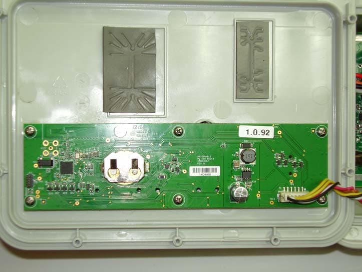
Click to zoom
Application Details
- Equipment Class
- DTS - Digital Transmission System
- Date of Grant
- Mar 05, 2015
- Application Purpose
- Original Equipment
- Date of Application
- Mar 05, 2015
- Equipment Note
- Bluetooth Communication Transceiver Module
- Frequency Range
- 2402.00000000 - 2480.00000000
- Company
- Maytronics Ltd.
- Country
- Israel
Documents & Files
Document Text
Text extracted from the exhibit documents filed with the FCC. Open a document above to read the original.
Users Manual
User’s instructions to use the Bluetooth® communication in order to operate MyDolphin™ application features. “Contains FCC ID: WCH99956035“. Connect the robot’s power-supply to the mains. Connect your Smartphone to the internet, and download Maytronics MyDolphin™ application from Apple or Android App Store, according to the relevant Smartphone. “User authentication procedure” : Please enter the application, click on the robot that appears on the Smartphone screen (serial number) Login using your e-mail address and choose a password. Proceed to Bluetooth® pairing on your Smartphone. The Smartphone Identifies the robot and initiates a pairing sequence. Now the strong signal transmitter communicates remotely with the power supply via Bluetooth®. Main screen window shows operational status and information, including remaining cycle time and selected cleaning mode. Buttons on lower half of the screen represent the available operational modes: cleaning mode, manual drive, cycle time, weekly timer, info/links, and delay mode. Choose the mode you want to operate. Cleaning mode: You can choose between different operation options such as: Floor Only, Regular mode or others. Manual Mode: To manually clean specific areas of your pool. You can also switch to Tilt mode for a realistic experience. Cleaning Cycle Time: You can choose between different cleaning cycle times. Weekly Timer: Use this mode to choose the days and hours during the week that the robot will operate. Delay Mode: Use this mode to delay the start of the robot operation. You can exit the application by touching the X on the Smartphone upper-left screen and choosing OK to close “MyDolpin™”
Cover Letter(s)
LIMITED MODULAR APPROVAL LETTER FCC ID: WCH99956035 Item Requirements EUT 1 The modular transmitter must have its own RF shielding DOESN'T HAVE ITS OWN RF SHIELDING 2 The modular transmitter must have buffered modulation/data inputs. MODULE TRANSMITTER HAS BTE TRANSMITION PROTOCOL 3 The modular transmitter must have its own power supply regulation. GETS POWER INTERNALLY FROM ITS POWER SUPPLY. USES BACK‐ UP BATTERY FOR DATA 4 The modular transmitter must comply with the antenna and transmission system requirements of sections 15.203, 15.204(b) and 15.204(c) COMPLIES, ANTENNA IS PRINTED ON THE PCB 5 The modular transmitter must be tested in a stand‐alone configuration, i.e., the module must not be inside another device during testing. This is intended to demonstrate that the module is capable of complying with Part 15 emission limits regardless of the device into which it is eventually installed. THE MODULAR TRANSMITTER HAS BEEN TESTED INSIDE THE AUXILIARY DEVICE, THEREFORE WE ASK FOR LIMITED APPROVAL OF THE MODULE 6 The modular transmitter must be labeled with its own FCC ID number, and, if the FCC ID is not visible when the module is installed inside another device, then the outside of the device into which the module is installed must also display a label referring to the enclosed module. This exterior label can use wording such as the following: "Contains Transmitter Module FCC ID: XYZMODEL1" or "Contains FCC ID: XYZMODEL1." Any similar wording that expresses the same meaning may be used. The Grantee may either provide such a label, an example of which must be THE MODULAR TRANSMITTER IS LABELED WITH FCC ID AND AS IT IS NOT VISIBLE TO THE USER, THERE IS AN EXTERIOR LABEL: 'CONTAINS FCC ID: WCH99956035" included in the application for equipment authorization, or, must provide adequate instructions along with the module which explain this requirement. In the latter case, a copy of these instructions must be included in the application for equipment authorization 7 The modular transmitter must comply with any specific rule or operating requirements applicable to the transmitter and the manufacturer must provide adequate instructions along with the module to explain any such requirements. REFER TO TEST REPORT (to be inputted by SII) DEVICE COMPLIES TO PART 15.247 8 The modular transmitter must comply with any applicable RF exposure requirements. COMPLIES Yair Hadari R&D manager Maytronics Ltd. Signature: ___ ___
External Photos
1 External photos FCC ID: WCH99956035 The Transceiver Module position into the auxiliary equipment The Transceiver Module position into the auxiliary equipment. RF board only 2 The auxiliary equipment external front view. The auxiliary equipment external rear view.
ID Label/Location Info
FCC PCA LABLE Size: 5x26 mm Material: Kapton Polymide Printed in Black Font size 6 pt. FCC ID: WCH99956035
Internal Photos
Internal photos FCC ID: WCH99956035
Operational Description
Theory of Operation/Technical Description for Transceiver Module FCC ID: WCH99956035 The EUT (Equipment Under Test) is the Transceiver Module inside the power supply for a pool cleaning robot. The module in the power supply can turn on the robot automatically using a scheduled timer. 4 pushbuttons and an icon based LED display are used for the MMI (Man Machine Interface). The transceiver module is based on a single chip CC2541 (designationU4) from TI that connects to a Smartphone using BLE (Bluetooth Low Energy V4.0) communication for sending and receiving commands to control the robot. The RF output transmitting power of the transceiver (U4 – CC2541) is 0dBm and the gain of the built‐in non detachable inverted F antenna (printed on the PCB and non‐detachable) is 0dB. The transceiver uses GFSK modulation on 40 channels in adaptive frequency hopping starting from 2402MHz up to 2480MHz with 1.95MHz spacing following the Bluetooth V4.0 compliant protocol. An internal backup battery is used for the Real Time Clock to operate while the power supply is disconnected from the outlet. The CC2541 IC (the BLE transceiver chip) is using a Crystal oscillator of 32MHz providing the main Clock and a 32.768 KHz for a real time clock feature.
Test Report
Test Report No. 9412320094 For Maytronics Ltd Equipment Under Test: Transceiver Module Model: M2 PWS COM FCC ID: WCH99956035 From The Standards Institution Of Israel Industry Division Electronics & Telematics Laboratory EMC Branch ACLASS Accreditation Services Certificate Number: AT-1359 Test report No: 9412320094 Page 2 of 33 Pages Title: Transceiver Module Model : M2 PWS COM Table of Contents 1. Applicant information ............................................................................................................... 3 2. Test performance ...................................................................................................................... 3 3. Summary of test: ....................................................................................................................... 5 4. Equipment under test description. .......................................................................................... 6 4.1 General description .................................................................................................................. 6 4.2 Environmental evaluation and exposure limit according to FCC CFR 47 part 1, §§1.1307, 1.310. .......................................................................................................................................... 6 4.3 Test configuration ..................................................................................................................... 7 5. Test results ................................................................................................................................ 8 5.1 Transmitter characteristics ..................................................................................................... 8 5.1.1 Transmitter 6 dB occupied bandwidth. ........................................................................... 8 5.1.2 Maximum peak conducted output power test. ............................................................. 10 5.1.3 Power spectral density test ............................................................................................ 12 5.1.4 Radiated emissions according to §§ 15.247(d), 15.205(a) ........................................... 13 5.2 Radiated emissions test according to § 15.209 ................................................................... 19 5.3 Conducted emissions test according to § 15.207. ............................................................... 22 APPENDIX A Test equipment used. .......................................................................................... 25 APPENDIX B Photo of the test setups. ..................................................................................... 30 APPENDIX C Abbreviations and acronyms. ............................................................................ 33 Test report No: 9412320094 Page 3 of 33 Pages Title: Transceiver Module Model : M2 PWS COM 1. Applicant information Applicant: Maytronics Ltd Address: Kibbutz Yizre'el, 19350 Israel Sample for test selected by: The customer The date of tests: 11, 17 December 2014, 19 February 2015 Equipment under test information Description of Equipment Under Test (EUT ): Transceiver Module Model: M2 PWS COM Serial Number: 14/24900 Hardware version: M2 Com Board rev.3 Software version: Rev. 3.2 Manufactured by: Maytronics Ltd. 2. Test performance Location: SII EMC Section Purpose of test: Apparatus compliance verification in accordance with emission requirements Test specifications: 47CFR part 15.247, 15.205 15.207. 15.209 and part 1 §1.1310 This Test Report contains 33 pages and may be used only in full. This Test Report applies only to the specimen tested and may not be applied to other specimens of the same product. Test report No: 9412320094 Page 4 of 33 Pages Title: Transceiver Module Model : M2 PWS COM Normative References. FCC 47 CFR Part 15, Subpart C, 2014 Radio Frequency Devices Subpart C – Intentional Radiators ANSI C63.4: 2009 American National Standard for Method of Measurements of Radio-Noise Emissions from Low- Voltage Electrical and Electronic Equipment in the Range of 9 kHz to 40 GHz ANSI C63.10: 2009 American National Standard for Testing of Unlicensed Wireless Devices. FCC OET KDB 558074, June 2014 Guidance for Performing Compliance Measurements on Digital Transmission Systems (DTS) Operating Under §15.247 Test report No: 9412320094 Page 5 of 33 Pages Title: Transceiver Module Model : M2 PWS COM 3. Summary of test: The EUT was found to be in compliance with requirements of: 47CFR Part 15, §§ 15.247, 15.205 and 15.209 . Transmitter characteristics Subclasses Minimum 6 dB bandwidth 15.247(a)(2) Maximum output power 15.247(b)(3) Peak power spectral density 15.247(e) Out of band spurious emissions radiated 15.205, 15.247(d) Conducted emissions on AC power line 15.207 Unwanted radiated emissions below 1 GHz 15.209 Electronics and Telematics Laboratory February 2015 Name: Eng. Yuri Rozenberg Position: Head of EMC Branch Name: Michael Feldman Measurement uncertainty. The test equipment has been calibrated according to its recommended procedures and is within the manufacturer's published limit of error. The laboratory calibrates its standards by a third party (traceable to NIST, USA) on a regular basis according to equipment manufacturer requirements. In the following table the uncertainty calculation is given. Type of disturbance Test description Calculated uncertainty U LAB Radiated emissions electric field strength in a SAR at 3 m distance 30 MHz – 1.0 GHz electric field strength in a FAR at 3 m distance 1.0 GHz – 18 GHz Substitution measurements in a FAR at 3 m distance 1.0 GHz – 18 GHz 4.32 dB 4.47 dB 3.41 dB Test report No: 9412320094 Page 6 of 33 Pages Title: Transceiver Module Model : M2 PWS COM 4. Equipment under test description. *The customer provided description. 4.1 General description The EUT is a Transceiver module that communicates through BLE protocol to Smartphones that have installed the My…
Text truncated - open the document above for the full version.
Test Setup Photos
Test set up photos Photo 1.. Radiated emissions test setup with Loop antenna. Photo 2. Radiated emissions test setup with Biconilog antenna. Photo 3. Radiated emissions test setup with Horn antenna. Photo 4. Radiated emissions test at 1m distance. Photo 5. Radiated emissions test setup front view. Photo 6. Radiated emissions test setup rear view.
Contact Information
Applicant
Yair Hadari(Manager of hardware and software development)
Test Firm
The Standards Institution of IsraelYuri Rozenberg
Technical Specifications
| # | Rule Parts | Frequency Range | Power Output |
|---|---|---|---|
| 1 | 15C | 2.40 GHz - 2.48 GHz | 1.00 mW |
Other Applications from Maytronics Ltd.
WCHSKIM2
Feb 10, 2026Pool surface cleaner
Equipment Class
DTS - Digital Transmission System
WCHWAVEBTFSK
Oct 30, 2023WAVE 140 POWER SUPPLY
Equipment Class
DTS - Digital Transmission System
WCH9995412
Jul 02, 2023Remote Control Unit for Robotic Pool Cleaner
Equipment Class
DSC - Part 15 Security/Remote Control Transmitter
WCHLIBERTY
Apr 12, 2023Wireless Robotic Pool Cleaner with Inductive Charger
Equipment Class
DTS - Digital Transmission System
WCH99954226-7
Nov 09, 2010RCU DYNAMIC 2010
Equipment Class
DTS - Digital Transmission System