WCHSKIM2Pool surface cleaner
Maytronics Ltd.Application Details
- Equipment Class
- DTS - Digital Transmission System
- Date of Grant
- Feb 10, 2026
- Application Purpose
- Original Equipment
- Equipment Note
- Pool surface cleaner
- Frequency Range
- 2402.00000000 - 2480.00000000
- Company
- Maytronics Ltd.
- Country
- Israel
Documents & Files
Document Text
Text extracted from the exhibit documents filed with the FCC. Open a document above to read the original.
Attestation Statements
Covered list attestation FCC application letter Kiwa Page 1 of 2 RF_755_03 06-06-2024 Certification Application Attestation Statements Maytronics Ltd. <0017809245> < Kibbutz Yizre’el, > <1935000> < Israel > Subject: FCC ID: < WCHSKIM2> To Whom It May Concern: Statement for 47 CFR section 2.911(d)(5)(i) [ Maytronics Ltd.] certifies that as of the date of the application the equipment for which authorization is sought is not “covered” equipment 1 prohibited from receiving an equipment authorization pursuant to section 2.903 of the FCC rules. If the equipment for which the applicant seeks authorization is produced by any of the entities identified on the current Covered List, including affiliates or subsidiaries of the named companies, the applicant must include an explanation on why the equipment is not “covered” equipment. Additional Explanation: <N/A> Statement for 47 CFR section 2.911(d)(5)(ii) [ Maytronics Ltd.] certifies that, as of the date of the filing of this application, the applicant - is / - is not (3) identified on the Covered List as an entity producing “covered” equipment. Date: 06-Jan-26 City: Kibbutz Yizre’el Name (2) : Yair Hadari Function: Manager of hardware and software development Telephone number: +972 4659 8359 Email address: [email protected] 1 - The Commission’s Covered List is published by the Public Safety and Homeland Security Bureau and posted on the Commission’s website. This Covered List, which is periodically updated, identifies particular equipment, produced by particular entities, that constitutes “covered” equipment. https://www.fcc.gov/supplychain/coveredlist . (2): For FCC it must be the Grantee Code “owner” or the authorized agent. (3): double click on the appropriate box and select ‘’checked” then “OK” Covered list attestation FCC application letter Kiwa Page 2 of 2 RF_755_03 06-06-2024 Signature: Revision Record Sheet: Revision Section number Page number Date Remark(s) issued by 01 07-02-2023 1 st version RvM 02 1 15-02-2023 Changed Applicant to Company and added “Subject: FCC ID: “ RvdM 03 1 06-06-2024 FRN added at certification application and included [Insert Company Name Here] for the statements RvdM Issued/modified by : Richard van de Meer Function : Certification assessor Revision : 03 Date : 06-06-2024 Verified by : Willem Jan Jong Function : Team Lead Date : 06-06-2024 Released by : Axel Gase Function : Manager Quality Assurance Date of release: : 06-06-2024
Attestation Statements
Federal Communications Commission Authorization and Evaluation Division 7435 Oakland Mills Road Columbia, MD 21046 USA Date: 05/02/2026 Ref: Attestation Statement Part 2.911(d)(7) Filing FCC ID: WCHSKIM2 Maytronics Ltd.certifies that, as of the dates of this application, Americas Compliance Consulting LLC dba iCertifi is our designated U.S. agent for service of process for the above referenced FCC ID. Manufacturer accepts to maintain an agent for no less than two year after the grantee has terminated all marketing and importation or the conclusion of any commission-related proceeding involving the equipment. iCertifi accepts, as of the date of the filing of the application, the obligation of the designated U.S. agent for service process for the above referenced FCC ID. Designated U.S. Agent Information: Name: Americas Compliance Consulting LLC dba iCertifi FCC FRN: 0033399411 Address: 5809 US-2, Suite B, Albeni Plaza Priest River, Idaho 83856, United States Contact Person: Paul Preston Tel: +1 (866) 885-4575 Email: [email protected] Sincerely, Maytronics Ltd. Americas Compliance Consulting LLC dba iCertifi FRN: 0017809245 FRN: 0033399411 Yair Hadari Paul Preston [email protected] [email protected] +972 4659 8359+1 (866) 885-4575 Signature:Signature:
Cover Letter(s)
RF_160_06 Declaration of Authorisation Date of issue 13-08-2025 Declaration of Authorization We Name: < Maytronics Ltd.> Address: ... Kibbutz Yizreel ............ ................................................. City: ... Kibbutz Yizreel 1935000... ........................................ Country: ...... Israel ................................................. Declare that: Name Representative of agent: Peysahov Sheynin Svetlana (1) Agent Company name: Hermon Laboratories Ltd.. Address: Harakevet Industrial Zone.. City: ... Binyamina 3055001.. Country ... Israel .... is authorized to apply for Certification of the following product(s): Product description: ...... Pool surface cleaner ................... Type designation: ......... SKIMMI2......................... Trademark: ......... Maytronics Ltd ............................. Validity/ expiry date 06-Jan-2027 on our behalf. Date: ......06-Jan-2026... ........ City: ... Kibbutz Yizreel ........... Name: ... Yair Hadari ................. (2) Function: ...... CTO .......... Signature: ............................... Notes: (1): Required for FCC application (2): For FCC it must be the Grantee Code “owner” or the authorized agent. Revision Record Sheet: Revision Section number Page number Date Remark(s) issued by 05 1 02-01-2023 History sheet added AG 06 all 13-08-2025 Kiwa logo change AG Issued/modified by : Axel Gase Function : Manager Quality Assurance Revision : 06 Date : 13-08-2025 Verified by : Willem Jan Jong Function : Team Lead Date : 13-08-2025 Released by : Axel Gase Function : Manager Quality Assurance Date of release: : 13-08-2025
Cover Letter(s)
FCC, Request for non-disclosure Date: 18-08-2025 RF_501, Issue 12 Page 1 of 2 Company Name: Maytronics Ltd. Address : Kibbutz Yizreel City: Kibbutz Yizreel 19350 Country: Israel To: Kiwa Netherlands B.V., Dept. FCC TCB Wilmersdorf 50 7327 AC Apeldoorn The Netherlands Subject: Request for confidentiality FCC ID: WCHSKIM2 Reference number: 56775 Dear FCC TCB, 1. Long-Term Confidentiality Pursuant to 47 CFR Section 0.459(a) & (b), we hereby requests non-disclosure and confidential treatment of the following materials submitted in support of FCC certification application: Bill(s) of Material Block Diagrams Operational Description Schematic Diagrams Tune-up Procedure Above materials contain secrets, proprietary and technical information, which would customarily be guarded from competitors under 47 CFR, section 0.457(d)(2). Disclosure or publication or any portion of this company confidential material to other parties could cause substantial competitive harm and provide unjustified benefits for competitors. 2. Short-Term Confidentiality (STC) Pursuant to Public Notice DA 04-1705 of the Commission’s policy, in order to comply with the marketing regulations in 47 CFR §2.803 and the importation rules in 47 CFR §2.1204, a pplicant hereby requests Short-Term Confidential treatment of the following materials (See notes below): Internal Photos User’s Manual Test Set-up Photos External Photos Justification: in order to avoid exposed of the technology to the competitors Date: 06-Jan-2026 Name and signature of applicant: Yair Hadari Notes: 1) A document or type of document can only have ONE type of confidentiality! 2) Short-Term confidentiality is in principle for 45 days from date of grant; it can be extended max 3 times (total time 180 days max.)! The planned date should state in the RF731 application form. 3) FCC must be informed when marketing begins earlier. 4) Release takes place automatically thus extension must be requested in time. Telefication does not remind you of this! 5) Request for extension or for release must be received by Kiwa NL B.V. at least 7 days before date of actual marketing or before expiration of the STC period FCC, Request for non-disclosure Date: 18-08-2025 RF_501, Issue 12 Page 2 of 2 Revision Record Sheet: Revision Section number Page number Date Remark(s) issued by 10 1 02-01-2023 History sheet added AG 11 1 & 2 23-06-2023 Corrected date and page# WJJ 12 all 18-08-2025 Kiwa logo change AG Issued/modified by : Axel Gase Function : Manager Quality Assurance Revision : 12 Date : 18-08-2025 Verified by : Willem Jan Jong Function : Team Lead Date : 18-08-2025 Released by : Axel Gase Function : Manager Quality Assurance Date of release: : 18-08-2025
ID Label/Location Info
Page 1 of 1 LABEL The label is affixed on the side panel of the power supply as shown below. The label material is PVC with a permanent adhesive.
RF Exposure Info
FCC ID: WCHSKIM2 RF exposure evaluation The Pool surface cleaner includes a BLE transmitter. The minimum separation distance is assured by the typical device usage is 0.1 m (10cm). When the minimum separation distance will be more than the calculated value prescribed for the frequency (2480 MHz) then the exemption in Table 1 §1.1307(b)(3)(i)(C) of MPE based exemption criteria will be apply. The minimum separation distance for 2480 MHz frequency will be calculate as following: R=λ/2π=0.0192m Where λ is the free-space operating wavelength in meters and R is a minimum separation distance (in meters). MPE based exemption criteria according to Table 1 to §1.1307(b)(3)(i)(C) The MPE based exemption threshold at frequency 2480 MHz and test separation distance 0.1m (10cm) will be: 19.2x0.1 2 =0.192W = 192mW Maximum BLE measured transmitter power obtained from test report MAYRAD_FCC.56775_Rev1: Pout ERP Maximum antenna gain, dBd Pout conducted dBm mW dBm mW 3.59 2.28 1.95 1.64 1.46 The MPE exemption condition in terms of ERP at 2480 MHz frequency and 0.1m separation distance relates is 192mW threshold, so BLE is exempt and no evaluation is required. The BLE transmitter exempt from MPE evaluation as per section 2.1.4 of KDB Publication 447498 D01 v07. Based on the above the product can be considered complying with the RF exposure limitations.
Test Report
Introduction This application note is dedicated to the STM32WB and STM32WB0 series microcontrollers. One of the main reasons to use a printed circuit board (PCB) antenna is the reduced overall cost of the radio module. Well- designed and implemented PCB-printed antennae have a similar performance to the SMD (surface-mounted device) ceramic equivalence. In general, the footprint for a ceramic SMD antenna is smaller than that for a PCB-printed variant. For a PCB-printed antenna solution, the increased size of the PCB in relation to the space required for the antenna means that the radio module is larger, increasing the cost of the PCB. However, the PCB solution is generally cheaper than an SMD ceramic antenna. The demonstration and development boards for the STM32WB and STM32WB0 series implement PCB-printed antennae based on this application note. Guidelines for meander design using low-cost PCB antennae with 2.4 GHz radio for STM32WB/WB0 MCUs AN5129 Application note AN5129 - Rev 5 - April 2024 For further information contact your local STMicroelectronics sales office. www.st.com 1 General information This document applies to STM32WB and STM32WB0 series Arm ® based devices. Note:Arm is a registered trademark of Arm Limited (or its subsidiaries) in the US and/or elsewhere. AN5129 General information AN5129 - Rev 5 page 2/22 2 Coordinate system For the purpose of this document, the spherical coordinate system illustrated in the figure below is used. Figure 1. Spherical coordinate system The PCB module is orientated vertically (plane X-Z) and located in proximity to the origin of the coordinate system. The azimuth angle radiates from the X-axis towards the Y-axis and the elevation angle radiates from the Z-axis towards the horizontal X-Y plane. Sometimes, as with geographical and navigational systems, the X-axis is called the "Nord-axis", the Yaxis is called the "East-axis" and the Z-axis is called the "Zenith-axis". AN5129 Coordinate system AN5129 - Rev 5 page 3/22 3 Layout specification The PCB antennas, including the electrical parameters of PCB materials used, are layout sensitive. It is recommended to use a layout as close as possible to the one shown in the figure below. Figure 2. PCB antenna dimensions (in mm) The electrical parameters and performance of the PCB antenna are also determined by the substrate used, in particular the thickness of the core and dielectric constants. AN5129 Layout specification AN5129 - Rev 5 page 4/22 The figure below illustrates a typical cross-section of the substrate in a PCB-antennae area. Figure 3. PCB cross section at antennae area A substrate with the parameters as defined in the table below is recommended. Table 1. Recommended substrate specification Layer Dimensions Dielectric constant Ɛ R LabelValue (mil)Value (μm) Solder mask, top S10.717.78 4.4 Copper traceT1.640.64- CoreC28711.24.4 Solder mask, bottomS20.717.784.4 AN5129 Layout specification AN5129 - Rev 5 page 5/22 4 Impedance matching Meander-like PCB antennae can be tuned to the required 50‑Ω impedance by matching the impedance circuitry with the π topology. In Figure 2, the impedance matching area is marked with a dashed line. Under nominal conditions, this antenna exhibits and impedance very close to the required nominal impedance (50 Ω). To check the performance of this design, a sample antenna was manufactured (according to the specifications covered by this document). The figure below shows this antenna. Figure 4. Part of 802.15.4 and BLE PCB with meander-like antenna (scale approximately 4:1) Assuming that the manufactured sample exhibits the expected performance (no impedance matching necessary), the impedance matching circuitry is bypassed by two 100‑pF capacitors connected in series, as shown in the figure below. Figure 5. Bypassing impedance matching circuitry - Direct RF connection All electrical parameters of the meander-like antenna have been measured at connection to the band-pass filter (BPF) with the frequency span covering frequencies from 2.4 GHz to 2.5 GHz. AN5129 Impedance matching AN5129 - Rev 5 page 6/22 The figure below shows the complex impedance of the antenna in a Smith chart. Figure 6. Complex impedance of the meander-like antenna (Smith chart) The figure below shows the magnitude of the S11 parameter (in log scale). Figure 7. S11 parameter in logarithmic scale (Cartesian plot) AN5129 Impedance matching AN5129 - Rev 5 page 7/22 The figure below shows the standing wave ratio (SWR). Figure 8. Antenna standing wave ratio (SWR) The following changes affect the radiation impedance of the PCB antenna: •Board size variation •Metal shielding •Use of plastic cover •Presence of other components in proximity of the antenna The best performance impedance matching circuitry compensates these effects so that, for operating frequencies, the optimum 50‑Ω impedance is achieved. AN5129 Impedance matching AN5129 - Rev 5 page 8/22 5 Radiation pattern, 3-D visualization A three-dimensional (3-D) visualization of the radiation pattern (magnitude of the electrical far field |E|) is done for the center ISM band frequency 2.44175 GHz. Figure 9. 3-D radiation pattern overview Figure 10. Radiation pattern on X-Z plane AN5129 Radiation pattern, 3-D visualization AN5129 - Rev 5 page 9/22 6 Radiation pattern, 2-D visualization In this section, all radiation patterns are related to the magnitude of the electrical far field |E|, which is normalized and shown in the logarithmic scale (in dB). This means that the maximum global radiation pattern (maximum magnitude of the electrical far-field |E|) is represented by a 0 dB level. To show the antenna radiation patterns in detail, three two-dimensional (2-D) major cuts are presented. Consider the orientation of the module in the spherical coordinate system as shown in Figure 1. A three-dimensional (3-D) far field radiation pattern is visualized as three 2-D cuts through a 3-D pattern. The following major planes are used for these cuts (see Figure 11): •…
Text truncated - open the document above for the full version.
Test Report
Hermon Laboratories Ltd. 66 HaTachana str., P.O. Box 23, Binyamina 3055001, Israel Tel. +972 4628 8001 Fax. +972 4628 8277 E-mail: [email protected] Page 1 of 67 Report ID: MAYRAD_FCC.56775_Rev1.docx Date of Issue: 4-Feb-26 ELECTRICAL TESTING 0839.01 TEST REPORT ACCORDING TO: FCC 47CFR part 15 subpart C §15.247 (DTS), RSS-247 Issue 4:2025, RSS-Gen Issue 5 FOR: Maytronics Ltd. Pool surface cleaner Model: SKIMMI2 FCC ID: WCHSKIM2 IC: 29982-SKIM2 This report is in conformity with ISO/ IEC 17025. The "A2LA Accredited" symbol endorsement applies only to the tests and calibrations that are listed in the scope of Hermon Laboratories accreditation. The test results relate only to the items tested. This test report shall not be reproduced in any form except in full with the written approval of Hermon Laboratories Ltd. Report ID: MAYRAD_FCC.56775_Rev1.docx Date of Issue: 4-Feb-26 Page 2 of 67 Table of contents 1 Applicant information ..................................................................................................................................................... 3 2 Equipment under test attributes .................................................................................................................................... 3 3 Manufacturer information .............................................................................................................................................. 3 4 Test details .................................................................................................................................................................... 3 5 Tests summary .............................................................................................................................................................. 4 6 EUT description ............................................................................................................................................................. 5 6.1 General information ....................................................................................................................................................... 5 6.2 Changes made in EUT .................................................................................................................................................. 5 6.3 Test configuration .......................................................................................................................................................... 5 6.4 Transmitter characteristics ............................................................................................................................................ 6 7 Transmitter tests according to 47CFR part 15 subpart C and RSS-247 requirements .................................................. 7 7.1 Minimum 6 dB and 99% bandwidth ............................................................................................................................... 7 7.2 Peak output power ...................................................................................................................................................... 11 7.3 Field strength of spurious emissions ........................................................................................................................... 18 7.4 Band edge radiated emissions .................................................................................................................................... 42 7.5 Peak spectral power density ....................................................................................................................................... 47 7.6 Conducted emissions .................................................................................................................................................. 54 7.7 Antenna requirements ................................................................................................................................................. 59 8 APPENDIX A Test equipment and ancillaries used for tests ....................................................................................... 60 9 APPENDIX B Test equipment correction factors ......................................................................................................... 61 10 APPENDIX C Measurement uncertainties .................................................................................................................. 65 11 APPENDIX D Test laboratory description ................................................................................................................... 66 12 APPENDIX E Specification references........................................................................................................................ 66 13 APPENDIX F Abbreviations and acronyms ................................................................................................................. 67 Report ID: MAYRAD_FCC.56775_Rev1.docx Date of Issue: 4-Feb-26 Page 3 of 67 1 Applicant information Client name: Maytronics Ltd. Address: Kibbutz Yizre'el, 1935000, Israel Telephone: +972 4-6598113 Fax: +972 4-6522485 E-mail: [email protected] Contact name: Mr. Eugene Plotnichenko 2 Equipment under test attributes Product name: Pool surface cleaner Product type: Transceiver Model(s): SKIMMI2 Serial number: prototype Hardware version: 2 Software release: 20.49 Receipt date 19-May-25 3 Manufacturer information Manufacturer name: Maytronics Ltd. Address: Kibbutz Yizre'el, 1935000, Israel Telephone: +972 4-6598113 Fax: +972 4-6522485 E-Mail: [email protected] Contact name: Mr. Eugene Plotnichenko 4 Test details Project ID: 56775 Location: Hermon Laboratories Ltd. P.O. Box 23, Binyamina 3055001, Israel Test started: 22-May-25 Test completed: 18-Jun-25 Test specification(s): FCC 47CFR part 15 subpart C §15.247 (DTS), RSS-247 Issue 4:2025, RSS-Gen Issue 5 Report ID: MAYRAD_FCC.56775_Rev1.docx Date of Issue…
Text truncated - open the document above for the full version.
Test Setup Photos
Maytronics Ltd. FCC ID: WCHSKIM2 IC: 29982-SKIM2 Page 1 of 6 SETUP PHOTOGRAPHS This document contains 5 photographs Maytronics Ltd. FCC ID: WCHSKIM2 IC: 29982-SKIM2 Page 2 of 6 Photograph No.1 Setup for spurious field strength measurements in anechoic chamber from 9 kHz to 30 MHz Maytronics Ltd. FCC ID: WCHSKIM2 IC: 29982-SKIM2 Page 3 of 6 Photograph No.2 Setup for carrier and spurious emissions measurements in anechoic chamber from 30 MHz to 1 GHz Maytronics Ltd. FCC ID: WCHSKIM2 IC: 29982-SKIM2 Page 4 of 6 Photograph No.3 Setup for field strength measurements in anechoic chamber above 1 GHz Maytronics Ltd. FCC ID: WCHSKIM2 IC: 29982-SKIM2 Page 5 of 6 Photograph No.4 Setup for carrier field strength measurements, EUT cabling Maytronics Ltd. FCC ID: WCHSKIM2 IC: 29982-SKIM2 Page 6 of 6 Photograph No.5 Setup for 20 dB bandwidth measurements
Contact Information
Applicant
Yair Hadari(Manager of hardware and software development)
[email protected]Fax: +972 4652 2485
Technical Contact
Americas Compliance Consulting LLC dba iCertifiPaul Preston
5809 US-2, Suite B, Albeni Plaza Priest · River, Idaho, 83856 · United States
Test Firm
Hermon Laboratories Ltd.George Shleimovich
[email protected]Fax: +972 4 626 8469
Technical Specifications
| # | Rule Parts | Frequency Range | Power Output |
|---|---|---|---|
| 1 | 15C | 2.40 GHz - 2.48 GHz | 1.50 mW |
Other Applications from Maytronics Ltd.
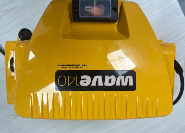
WCHWAVEBTFSK
Oct 30, 2023WAVE 140 POWER SUPPLY
Equipment Class
DTS - Digital Transmission System
WCH9995412
Jul 02, 2023Remote Control Unit for Robotic Pool Cleaner
Equipment Class
DSC - Part 15 Security/Remote Control Transmitter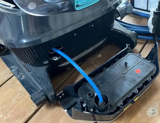
WCHLIBERTY
Apr 12, 2023Wireless Robotic Pool Cleaner with Inductive Charger
Equipment Class
DTS - Digital Transmission System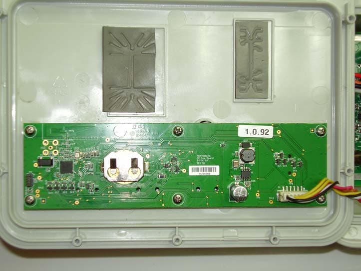
WCH99956035
Mar 05, 2015Bluetooth Communication Transceiver Module
Equipment Class
DTS - Digital Transmission System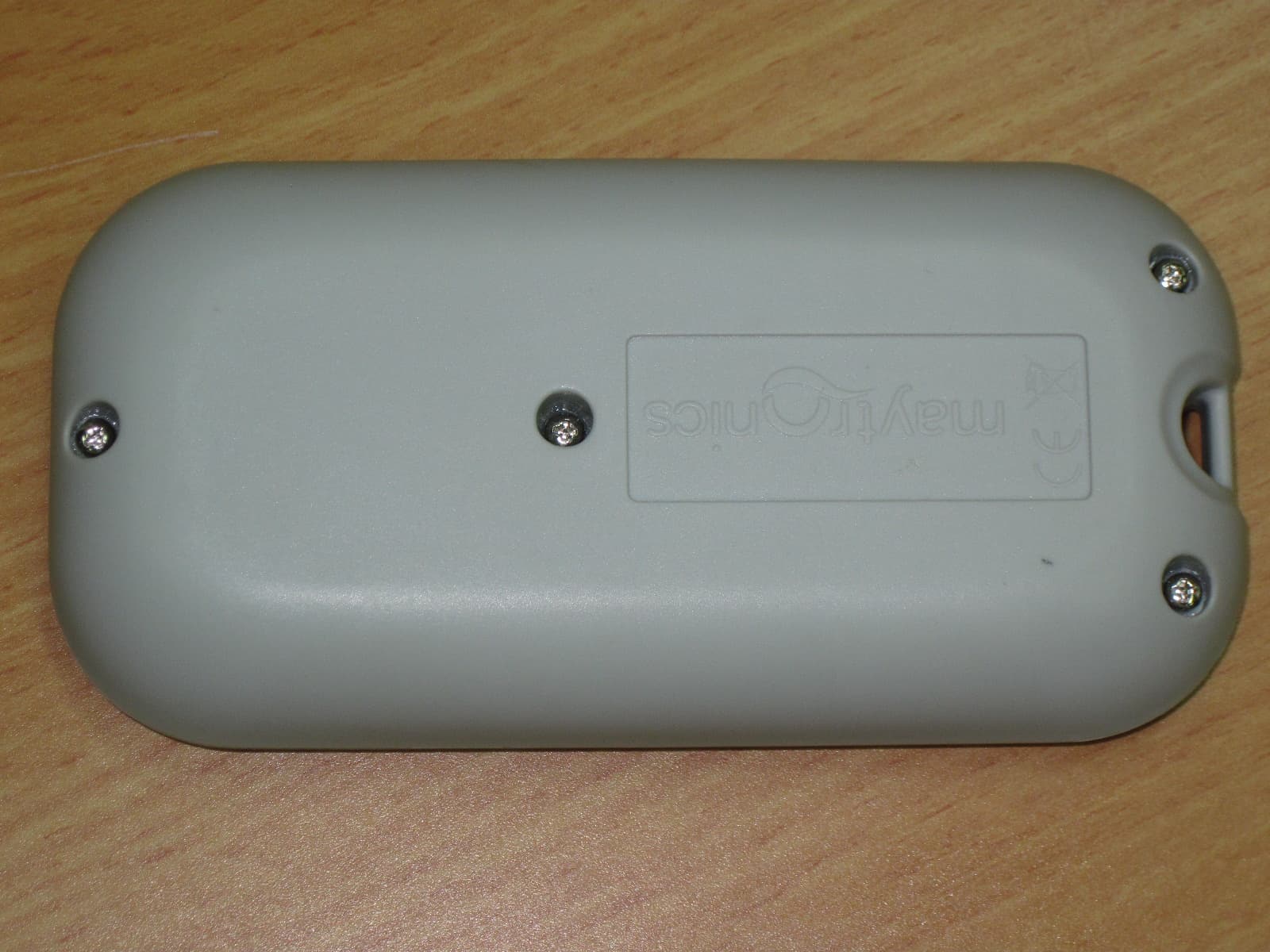
WCH99954226-7
Nov 09, 2010RCU DYNAMIC 2010
Equipment Class
DTS - Digital Transmission System