WCH9995671-5DYNAMIC DC POWER SUPPLY
Maytronics Ltd.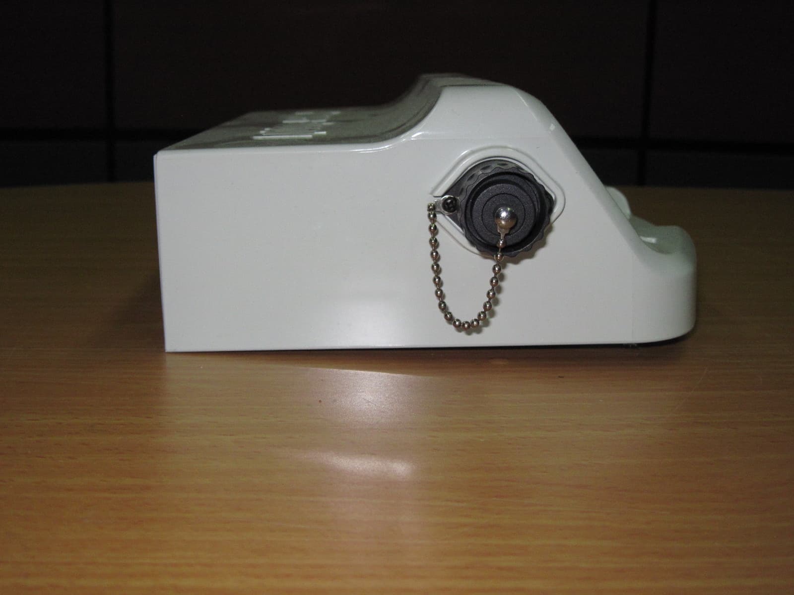
Click to zoom
Application Details
- Equipment Class
- DTS - Digital Transmission System
- Date of Grant
- Nov 08, 2010
- Application Purpose
- Original Equipment
- Date of Application
- Nov 07, 2010
- Equipment Note
- DYNAMIC DC POWER SUPPLY
- Frequency Range
- 2433.00000000 - 2433.00000000
- Company
- Maytronics Ltd.
- Country
- Israel
Documents & Files
Document Text
Text extracted from the exhibit documents filed with the FCC. Open a document above to read the original.
Users Manual
8151232 Turning the Dolphin ON to start it working 1. Plug the floating cable from the Dolphin into the power supply unit 2. Plug the electrical cable from the power supply unit into the mains Mise sous tension du Dolphin 1. Reliez le câble flotteur du Dolphin au bloc d’alimentation 2. Reliez le câble électrique du bloc d’alimentation au secteur Avviare Dolphin 1. Collegare il cavo galleggiante di Dolphin all’alimentatore elettrico 2. Collegare il cavo elettrico dell’alimentatore elettrico alla presa di rete Activar el Dolphin 1. Enchufe el cable flotador del Dolphin en la unidad de la fuente de alimentación 2. Enchufe el Cable Eléctrico de la Unidad de la fuente de alimentación en la red eléctrica Anschalten des Dolphin-Roboters 1. Verbinden Sie das Schwimmkabel des Dolphin-Roboters mit der Stromversorgungseinheit 2. Verbinden Sie das Stromkabel der Stromversorgungseinheit mit dem Stromnetz Digital “Switch-Mode” Power Supply Alimentation numérique avec « Mode Interrupteur » (“Switch-Mode”) Alimentatore digitale switching Fuente de alimentación Digital, “Switch-Mode” Digitale Stromversorgungseinheit mit Schalter Floating Cable 3. Press the ON/OFF switch on the power supply unit. The Dolphin will now start to work 3. Appuyez sur l’interrupteur de marche/ arrêt (ON/ OFF). Le Dolphin va maintenant entamer son cycle de nettoyage 3. Premere l’interruttore ON/OFF. Dolphin inizierà così a funzionare 3. Presione el interruptor de Encendido/ Apagado. El Dolphin empezará ahora a trabajar 3. Betätigen Sie den AN-/AUS-Schalter. Daraufhin beginnt der Dolphin-Roboter mit der Arbeit • Input - 100-250 AC Volts • 50-60 Hertz • 180 Watt • Output - 30 VDC • IP 54 On/Off switch Reset button Delay indicator Full filter bag indicator FCC statement NOTE: This equipment has been tested and found to comply with the limits for a Class B digital device, pursuant to part 15 of the FCC Rules. These limits are designed to provide reasonable protection against harmful interference in a residential installation. This equipment generates, uses and can radiate radio frequency energy and, if not installed and used in accordance with the instructions, may cause harmful interference to radio communications. However, there is no guarantee that interference will not occur in a particular installation. If this equipment does cause harmful interference to radio or television reception, which can be determined by turning the equipment off and on, the user is encouraged to try to correct the interference by one or more of the following measures: • Reorient or relocate the receiving antenna. • Increase the separation between the equipment and receiver. • Connect the equipment into an outlet on a circuit different from that to which the receiver is connected. • Consult the dealer or an experienced radio/TV technician for help. Changes or modifications to this equipment not expressly approved by the party responsible for compliance (Maytronics Ltd.) could void the user’s authority to operate the equipment.
Operational Description
At turn on PWS RF module goes into idle state. Sometime after turn on the power(exactly time depends on is output connected to robot or not) PWS RF module enters into receive state from main loop. If PWS RF module receives a correct RF packet, it goes into transmit state by interrupt and transmits a reply to that received packet. When transmission is over PWS, RF module goes into idle state by interrupt. Then PWS RF module enters into receive state from main loop again and over. In receive mode, if PWS RF module does not get correct RF packet in 630ms time period, it goes into the idle state by interrupt and then again enters into receive state from main loop.
Test Report
DATE: 20 September 2010 I.T.L. (PRODUCT TESTING) LTD. FCC Radio Test Report for Maytronics Ltd. Equipment under test: HG Power Supply for Dolphin Supreme M5 Dynamic DC Written by: _____________________________ D. Shidlowsky, Documentation Approved by: _____________________________ A. Sharabi, Test Engineer Approved by: _____________________________ I. Raz, EMC Laboratory Manager This report must not be reproduced, except in full, without the written permission of I.T.L. (Product Testing) Ltd. This report relates only to items tested. Test Report E95253.00 Maytronics Ltd. Page 1 of 48 FCC ACC M Ver 1.1 05Mayl 2000 Test Report E95253.00 Maytronics Ltd. Page 2 of 48 FCC ACC M Ver 1.1 05Mayl 2000 Measurement/Technical Report for Maytronics Ltd. HG Power Supply for Dolphin Supreme M5 Dynamic DC FCC ID: WCH9995671-5 This report concerns: Original Grant: X Class I Change: Class II Change: Equipment type: Digital Transmission System Limits used: 47CFR15 Section 15.247 Measurement procedure used is ANSI C63.4-2003. Application for Certification Applicant for this device: prepared by: (different from "prepared by") Ishaishou Raz Yair Hadari ITL (Product Testing) Ltd. Maytronics Ltd. Kfar Bin Nun Kibbutz Yizrael D.N. Shimshon 99780 D.N. Emek Yizrael 19350 Israel Israel e-mail [email protected] Tel: +972- 4 - 659 - 8111 Fax: +972- 4 - 652 - 2485 e-mail: [email protected] Test Report E95253.00 Maytronics Ltd. Page 3 of 48 FCC ACC M Ver 1.1 05Mayl 2000 TABLE OF CONTENTS 1. GENERAL INFORMATION ------------------------------------------------------------------------------- 5 1.1 Administrative Information ................................................................................ 5 1.2 List of Accreditations ........................................................................................ 6 1.3 Product Description .......................................................................................... 7 1.4 Test Methodology ............................................................................................. 7 1.5 Test Facility....................................................................................................... 7 1.6 Measurement Uncertainty ................................................................................ 7 2. SYSTEM TEST CONFIGURATION --------------------------------------------------------------------- 8 2.1 Justification ....................................................................................................... 8 2.2 EUT Exercise Software .................................................................................... 8 2.3 Special Accessories ......................................................................................... 8 2.4 Equipment Modifications .................................................................................. 8 2.5 Configuration of Tested System ....................................................................... 8 3. TEST SETUP PHOTOGRAPHS ------------------------------------------------------------------------- 9 4. CONDUCTED EMISSION DATA ---------------------------------------------------------------------- 10 4.1 Test Specification ........................................................................................... 10 4.2 Test Procedure ............................................................................................... 10 4.3 Measured Data ............................................................................................... 10 4.4 Test Instrumentation Used, Conducted Measurement .................................. 15 5. 6DB MINIMUM BANDWIDTH -------------------------------------------------------------------------- 16 5.1 Test Specification ........................................................................................... 16 5.2 Test procedure ............................................................................................... 16 5.3 Test Results .................................................................................................... 17 5.4 Test Equipment Used. .................................................................................... 18 6. RADIATED POWER OUTPUT ------------------------------------------------------------------------- 19 6.1 Test Specification ........................................................................................... 19 6.2 Test procedure ............................................................................................... 19 6.3 Results Calculation ......................................................................................... 20 6.4 Test Equipment Used. .................................................................................... 21 7. BAND EDGE ------------------------------------------------------------------------------------------------ 22 7.1 Test procedure ............................................................................................... 22 7.2 Results table ................................................................................................... 24 7.3 Test Equipment Used. .................................................................................... 25 8. RADIATED EMISSION, 9 KHZ – 30 MHZ ----------------------------------------------------------- 26 8.1 Test Specification ........................................................................................... 26 8.2 Test Procedure ............................................................................................... 26 8.3 Measured Data ............................................................................................... 26 8.4 Test Instrumentation Used, Radiated Measurements .................................... 27 8.5 Field Strength Calculation .............................................................................. 27 9. SPURIOUS RADIATED EMISSION 30 – 25000 MHZ -------------------------------------------- 28 9.1 Test Specification ..........…
Text truncated - open the document above for the full version.
Contact Information
Applicant
Yair Hadari(Manager of hardware and software development)
Test Firm
Israel Testing LaboratoriesIIan Cohen
Technical Specifications
| # | Rule Parts | Frequency Range | Power Output |
|---|---|---|---|
| 1 | 15C | 2.43 GHz - 2.43 GHz | 1.00 mW |
Other Applications from Maytronics Ltd.
WCHSKIM2
Feb 10, 2026Pool surface cleaner
Equipment Class
DTS - Digital Transmission System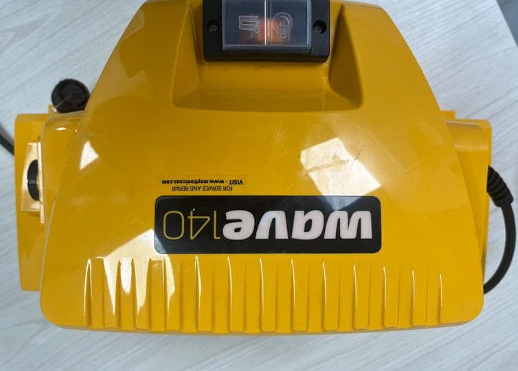
WCHWAVEBTFSK
Oct 30, 2023WAVE 140 POWER SUPPLY
Equipment Class
DTS - Digital Transmission System
WCH9995412
Jul 02, 2023Remote Control Unit for Robotic Pool Cleaner
Equipment Class
DSC - Part 15 Security/Remote Control Transmitter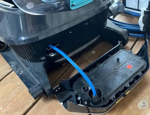
WCHLIBERTY
Apr 12, 2023Wireless Robotic Pool Cleaner with Inductive Charger
Equipment Class
DTS - Digital Transmission System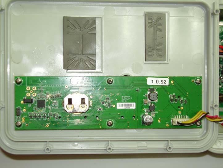
WCH99956035
Mar 05, 2015Bluetooth Communication Transceiver Module
Equipment Class
DTS - Digital Transmission System