WIBTZW017Z-wave enabled wireless keypad
Residential Control Systems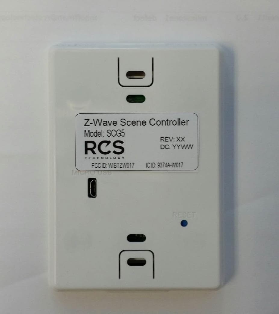
Click to zoom
Application Details
- Equipment Class
- DXX - Part 15 Low Power Communication Device Transmitter
- Date of Grant
- Jul 09, 2015
- Application Purpose
- Original Equipment
- Date of Application
- Jul 09, 2015
- Equipment Note
- Z-wave enabled wireless keypad
- Frequency Range
- 908.40000000 - 916.00000000
- Company
- Residential Control Systems
- Country
- United States
Documents & Files
Document Text
Text extracted from the exhibit documents filed with the FCC. Open a document above to read the original.
Users Manual
Model SCG5 Z-Wave Keypad INSTALLATION AND OPERATION MANUAL DCN: 141-02273-01 5/19/15 RCS DCN: 141-02273-01 5/19/15 2 Model: SCG5 Z-Wave Keypad This manual applies to the following product revisions or later revisions up to the next manual revision release: Product Part No: Firmware Revision Z-Wave Keypad 001-02273 1.00.3 Document Revision History Revision Date Changes 01 10/20/10 Original release Product Specifications Product Model: SCG5 Product: Scene Control Z-Wave RF communications enabled Keypad Size: 3.5” wide x 4.5” height x 1.2” depth Display: Graphical LCD, 2.75” x 1.5”, 64x128 pixel Backlight: Yes, Blue/white, Controllable, on, off, timeout Contrast: Adjustable on screen Buttons: 8 Power: 2 AAA Alkaline Communications: Z-Wave RF DCN: 141-02273-01 5/19/15 3 Table of Contents Overview ...................................................................................................................................................... 4 Z-Wave® Installation ................................................................................................................................... 5 Inclusion and Exclusion ............................................................................................................................. 5 Power ......................................................................................................................................................... 5 FCC ............................................................................................................................................................... 6 DCN: 141-02273-01 5/19/15 4 Overview Z-Wave Keypad The Z-Wave Keypad provides for typical Keypad control plus has the added feature of Z-Wave communications for remote control. The Keypad has a large, backlit graphical display and control buttons. The Keypad can display multiple screens for different functions of the Keypad. Display operation Keypad control screen Normally the Keypad displays the Keypad control screen as shown above. Minimized Display Mode Optionally, you can set the Keypad to timeout and show a blank screen. Backlight The Keypad has a backlit display for low light and night visibility. It can be set to remain on constantly, or to turn off after a 20-120 second delay. These are selectable in the User Settings menu. Function Control Buttons The Keypads buttons are “Soft Keys” meaning that they change functions when you change screens. The function of the button is defined by “on-screen labels” that are dynamic and change when you change screens Function Control Buttons On-screen dynamic button labels DCN: 141-02273-01 5/19/15 5 Z-Wave® Installation Z-Wave controllers from various manufacturers may support the Z-Wave Wall Controller Device class used by the RCS Z-WAVE Keypad. The following procedure will allow the Keypad to be added to a Z- Wave network. General Programming Procedure (for controllers supporting the Keypad device class): 1. Set your primary controller to Include mode, to add the Keypad as a node on your network (see your controller’s user manual for detailed instructions). 2. In the Keypad’s Main Menu, scroll down to the ZWave Install item. Select the item. 3. Press the YES button in the ZWave Install screen. Your controller will indicate the Keypad was successfully added to its network (see your controller’s user manual for details). Also you can check if the Keypad was successfully added to the network by checking the ZHID (Home ID) and ZNID (Node ID) located in the Keypad Info screen. For other specific tasks such as adding the Keypad to Scenes or Groups, or deleting the Keypad from an existing network, use the Z-Wave Install procedure. Note: Before adding the Keypad to a Z-Wave Network, check that it does not already belong to one by viewing the Home and Zone ID’s located in the Keypad Info screen. An un-configured Keypad should show zeros for both the Home and Zone IDs. Consult your controller’s user manual for details on removing a device from a Z-Wave network. Inclusion and Exclusion Inclusion or exclusion is started by putting the controller into add node or remove node state and performing the General Programming Procedure outlined above. As part of the process, the Keypad sends a node information frame at normal power. Low power inclusion or low power exclusion is not possible. Power The Keypad requires 2 AAA Alkaline batteries DCN: 141-02273-01 5/19/15 6 FCC/IC INFORMATION TO USER This device complies with Part 15 of the FCC Rules. Operation is subject to the following two conditions: (1) This device may not cause harmful interference, and (2) This device must accept any interference received, including interference that may cause undesired operation. This equipment has been tested and found to comply with the limits for Class B Digital Device, pursuant to Part 15 of the FCC Rules. These limits are designed to provide reasonable protection against harmful interference in a residential installation. This equipment generates and can radiate radio frequency energy and, if not installed and used in accordance with the instructions, may cause harmful interference to radio communications. However, there is no guarantee that interference will not occur in a particular installation. If this equipment does cause harmful interference to radio or television reception, which can be determined by turning the equipment off and on, the user is encouraged to try to correct the interference by one or more of the following measures. Reorient or relocate the receiving antenna Increase the separation between the equipment and receiver Connect the equipment into an outlet on a circuit different from that to which the receiver is connected Consult the dealer or an experienced radio/TV technician for help Any changes or modifications not expressly approved by the party responsible for compliance could void the user’s authority to operate the equipment. This device complies with Industry Canada licens…
Text truncated - open the document above for the full version.
Cover Letter(s)
Residential Control Systems Inc 11481 Sunrise Gold Circle Suite 1 Rancho Cordova, CA 95742 Nemko Canada Inc 303 River Road Ottawa, Ontario, Canada K1V 1H2 Attn: Director of Certification Authority to Act as Agent FCC On our behalf, I appoint Jenny Gibbs of Nemko USA, Inc. 2650 FM 407, Suite 255P Bartonville, TX 76226, to act as our agent in the preparation of this application for equipment certification. I certify that submitted documents properly describe the device or system for which equipment certification is sought. I also certify that each unit manufactured, imported or marketed, as defined in FCC regulations will have affixed to it a label identical to that submitted for approval with this application. In signing this letter, Applicant certifies that neither the applicant nor any party to the application is not subject to a denial of Federal benefits, that include FCC benefits, pursuant to Section 5301 of the Anti-Drug Abuse Act of 1988, 21 U.S.C. § 862 because of a conviction for possession or distribution of a controlled substance. See 47 CFR 1.2002(b) for the definition of a "party" for these purposes. For instances where our authorized agent signs the application for certification on our behalf, I acknowledge that all responsibility for complying with the terms and conditions for certification, as specified by Nemko Canada Inc, still resides at 11481 Sunrise Gold Circle Suite 1, Rancho Cordova CA 95742 Dated this 20 Day of May 20 15 Agency agreement expiration date: 1 year By: Michael Hoffman Signature Printed Title: VP Engineering On behalf of : Telephone: 916-635-6784 x240
Cover Letter(s)
SS 11481 Sunrise Gold Circle, Ste 1 Rancho Cordova, CA 95742 916.635.6784 www.rcstechnology.com 6/18/15 Nemko Canada Inc. 303 River Road Ottawa, Ontario, Canada K1V 1H2 FCC ID: WIBTZW017 Product Name: SCG5 Request for Confidentiality Pursuant to Sections 0.457 and 0.459 of the commission’s rules, we hereby request that the following documents be held under long term confidentiality: Schematics, Parts List, Operating Description, Block Diagrams These materials contain trade secrets and proprietary information and are not customarily released to the public. The public disclosure of this information might be harmful to the company and provide unjustified benefits to our competitors. Dated this 20 Day of May 20 15 By: Michael Hoffman Signature Printed Title: VP Engineering On behalf of : Residential Control Systems Inc Telephone: 916-635-6784 x240
Cover Letter(s)
SS 11481 Sunrise Gold Circle, Ste 1 Rancho Cordova, CA 95742 916.635.6784 www.rcstechnology.com 6/18/15 Model Difference Letter This is to acknowledge that the models SCG5, NX1000 and GC-SCG5 both physically and electronically, as well as internal and external are same. There are no differences. Please contact me if you have any other questions. Michael Hoffman
External Photos
RCS SCG5 Exterior Photos Page 1 05/26/15 RCS SCG5 Exterior Photos Page 2 05/26/15
ID Label/Location Info
Label Location: Inside of Enclosure Back Label Location: Inside of Enclosure Back Label Location: Inside of Enclosure Back
Internal Photos
RCS SCG5 Product Photos Page 1 RCS SCG5 Product Photos Page 2 RCS SCG5 Product Photos Page 3 RF Module Assembly
Test Report
Nemko Test Report: 2015 283053A FCC15249 Applicant: Residential Control Systems 12625 Danielson Ct.Suite 102 Poway CA 92064 Equipment Under Test: SCG5 (E.U.T.) FCC Identifier: WIBTZW017 Industry Canada Identifier: 9374A-W017 In Accordance With: FCC Part 15, Subpart C, 15.249 and Industry Canada RSS-210, Issue 8 Operation within the bands 902-928 MHz, 2400-2483.5 MHz, 5725-5875 MHz, and 24.0-24.25 GHz. Tested By: Nemko USA, Inc. 2210 Faraday Ave, Suite 150 Carlsbad, CA 92008 TESTED BY: DATE: 04 May 2015 David Light, Wireless Engineer APPROVED BY: DATE: 24 June 2015 Total Number of Pages: 17 Nemko USA, Inc. CFR 47, PART 15, Paragraph 15.249 and Industry Canada RSS-210, Issue 8 Operation within the bands 902-928 MHz, 2400-2483.5 MHz, 5725-5875 MHz, and 24.0-24.25 GHz. EQUIPMENT: SCG5 REPORT NO.: 2015 283053A FCC15249 Page 2 of 17 Table of Contents SECTION 1. SUMMARY OF TEST RESULTS 3 SECTION 2. GENERAL EQUIPMENT SPECIFICATION 5 SECTION 3. TRANSMIT RADIATED EMISSIONS 6 SECTION 4. TEST EQUIPMENT LIST 14 ANNEX A TEST DIAGRAMS 15 Nemko USA, Inc. CFR 47, PART 15, Paragraph 15.249 and Industry Canada RSS-210, Issue 8 Operation within the bands 902-928 MHz, 2400-2483.5 MHz, 5725-5875 MHz, and 24.0-24.25 GHz. EQUIPMENT: SCG5 REPORT NO.: 2015 283053A FCC15249 Page 3 of 17 Section 1. Summary Of Test Results Manufacturer: Residential Control Systems Model No.: SCG5 Serial No.: None General: All measurements are traceable to national standards. These tests were conducted on a sample of the equipment for the purpose of demonstrating compliance with FCC Paragraph 15.249 and Industry Canada RSS-210, Issue 8. All tests were conducted using measurement procedure ANSI C63.10-2013. Radiated Emissions were made on a semi-anechoic chamber. New Submission Production Unit Class II Permissive Change Pre-Production Unit THIS TEST REPORT RELATES ONLY TO THE ITEM(S) TESTED. THE FOLLOWING DEVIATIONS FROM, ADDITIONS TO, OR EXCLUSIONS FROM THE TEST SPECIFICATIONS HAVE BEEN MADE. See “ Summary of Test Data”. NVLAP Lab Code 200116-0 Nemko USA, Inc. authorizes the above named company to reproduce this report provided it is reproduced in its entirety, for use by the company’s employees only. This report must not be used to claim product certification, approval, or endorsement by NVLAP, NIST, or any agency of the Federal Government. Nemko USA, Inc. is a NVLAP accredited laboratory. Any use which a third party makes of this report, or any reliance on or decisions to be made based on it, are the responsibility of such third parties. Nemko USA, Inc. accepts no responsibility for damages, if any, suffered by any third party as a result of decisions made or actions based on this report. This report applies only to the items tested. Nemko USA, Inc. CFR 47, PART 15, Paragraph 15.249 and Industry Canada RSS-210, Issue 8 Operation within the bands 902-928 MHz, 2400-2483.5 MHz, 5725-5875 MHz, and 24.0-24.25 GHz. EQUIPMENT: SCG5 REPORT NO.: 2015 283053A FCC15249 Page 4 of 17 Summary Of Test Data NAME OF TEST PARA. NO. RESULT Conducted Emissions 15.207 / RSS-Gen NA Radiated Emissions 15.249 / RSS-210 A2.9 Complies Footnotes For N/A’s: The EUT is battery powered. Nemko USA, Inc. CFR 47, PART 15, Paragraph 15.249 and Industry Canada RSS-210, Issue 8 Operation within the bands 902-928 MHz, 2400-2483.5 MHz, 5725-5875 MHz, and 24.0-24.25 GHz. EQUIPMENT: SCG5 REPORT NO.: 2015 283053A FCC15249 Page 5 of 17 Section 2. General Equipment Specification Frequency Range: 902 to 928 MHz Operating Frequency(ies) of Sample: 908.4 to 916 MHz Number of Channels: 2 Modulation Type: 2FSK (Lower Channel) 2GFSK (Upper Channel) Emission Designator: 86K0F2D (Lower Channel) 110KF2D (Upper Channel) Hardware Version: Rev C Firmware Version: 1.1.6 User Frequency Adjustment: Integral Antenna Yes No Description of EUT Scene control keypad for lighting control. Nemko USA, Inc. CFR 47, PART 15, Paragraph 15.249 and Industry Canada RSS-210, Issue 8 Operation within the bands 902-928 MHz, 2400-2483.5 MHz, 5725-5875 MHz, and 24.0-24.25 GHz. EQUIPMENT: SCG5 REPORT NO.: 2015 283053A FCC15249 Page 6 of 17 Section 3. Transmit Radiated Emissions NAME OF TEST: Transmit Radiated Emissions PARA. NO.: 15.249 TESTED BY: David Light DATE: 20 April 2015 Minimum Standard: Para no. 15.249 (a) The field strengths shall not exceed the following: Carrier (MHz) Field Strength (mV/m) Field Strength (dBV) Harmonic (μV/m) Harmonic (dBV) 902-928 50 94 500 54 2400-2483.5 50 94 500 54 5725-5875 50 94 500 54 24000-24250 250 108 2500 68 (b) Field strength limits are specified at a distance of 3 metres. (c) Emissions radiated outside of the specified frequency bands, except for harmonics, shall be attenuated by at least 50 dB below the level of the fundamental or to the general radiated limits of 15.209 whichever is the less attenuation. (d) ...for frequencies above 1000 MHz, the above field strength limits are based on average limits. However, the peak field strength of any emission shall not exceed the maximum permitted average limits specified above by more than 20 dB under any condition of modulation. Test Results: Complies Measurement Data: See attached table and graphs. Meas.Ant.Atten.MeterAntennaPathRFCorrectedSpec.CR/SLPass Freq.Pol.ReadingFactorLossGainReadinglimitDiff.Fail (MHz)(H/V)(dB)(dBuV)(dB)(dB)(dB)(dBuV/m)(dBuV/m)(dB)Unc.Comment 908.4V0.056.323.53.70.083.594.0-10.5Pass 908.4H0.063.023.53.70.090.294.0-3.8Pass 916.0V0.059.223.53.70.086.494.0-7.6Pass 916.0H0.064.023.53.70.091.294.0-2.8Pass Nemko USA, Inc. CFR 47, PART 15, Paragraph 15.249 and Industry Canada RSS-210, Issue 8 Operation within the bands 902-928 MHz, 2400-2483.5 MHz, 5725-5875 MHz, and 24.0-24.25 GHz. EQUIPMENT: SCG5 REPORT NO.: 2015 283053A FCC15249 Page 7 of 17 Test Data - Radiated Emissions Lower Channel Nemko USA, Inc. - Car lsbad, CA FCC 3m Class B 30M Hz -1GHz Vertical Scan 30.0M100.0M1.0G Frequency -10.0 0 10.0 20.0 30.0 40.0 50.0 60.0 70.0 80.0 Amplitude (dbuV/m) Nemko USA, Inc. - Car lsbad, CA FCC 3m Class B …
Text truncated - open the document above for the full version.
Contact Information
Applicant
Michael Hoffman(VP Engineering)
Test Firm
Nemko USA, Inc. - San Diego EMC DivisionJan Blomgren
[email protected]760-444-3500
Technical Specifications
| # | Rule Parts | Frequency Range | Power Output |
|---|---|---|---|
| 1 | 15C | 908.4 MHz - 916 MHz | - |
Other Applications from Residential Control Systems
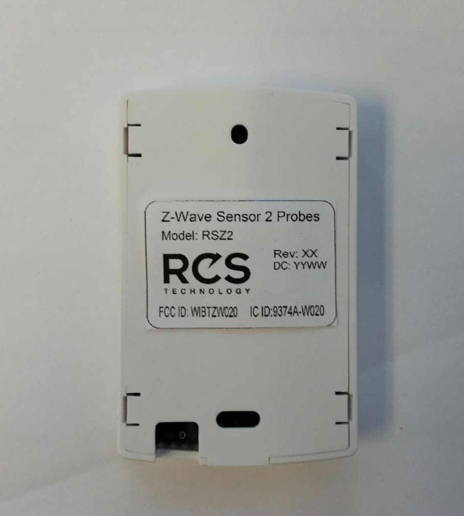
WIBTZW020
Jul 09, 2015Z-wave enabled wireless sensor
Equipment Class
DXX - Part 15 Low Power Communication Device Transmitter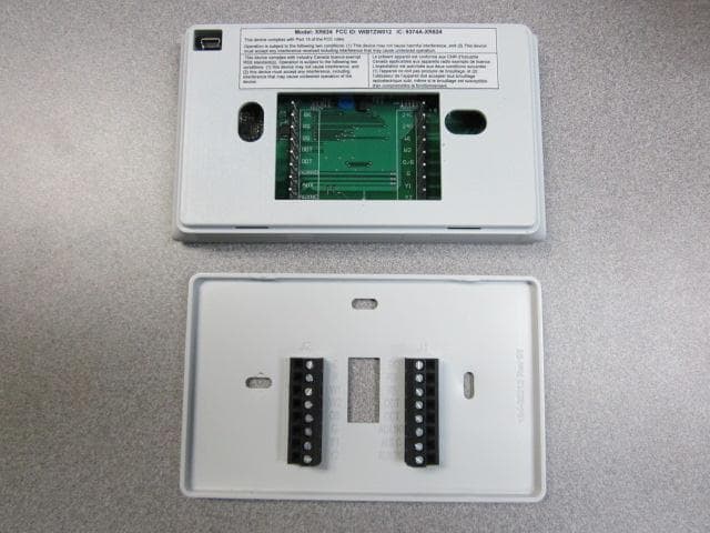
WIBTZW012
Mar 11, 2013Wireless Thermostat
Equipment Class
DXT - Part 15 Low Power Transceiver, Rx Verified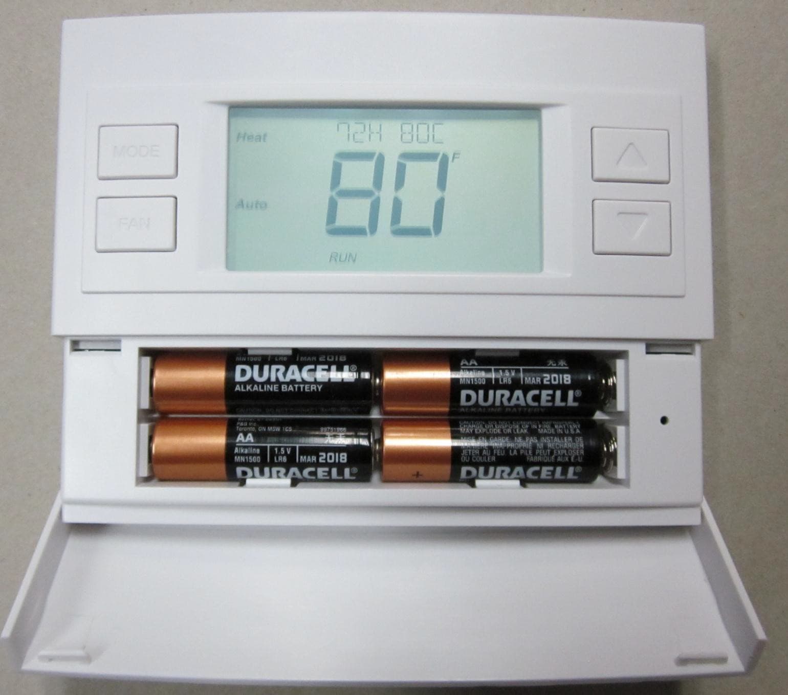
WIBTZW011
Jun 04, 2012Wireless Thermostat
Equipment Class
DXX - Part 15 Low Power Communication Device Transmitter
WIBTZW008
Nov 08, 2010Wireless Thermostat
Equipment Class
DXX - Part 15 Low Power Communication Device Transmitter