WL6-TC10RA3Tablet PC
ELITEGROUP COMPUTER SYSTEMS CO., LTD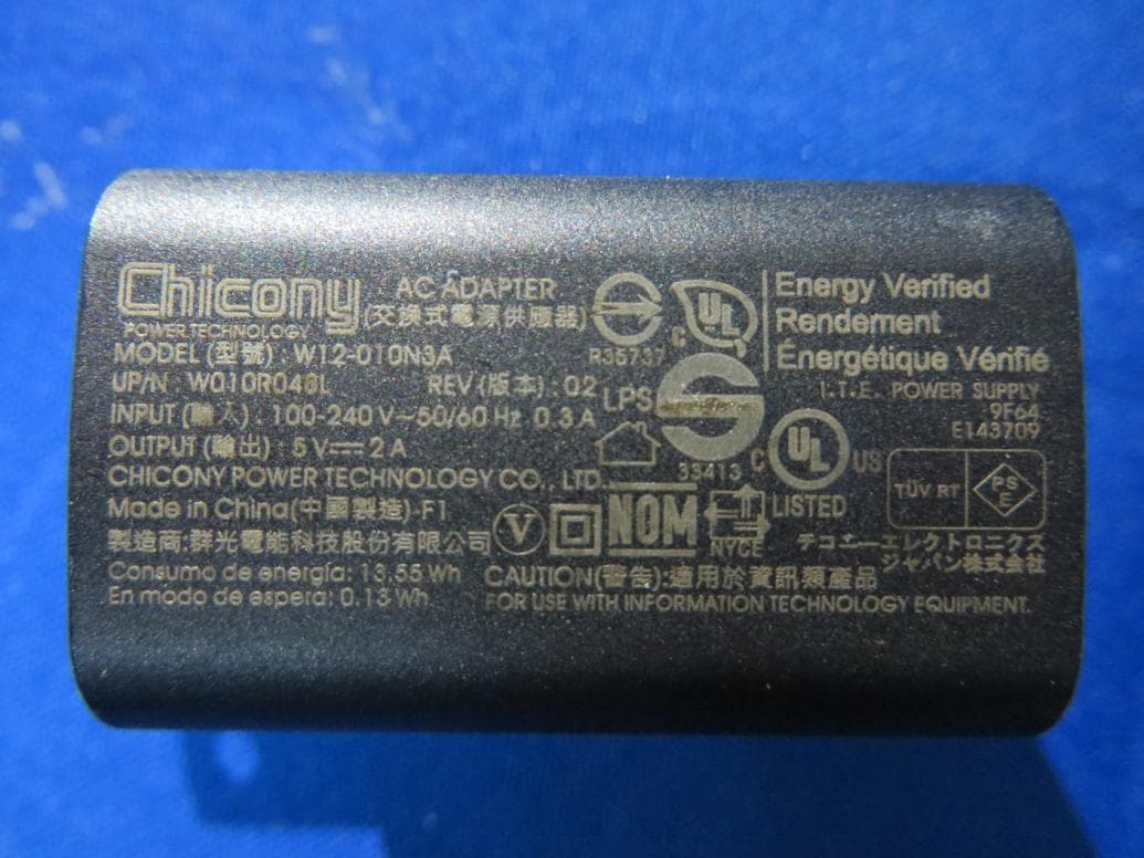
Click to zoom
Application Details
- Equipment Class
- DSS - Part 15 Spread Spectrum Transmitter
- Date of Grant
- May 14, 2015
- Application Purpose
- Original Equipment
- Date of Application
- May 14, 2015
- Equipment Note
- Tablet PC
- Frequency Range
- 2402.00000000 - 2480.00000000
- Country
- Taiwan
Documents & Files
Document Text
Text extracted from the exhibit documents filed with the FCC. Open a document above to read the original.
Users Manual
Quick Start Guide For Android Tablet TC10RA3 1 Federal Communication Commission Interference Statement This equipment has been tested and found to comply with the limits for a Class B digital device, pursuant to Part 15 of the FCC Rules. These limits are designed to provide reasonable protection against harmful interference in a residential installation. This equipment generates, uses and can radiate radio frequency energy and, if not installed and used in accordance with the instructions, may cause harmful interference to radio communications. However, there is no guarantee that interference will not occur in a particular installation. If this equipment does cause harmful interference to radio or television reception, which can be determined by turning the equipment off and on, the user is encouraged to try to correct the interference by one of the following measures: - Reorient or relocate the receiving antenna. - Increase the separation between the equipment and receiver. - Connect the equipment into an outlet on a circuit different from that to which the receiver is connected. - Consult the dealer or an experienced radio/TV technician for help. Caution: Any changes or modifications not expressly approved by the party responsible for compliance could void the user's authority to operate this equipment. This device complies with Part 15 of the FCC Rules. Operation is subject to the following two conditions: (1) This device may not cause harmful interference, and (2) This device must accept any interference received, including interference that may cause undesired operation. 0.469 2 RF Exposure Information (SAR) This device meets the government’s requirements for exposure to radio waves. This device is designed and manufactured not to exceed the emission limits for exposure to radio frequency (RF) energy set by the Federal Communications Commission of the U.S. Government. The exposure standard employs a unit of measurement known as the Specific Absorption Rate, or SAR. The SAR limit set by the FCC is 1.6 W/kg. Tests for SAR are conducted using standard operating positions accepted by the FCC with the EUT transmitting at the specified power level in different channels. The highest SAR value for the device as reported to the FCC is W/kg when placed next to the body. CAUTION Risk of explosion if battery is replaced by an incorrect type. Dispose of used batteries according to the instructions. Attention: Teachers, Parents and Adult Supervisors This product is an educational tool designed for school children, ages 6 and up. There must be supervision by an adult on school children under 10 when using this tablet. It is a must to have a thorough explanation to students on safe and proper handling of the tablet, power supply, battery pack, and power cord. 3 Be sure to keep the power cord away from younger children Please ensure that students understand the following: ! As with all electrical products, precautions should be observed during handling and use to prevent electric shock. The power supply (adapter) should not be handled by the children.” ! Emphasize to students that this device is an educational tool and not a toy. The tablet, power supply, battery pack or power cord should not be dropped, crushed, stepped on or otherwise abused. ! Ensure students understand the safe and proper handling of power cord and power supply. Misuse could result in serious injury. ! The teacher, parent or adult supervisor should periodically inspect the tablet; power supply and power cord for damage and replace it, if necessary. ! Students should report any damage or loose parts to their teacher, parents or adult supervisor, immediately. ! Do not leave the tablet plugged in or “on” when enclosed in a non-vented container, such as a school backpack, as overheating may occur. ! It is recommended that students should take a 5-minute break every 30 minutes of use. 4 Safety Precautions The following are lists of precautionary measure the students must understand before using this tablet inside the classroom or home environment: 1. Do not place near the fire or other sources of heat. 2. Do not expose to magnetic fields. 3. Do not expose to direct sunlight. 4. Do not expose to rain or moisture. 5. Do not place heavy objects to add heavy pressure on the tablet. 6. Do not drop the tablet. 5 Réglementation de la commission fédérale des communic ations sur les interférences Cet équipement a été testé et déclaré conforme aux normes des appareils numériques de Classe B, conformément à l'article 15 du règlement de la FCC. Ces limites sont conçues pour offrir une protection raisonnable contre les interférences néfastes dans une installation résidentielle. Cet appareil génère, utilise, et peut diffuser de l'énergie radioélectrique et, s'il n’est pas installé et utilisé conformément aux instructions, il peut causer des interférences nuisibles aux communications radio. Cependant, il n'est pas garanti que des interférences ne se produiront pas dans une installation particulière. Si cet appareil provoque des parasites dangereux qui affectent la réception radio ou de télévision, ce que vous pouvez déterminer en éteignant et en rallumant l'appareil, l'utilisateur est encouragé à essayer de corriger ces interférences en employant l'une des méthodes suivantes: - Réorientez ou déplacez l'antenne de réception. - Eloignez le matériel du récepteur. - Branchez le matériel à une prise fonctionnant sur un circuit différent de celui sur lequel le récepteur est connecté. - Consulter le revendeur ou un technicien radio ou télévision expérimenté. Attention : Tous changements ou modifications n'ayant pas été expressément approuvés par l'organisme responsable de la conformité peuvent enlever tout droit à l'utilisateur de faire fonctionner ce matériel. Cet appareil est conforme à la partie 15 des règles de la FCC. L’utilisation de cet appareil est soumise aux deux conditions suivantes : 6 (1) Ce matériel ne doit pas engendrer d'interférences nuis…
Text truncated - open the document above for the full version.
External Photos
External Photo (1) EUT Photo (2) EUT Photo (3) EUT Photo (4) EUT Photo (5) EUT Photo (6) EUT Photo (7) EUT Photo (Adapter #1) (8) EUT Photo (Adapter #1) (9) EUT Photo (Adapter #2) (10) EUT Photo (Adapter #2) (11) EUT Photo
ID Label/Location Info
Label Label Location
Internal Photos
Internal Photo (1) EUT Photo (2) EUT Photo (3) EUT Photo (4) EUT Photo (5) EUT Photo (6) EUT Photo (7) EUT Photo (8) EUT Photo (9) EUT Photo (10) EUT Photo (11) EUT Photo (12) EUT Photo (13) EUT Photo (14) EUT Photo (15) EUT Photo (16) EUT Photo (17) EUT Photo
Test Report
Report No.: 1503RSU00103 FCC ID: WL6-TC10RA3 Page Number: 51 of 95 7.9.4. Test Setup 9kHz ~ 30MHz Test Setup: 30MHz ~ 1GHz Test Setup: Report No.: 1503RSU00103 FCC ID: WL6-TC10RA3 Page Number: 52 of 95 1GHz ~ 25GHz Test Setup: Report No.: 1503RSU00103 FCC ID: WL6-TC10RA3 Page Number: 53 of 95 7.9.5. Test Result Test Mode: DH5 Test Site: AC1 Test Channel: 00 Test Engineer: Roy Cheng Remark: 1. Average measurement was not performed if peak level lower than average limit. 2. Other frequency was 20dB below limit line within 1-18GHz, there is not show in the report. Mark Frequency (MHz) Reading Level (dBμV) Factor (dB) Measure Level (dBμV/m) Limit (dBμV/m) Margin (dB) Detector Polarization 3746.4 36.9 -0.4 36.5 74.0 -37.5 Peak Horizontal 4978.3 35.9 3.0 38.9 74.0 -35.1 Peak Horizontal * 6235.5 35.4 4.7 40.1 77.7 -37.6 Peak Horizontal * 8672.4 35.4 8.9 44.3 77.7 -33.4 Peak Horizontal 3746.3 36.9 -0.4 36.5 74.0 -37.5 Peak Vertical 4952.4 35.1 2.9 38.0 74.0 -36.0 Peak Vertical * 6855.0 35.1 6.3 41.4 77.7 -36.3 Peak Vertical * 8743.9 35.2 9.0 44.2 77.7 -33.5 Peak Vertical Note 1: “*” is not in restricted band, its limit is 20dBc of the fundamental emission level (97.7dBμV/m). Note 2: Measure Level (dBμV/m) = Reading Level (dBμV) + Factor (dB) Factor (dB) = Cable Loss (dB) + Antenna Factor (dB/m) - Pre_Amplifier Gain (dB) Report No.: 1503RSU00103 FCC ID: WL6-TC10RA3 Page Number: 54 of 95 Test Mode: DH5 Test Site: AC1 Test Channel: 39 Test Engineer: Roy Cheng Remark: 1. Average measurement was not performed if peak level lower than average limit. 2. Other frequency was 20dB below limit line within 1-18GHz, there is not show in the report. Mark Frequency (MHz) Reading Level (dBμV) Factor (dB) Measure Level (dBμV/m) Limit (dBμV/m) Margin (dB) Detector Polarization 3746.3 36.6 -0.4 36.2 74.0 -37.8 Peak Horizontal 4982.5 35.6 3.0 38.6 74.0 -35.4 Peak Horizontal * 6524.5 35.4 5.9 41.3 77.8 -36.5 Peak Horizontal * 8652.3 36.2 8.8 45.0 77.8 -32.8 Peak Horizontal 3752.4 37.0 -0.4 36.6 74.0 -37.4 Peak Vertical 4952.2 35.8 2.9 38.7 74.0 -35.3 Peak Vertical * 6253.5 35.6 4.7 40.3 77.8 -37.5 Peak Vertical * 8652.2 35.3 8.8 44.1 77.8 -33.7 Peak Vertical Note 1: “*” is not in restricted band, its limit is 20dBc of the fundamental emission level (97.8dBμV/m). Note 2: Measure Level (dBμV/m) = Reading Level (dBμV) + Factor (dB) Factor (dB) = Cable Loss (dB) + Antenna Factor (dB/m) - Pre_Amplifier Gain (dB) Report No.: 1503RSU00103 FCC ID: WL6-TC10RA3 Page Number: 55 of 95 Test Mode: DH5 Test Site: AC1 Test Channel: 78 Test Engineer: Roy Cheng Remark: 1. Average measurement was not performed if peak level lower than average limit. 2. Other frequency was 20dB below limit line within 1-18GHz, there is not show in the report. Mark Frequency (MHz) Reading Level (dBμV) Factor (dB) Measure Level (dBμV/m) Limit (dBμV/m) Margin (dB) Detector Polarization 3742.6 37.6 -0.4 37.2 74.0 -36.8 Peak Horizontal 4873.3 34.8 2.7 37.5 74.0 -36.5 Peak Horizontal * 6042.3 35.1 4.1 39.2 77.8 -38.6 Peak Horizontal * 8652.4 35.9 8.8 44.7 77.8 -33.1 Peak Horizontal 3841.6 36.2 0.0 36.2 74.0 -37.8 Peak Vertical 4907.5 34.7 2.7 37.4 74.0 -36.6 Peak Vertical * 6258.5 35.2 4.8 40.0 77.8 -37.8 Peak Vertical * 8652.5 35.0 8.8 43.8 77.8 -34.0 Peak Vertical Note 1: “*” is not in restricted band, its limit is 20dBc of the fundamental emission level (97.8dBμV/m). Note 2: Measure Level (dBμV/m) = Reading Level (dBμV) + Factor (dB) Factor (dB) = Cable Loss (dB) + Antenna Factor (dB/m) - Pre_Amplifier Gain (dB) Report No.: 1503RSU00103 FCC ID: WL6-TC10RA3 Page Number: 56 of 95 Test Mode: 2DH5 Test Site: AC1 Test Channel: 00 Test Engineer: Roy Cheng Remark: 1. Average measurement was not performed if peak level lower than average limit. 2. Other frequency was 20dB below limit line within 1-18GHz, there is not show in the report. Mark Frequency (MHz) Reading Level (dBμV) Factor (dB) Measure Level (dBμV/m) Limit (dBμV/m) Margin (dB) Detector Polarization 3748.3 36.8 -0.4 36.4 74.0 -37.6 Peak Horizontal 4925.4 35.5 2.8 38.3 74.0 -35.7 Peak Horizontal * 6534.9 36.2 5.9 42.1 81.3 -39.2 Peak Horizontal * 8682.0 35.6 9.0 44.6 81.3 -36.7 Peak Horizontal 3742.5 36.8 -0.4 36.4 74.0 -37.6 Peak Vertical 4906.4 35.6 2.7 38.3 74.0 -35.7 Peak Vertical * 6742.6 36.1 5.7 41.8 81.3 -39.5 Peak Vertical * 8626.3 35.8 8.8 44.6 81.3 -36.7 Peak Vertical Note 1: “*” is not in restricted band, its limit is 20dBc of the fundamental emission level (101.3dBμV/m). Note 2: Measure Level (dBμV/m) = Reading Level (dBμV) + Factor (dB) Factor (dB) = Cable Loss (dB) + Antenna Factor (dB/m) - Pre_Amplifier Gain (dB) Report No.: 1503RSU00103 FCC ID: WL6-TC10RA3 Page Number: 57 of 95 Test Mode: 2DH5 Test Site: AC1 Test Channel: 39 Test Engineer: Roy Cheng Remark: 1. Average measurement was not performed if peak level lower than average limit. 2. Other frequency was 20dB below limit line within 1-18GHz, there is not show in the report. Mark Frequency (MHz) Reading Level (dBμV) Factor (dB) Measure Level (dBμV/m) Limit (dBμV/m) Margin (dB) Detector Polarization 3784.3 37.1 -0.3 36.8 74.0 -37.2 Peak Horizontal 4762.5 36.4 2.6 39.0 74.0 -35.0 Peak Horizontal * 6574.8 34.5 6.0 40.5 80.1 -39.6 Peak Horizontal * 8653.3 35.2 8.8 44.0 80.1 -36.1 Peak Horizontal 3746.3 36.7 -0.4 36.3 74.0 -37.7 Peak Vertical 4952.3 35.8 2.9 38.7 74.0 -35.3 Peak Vertical * 6253.5 34.6 4.7 39.3 80.1 -40.8 Peak Vertical * 8654.3 35.1 8.8 43.9 80.1 -36.2 Peak Vertical Note 1: “*” is not in restricted band, its limit is 20dBc of the fundamental emission level (100.1dBμV/m). Note 2: Measure Level (dBμV/m) = Reading Level (dBμV) + Factor (dB) Factor (dB) = Cable Loss (dB) + Antenna Factor (dB/m) - Pre_Amplifier Gain (dB) Report No.: 1503RSU00103 FCC ID: WL6-TC10RA3 Page Number: 58 of 95 Test Mode: 2DH5 Test Site: AC1 Test Channel: 78 Test Engineer: Roy Cheng Remark: 1. Average measurement was not performed if peak level lower than average limit. 2. Other frequency was 20dB below limit line within 1-18GHz, there is not show in …
Text truncated - open the document above for the full version.
Test Report
MRT Technology (Suzhou) Co., Ltd Report No.: 1503RSU00103 Phone: +86-512-66308358 Report Version: V02 Fax: +86-512-66308368 Issue Date: 05-12-2015 Web: www.mrt-cert.com FCC ID: WL6-TC10RA3 Page Number: 1 of 95 FCC ID: WL6-TC10RA3 APPLICANT: ELITEGROUP COMPUTER SYSTEMS CO., LTD Application Type: Certification Product: Tablet PC Model No.: TC10RA3 Brand Name: ECS ELITEGROUP FCC Classification: FCC Part 15 Spread Spectrum Transmitter(DSS) FCC Rule Part(s): Part 15.247 Test Procedure(s): ANSI C63.10-2009, DA 00-705 Test Date: Apr. 02 ~ 22, 2015 MEASUREMENT REPORT FCC PART 15.247 BT v3.0 + HS Reviewed By : ( Robin Wu ) Approved By : ( Marlin Chen ) The test results relate only to the samples tested. This equipment has been shown to be capable of compliance with the applicable technical standards as indicated in the measurement report and was tested in accordance with the measurement procedures specified in ANSI C63.10-2009 and DA 00-705. Test results reported herein relate only to the item(s) tested. The test report shall not be reproduced except in full without the written approval of MRT Technology (Suzhou) Co., Ltd. Report No.: 1503RSU00103 FCC ID: WL6-TC10RA3 Page Number: 2 of 95 Revision History Report No. Version Description Issue Date 1503RSU00103 Rev. 01 Initial report 05-06-2014 1503RSU00103 Rev. 02 Added the formula of limit 05-12-2015 Report No.: 1503RSU00103 FCC ID: WL6-TC10RA3 Page Number: 3 of 95 CONTENTS Description Page 1. INTRODUCTION ........................................................................................................................ 7 1.1. Scope .............................................................................................................................. 7 1.2. MRT Test Location .......................................................................................................... 7 2. PRODUCT INFORMATION ........................................................................................................ 8 2.1. Equipment Description .................................................................................................... 8 2.2. Working Frequencies ...................................................................................................... 9 2.3. Pseudorandom Frequency Hopping Sequence ............................................................ 10 2.4. Device Capabilities ........................................................................................................ 10 2.5. Test Configuration ......................................................................................................... 10 2.6. Test Software ................................................................................................................ 10 2.7. EMI Suppression Device(s)/Modifications ..................................................................... 10 2.8. Labeling Requirements ................................................................................................. 11 3. DESCRIPTION OF TEST ......................................................................................................... 12 3.1. Evaluation Procedure .................................................................................................... 12 3.2. AC Line Conducted Emissions ...................................................................................... 12 3.3. Radiated Emissions ....................................................................................................... 13 4. ANTENNA REQUIREMENTS .................................................................................................. 14 5. TEST EQUIPMENT CALIBRATION DATE .............................................................................. 15 6. MEASUREMENT UNCERTAINTY ........................................................................................... 16 7. TEST RESULT ......................................................................................................................... 17 7.1. Summary ....................................................................................................................... 17 7.2. 20dB Bandwidth Measurement ..................................................................................... 18 7.2.1. Test Limit ................................................................................................................... 18 7.2.2. Test Procedure used ................................................................................................. 18 7.2.3. Test Setting ................................................................................................................ 18 7.2.4. Test Setup ................................................................................................................. 19 7.2.5. Test Result ................................................................................................................. 20 7.3. Output Power Measurement ......................................................................................... 23 7.3.1. Test Limit ................................................................................................................... 23 7.3.2. Test Procedure Used ................................................................................................. 23 7.3.3. Test Setting ................................................................................................................ 23 7.3.4. Test Setup ................................................................................................................. 23 7.3.5. Test Result ................................................................................................................. 24 Report No.: 1503RSU00103 FCC ID: WL6-TC10RA3 Page Number: 4 of 95 7.4. Carrier Frequency Separation Measurement ................................................................ 27 7.4.1. Test Limit .............................................…
Text truncated - open the document above for the full version.
Test Setup Photos
FCC Part15C Test Setup Photo Description: Front View of the Conducted Emission Test Setup for 0.15kHz ~ 30MHz Description: Back View of the Conducted Emission Test Setup for 0.15kHz ~ 30MHz Description: Radiated Emission Test Setup for 9kHz ~ 30MHz Description: Radiated Emission Test Setup for 30MHz ~ 1GHz Description: Radiated Emission Test Setup for 1GHz ~ 18GHz Description: Radiated Emission Test Setup for 18GHz ~ 25GHz
Contact Information
Applicant
Tommy Lee(Manager)
Test Firm
MRT Technology (Suzhou) Co., LtdWu Jian
[email protected]86-512-66308358
Technical Specifications
| # | Rule Parts | Frequency Range | Power Output |
|---|---|---|---|
| 1 | 15C | 2.40 GHz - 2.48 GHz | 9.40 mW |
Other Applications from ELITEGROUP COMPUTER SYSTEMS CO., LTD
WL6LIVA-Q1APLUS
Jul 20, 2021Ultra tiny PC
Equipment Class
DTS - Digital Transmission System
WL6LIVAM300-W
May 12, 2021Computer
Equipment Class
DSS - Part 15 Spread Spectrum Transmitter
WL6-NU509560D2W
Jan 06, 2021Notebook
Equipment Class
DTS - Digital Transmission System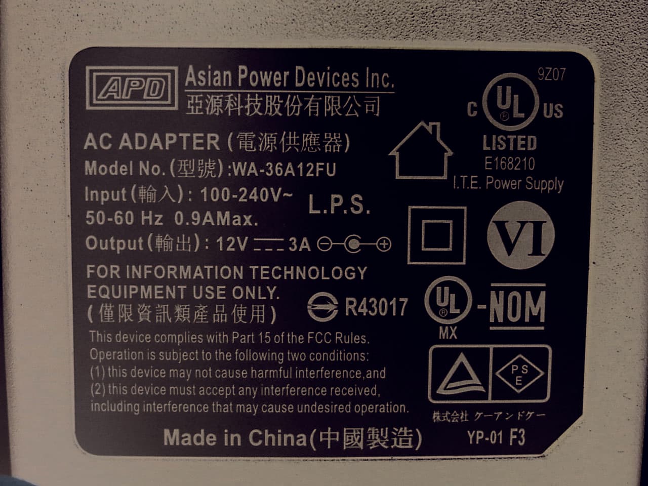
WL6-MPC
Nov 24, 2015Personal Computer
Equipment Class
DXX - Part 15 Low Power Communication Device Transmitter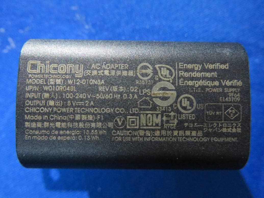
WL6-TE69SA3
Sep 22, 2015Tablet PC
Equipment Class
DSS - Part 15 Spread Spectrum Transmitter