WL6-TE69SA3Tablet PC
ELITEGROUP COMPUTER SYSTEMS CO., LTD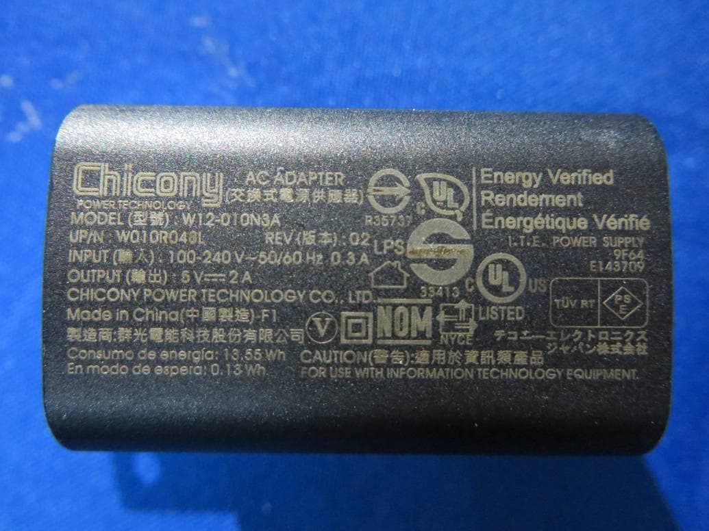
Click to zoom
Application Details
- Equipment Class
- DSS - Part 15 Spread Spectrum Transmitter
- Date of Grant
- Sep 22, 2015
- Application Purpose
- Original Equipment
- Date of Application
- Sep 22, 2015
- Equipment Note
- Tablet PC
- Frequency Range
- 2402.00000000 - 2480.00000000
- Country
- Taiwan
Documents & Files
Document Text
Text extracted from the exhibit documents filed with the FCC. Open a document above to read the original.
Users Manual
Tablet for Android TE69SA3 Quick Start Guide 1 Federal Communication Commission Interference Statement This equipment has been tested and found to comply with the limits for a Class B digital device, pursuant to Part 15 of the FCC Rules. These limits are designed to provide reasonable protection against harmful interference in a residential installation. This equipment generates, uses and can radiate radio frequency energy and, if not installed and used in accordance with the instructions, may cause harmful interference to radio communications. However, there is no guarantee that interference will not occur in a particular installation. If this equipment does cause harmful interference to radio or television reception, which can be determined by turning the equipment off and on, the user is encouraged to try to correct the interference by one of the following measures: - Reorient or relocate the receiving antenna. - Increase the separation between the equipment and receiver. - Connect the equipment into an outlet on a circuit different from that to which the receiver is connected. - Consult the dealer or an experienced radio/TV technician for help. Caution: Any changes or modifications not expressly approved by the party responsible for compliance could void the user's authority to operate this equipment. This device complies with Part 15 of the FCC Rules. Operation is subject to the following two conditions: (1) This device may not cause harmful interference, and (2) This device must accept any interference received, including interference that may cause undesired operation. 27 2 RF Exposure Information (SAR) This device meets the government’s requirements for exposure to radio waves. This device is designed and manufactured not to exceed the emission limits for exposure to radio frequency (RF) energy set by the Federal Communications Commission of the U.S. Government. The exposure standard employs a unit of measurement known as the Specific Absorption Rate, or SAR. The SAR limit set by the FCC is 1.6 W/kg. Tests for SAR are conducted using standard operating positions accepted by the FCC with the EUT transmitting at the specified power level in different channels. The highest SAR value for the device as reported to the FCC is 1. W/kg when placed next to the body. CAUTION Risk of explosion if battery is replaced by an incorrect type. Dispose of used batteries according to the instructions. ATTENTION RISQUE D'EXPLOSION SI LA BATTERIE EST REMPLACÉE PAR UN TYPE INCORRECT. RECYCLEZ LES BATTERIES USAGÉES SELON LES INSTRUCTIONS. Attention: Teachers, Parents and Adult Supervisors This product is an educational tool designed for school children, ages 6 and up. There must be supervision by an adult on school children under 10 when using this tablet. It is a must to have a thorough explanation to students on safe and proper handling of the tablet, power supply, battery pack, and power cord. 3 Be sure to keep the power cord away from younger children Please ensure that students understand the following: As with all electrical products, precautions should be observed during handling and use to prevent electric shock. The power supply (adapter) should not be handled by the children.” Emphasize to students that this device is an educational tool and not a toy. The tablet, power supply, battery pack or power cord should not be dropped, crushed, stepped on or otherwise abused. Ensure students understand the safe and proper handling of power cord and power supply. Misuse could result in serious injury. The teacher, parent or adult supervisor should periodically inspect the tablet; power supply and power cord for damage and replace it, if necessary. Students should report any damage or loose parts to their teacher, parents or adult supervisor, immediately. Do not leave the tablet plugged in or “on” when enclosed in a non-vented container, such as a school backpack, as overheating may occur. It is recommended that students should take a 5-minute break every 30 minutes of use. 4 Safety Precautions The following are lists of precautionary measure the students must understand before using this tablet inside the classroom or home environment: 1. Do not place near the fire or other sources of heat. 2. Do not expose to magnetic fields. 3. Do not expose to direct sunlight. 4. Do not expose to rain or moisture. 5. Do not place heavy objects to add heavy pressure on the tablet. 6. Do not drop the tablet. 5 Package contents Carefully unpack your box and take out the items listed below. If any of the items are missing or damaged, please contact your dealer immediately: • One tablet • One AC adapter • One USB cable • This guide 6 Tablet layout No. Name No. Name 1 Touchscreen 4 Volume up/down 2 Front facing camera 5 Microphone 3 Power lock button 7 No. Name No. Name 1 Rear facing camera 6 Micro SIM card slot 2 Power lock button 7 Speaker 3 Volume up/down 8 Micro USB 2.0 port 4 Micro SD card slot 9 Headphone jack 5 Micro SIM card slot 8 Charging your tablet If your tablet is just being unpacked from the box, you need to charge the tablet first. It will take around 4 to 5 hours to be fully charged. 1. Flip out the plug. 2. Take out the provided USB cable. Plug the USB head of the cable into the adapter. 3. Plug the micro-USB head of the cable - with the side marked with an icon facing up - into the micro-USB port on your tablet. Plug the adapter into a wall-socket. 9 Powering ON/OFF your tablet To power on your tablet Press and hold the power button down until the screen turn on. To power off your tablet To turn off your tablet, follow these steps: 1. Press and hold the Power Lock button. 2. Touch Power off from the menu as shown below.. 3. Touch OK to power down your tablet. 10 Inserting a storage card Your tablet supports micro-SD cards with maximum storage space up to 32G. You can insert the micro SD card and pull it out without powering down the tablet. To do so, follow the steps below. Install your Mi…
Text truncated - open the document above for the full version.
Cover Letter(s)
ELITEGROUP COMPUTER SYSTEMS CO., LTD No.239, Sec. 2, Ti Ding Blvd., Taipei, Taiwan --------------------------------------------------------------------------------------------------------------------- Date: 2015.09.18 Federal Communications Commission Authorization and Evaluation Division FCC ID: WL6-TE69SA3 Confidentiality Request Pursuant to Sections 0.457 and 0.459 of the Commission’s Rules, we hereby request confidential treatment of information accompanying this application as outlined below: 1. Block Diagram 2. Schematics 3. Operational Description 4. Parts List 5. Tune-up Procedure The above materials contain trade secrets and proprietary information not customarily released to the public. The public disclosure of these matters might be harmful to the applicant and provide unjustified benefits to its competitors. The applicant understands that pursuant to Rule 0.457, disclosure of this application and all accompanying documentation will not be made before the date of the Grant for this application. Sincerely, Name: WelanChen Position: Section Manager ELITEGROUP COMPUTER SYSTEMS CO., LTD
External Photos
(1) EUT Photo (2) EUT Photo (3) EUT Photo (4) EUT Photo (5) EUT Photo (6) EUT Photo (7) EUT Photo (8) EUT Photo (Adapter #1) (9) EUT Photo (Adapter #1) (10) EUT Photo (Adapter #2) (11) EUT Photo (Adapter #2)
ID Label/Location Info
Label Label Location
Internal Photos
(1) EUT Photo (2) EUT Photo (3) EUT Photo (4) EUT Photo (5) EUT Photo (6) EUT Photo (7) EUT Photo (8) EUT Photo (9) EUT Photo (10) EUT Photo (11) EUT Photo (12) EUT Photo (13) EUT Photo (14) EUT Photo
Test Report
Report No.: 1503RSU01803 FCC ID: WL6-TE69SA3 Page Number: 41 of 97 7.7. Band-edge Compliance Measurement 7.7.1. Test Limit The maximum permissible emission level is 20dBc. Any emissions were lying outside of the emission bandwidth and in authorized band edges to a field strength limit specified in Section 15.209 of the Title 47 CFR. 7.7.2. Test Procedure Used ANSI C63.10-2013 - Section 7.8.6 7.7.3. Test Setting 1. Span = wide enough to capture the peak level of the emission operating on the channel closest to the band edge, as well as any modulation products which fall outside of the authorized band of operation. 2. RBW ≥ 1% of spectrum analyzer display span 3. VBW ≥ RBW 4. Detector = peak 5. Sweep time = auto couple 6. Trace mode = max hold 7. Trace was allowed to stabilize Allow the trace to stabilize. Set the marker on the emission at the band edge, or on the highest modulation product outside of the band, if this level is greater than that at the band edge. Enable the marker-delta function, than use the marker-to-peak function to move the marker to the peak of the in-band emission. Report No.: 1503RSU01803 FCC ID: WL6-TE69SA3 Page Number: 42 of 97 7.7.4. Test Setup Report No.: 1503RSU01803 FCC ID: WL6-TE69SA3 Page Number: 43 of 97 7.7.5. Test Result Test Mode Channel No. Frequency (MHz) Limit Result DH5 00 2402 20dBc Pass DH5 78 2480 20dBc Pass 2DH5 00 2402 20dBc Pass 2DH5 78 2480 20dBc Pass 3DH5 00 2402 20dBc Pass 3DH5 78 2480 20dBc Pass DH5 Band-edge Compliance Channel 00 (2402MHz) Channel 78 (2480MHz) 2DH5 Band-edge Compliance Channel 00 (2402MHz) Channel 78 (2480MHz) Report No.: 1503RSU01803 FCC ID: WL6-TE69SA3 Page Number: 44 of 97 3DH5 Band-edge Compliance Channel 00 (2402MHz) Channel 78 (2480MHz) DH5 Operation Frequency Range of 20dB Bandwidth within Hopping Mode Channel 00 (2402MHz) Channel 78 (2480MHz) 2DH5 Operation Frequency Range of 20dB Bandwidth within Hopping Mode Channel 00 (2402MHz) Channel 78 (2480MHz) Report No.: 1503RSU01803 FCC ID: WL6-TE69SA3 Page Number: 45 of 97 3DH5 Operation Frequency Range of 20dB Bandwidth within Hopping Mode Channel 00 (2402MHz) Channel 78 (2480MHz) Report No.: 1503RSU01803 FCC ID: WL6-TE69SA3 Page Number: 46 of 97 7.8. Conducted Spurious Emissions Measurement 7.8.1. Test Limit In any 100 kHz bandwidth outside the frequency band in which the spread spectrum or digitally modulated intentional radiator is operating, the radio frequency power that is produced by the intentional radiator shall be at least 20 dB below that in the 100 kHz bandwidth within the band that contains the highest level of the desired power, based on either an RF conducted or a radiated measurement, provided the transmitter demonstrates compliance with the peak conducted or a radiated measurement, provided the transmitter demonstrates compliance with the peak conducted power limits. If the transmitter complies with the conducted power limits based on the use of RMS averaging over a time interval, the attenuation required under this paragraph shall be 30 dB instead of 20 dB. 7.8.2. Test Procedure Used ANSI C63.10-2013 - Section 7.8.8 7.8.3. Test Setting 1. Span = wide enough to capture the peak level of the in-band emission and all spurious emissions (e.g., harmonics) from the lowest frequency generated in the EUT up through the 10 th harmonic. Typically, several plots are required to cover this entire span. 2. RBW = 100 KHz 3. VBW ≥ RBW 4. Detector = peak 5. Sweep time = auto couple 6. Trace mode = max hold 7. Trace was allowed to stabilize Set the marker on the peak of any spurious emission recorded. The level displayed must comply with the limit specified in this section. Report No.: 1503RSU01803 FCC ID: WL6-TE69SA3 Page Number: 47 of 97 7.8.4. Test Setup Report No.: 1503RSU01803 FCC ID: WL6-TE69SA3 Page Number: 48 of 97 7.8.5. Test Result Test Mode Channel No. Frequency (MHz) Limit (MHz) Result DH5 00 2402 20dBc Pass DH5 39 2441 20dBc Pass DH5 78 2480 20dBc Pass 2DH5 00 2402 20dBc Pass 2DH5 39 2441 20dBc Pass 2DH5 78 2480 20dBc Pass 3DH5 00 2402 20dBc Pass 3DH5 39 2441 20dBc Pass 3DH5 78 2480 20dBc Pass DH5 Conducted Spurious Emissions Channel 00 (2402MHz) Channel 39 (2441MHz) Channel 78 (2480MHz) Report No.: 1503RSU01803 FCC ID: WL6-TE69SA3 Page Number: 49 of 97 2DH5 Conducted Spurious Emissions Channel 00 (2402MHz) Channel 39 (2441MHz) Channel 78 (2480MHz) Report No.: 1503RSU01803 FCC ID: WL6-TE69SA3 Page Number: 50 of 97 3DH5 Conducted Spurious Emissions Channel 00 (2402MHz) Channel 39 (2441MHz) Channel 78 (2480MHz) Report No.: 1503RSU01803 FCC ID: WL6-TE69SA3 Page Number: 51 of 97 7.9. Radiated Spurious Emission Measurement 7.9.1. Test Limit All out of band emissions appearing in a restricted band as specified in Section 15.205 of the Title 47 CFR must not exceed the limits shown in Table per Section 15.209. FCC Part 15 Subpart C Paragraph 15.209 Frequency [MHz] Field Strength [V/m] Measured Distance [Meters] 0.009 - 0.490 2400/F (kHz) 300 0.490 - 1.705 24000/F (kHz) 30 1.705 – 30 30 30 30 – 88 100 3 88 – 216 150 3 216 – 960 200 3 Above 960 500 3 7.9.2. Test Procedure Used ANSI C63.10-2013 - Section 6.10.5 7.9.3. Test Setting Peak Field Strength Measurements 1. Analyzer center frequency was set to the frequency of the radiated spurious emission of interest 2. RBW = as specified in Table 1 3. VBW = 3 * RBW 4. Detector = peak 5. Sweep time = auto couple 6. Trace mode = max hold 7. Trace was allowed to stabilize Report No.: 1503RSU01803 FCC ID: WL6-TE69SA3 Page Number: 52 of 97 Table 1 - RBW as a function of frequency Frequency RBW 9 ~ 150 kHz 200 ~ 300 Hz 0.15 ~ 30 MHz 9 ~ 10 kHz 30 ~ 1000 MHz 100 ~ 120 kHz > 1000 MHz 1 MHz Average Field Strength Measurements 1. Analyzer center frequency was set to the frequency of the radiated spurious emission of interest 2. RBW = 1MHz 3. VBW ≥ 1/T 4. De As an alternative, the instrument may be set to linear detector mode. Ensure that video filtering is applied in linear voltage domain (rather than in a log or dB domain). Some i…
Text truncated - open the document above for the full version.
Test Report
MRT Technology (Suzhou) Co., Ltd Report No.: 1503RSU01803 Phone: +86-512-66308358 Report Version: V01 Fax: +86-512-66308368 Issue Date: 09-18-2015 Web: www.mrt-cert.com FCC ID: WL6-TE69SA3 Page Number: 1 of 97 FCC ID: WL6-TE69SA3 APPLICANT: ELITEGROUP COMPUTER SYSTEMS CO., LTD Application Type: Certification Product: Tablet PC Model No.: TE69SA3 Brand Name: ECS ELITEGROUP FCC Classification: FCC Part 15 Spread Spectrum Transmitter(DSS) FCC Rule Part(s): Part 15.247 Test Procedure(s): ANSI C63.10-2013, DA 00-705 Test Date: Mar. 26 ~ Apr. 02, 2015 MEASUREMENT REPORT FCC PART 15.247 Bluetooth v3.0 + HS Reviewed By : ( Robin Wu ) Approved By : ( Marlin Chen ) The test results relate only to the samples tested. This equipment has been shown to be capable of compliance with the applicable technical standards as indicated in the measurement report and was tested in accordance with the measurement procedures specified in ANSI C63.10-2013 and DA 00-705. Test results reported herein relate only to the item(s) tested. The test report shall not be reproduced except in full without the written approval of MRT Technology (Suzhou) Co., Ltd. Report No.: 1503RSU01803 FCC ID: WL6-TE69SA3 Page Number: 2 of 97 Revision History Report No. Version Description Issue Date 1503RSU01803 Rev. 01 Initial report 09-18-2015 Report No.: 1503RSU01803 FCC ID: WL6-TE69SA3 Page Number: 3 of 97 CONTENTS Description Page 1. INTRODUCTION ..................................................................................................................... 7 1.1. Scope ........................................................................................................................... 7 1.2. MRT Test Location ....................................................................................................... 7 2. PRODUCT INFORMATION ..................................................................................................... 8 2.1. Equipment Description .................................................................................................. 8 2.2. Product Specification Subjective to this Report ............................................................. 9 2.3. Working Frequencies .................................................................................................. 10 2.4. Pseudorandom Frequency Hopping Sequence ............................................................ 11 2.5. Device Capabilities ...................................................................................................... 11 2.6. Test Configuration ....................................................................................................... 11 2.7. Test Software .............................................................................................................. 11 2.8. EMI Suppression Device(s)/Modifications .................................................................... 11 2.9. Labeling Requirements ............................................................................................... 12 3. DESCRIPTION OF TEST ...................................................................................................... 13 3.1. Evaluation Procedure ................................................................................................. 13 3.2. AC Line Conducted Emissions ................................................................................... 13 3.3. Radiated Emissions .................................................................................................... 14 4. ANTENNA REQUIREMENTS ................................................................................................ 15 5. TEST EQUIPMENT CALIBRATION DATE ............................................................................ 16 6. MEASUREMENT UNCERTAINTY ......................................................................................... 17 7. TEST RESULT ...................................................................................................................... 18 7.1. Summary .................................................................................................................... 18 7.2. 20dB Bandwidth Measurement ................................................................................... 19 7.2.1. Test Limit ................................................................................................................ 19 7.2.2. Test Procedure used ............................................................................................... 19 7.2.3. Test Setting ............................................................................................................. 19 7.2.4. Test Setup ............................................................................................................... 20 7.2.5. Test Result .............................................................................................................. 21 7.3. Output Power Measurement ....................................................................................... 24 7.3.1. Test Limit ................................................................................................................ 24 7.3.2. Test Procedure Used .............................................................................................. 24 7.3.3. Test Setting ............................................................................................................. 24 7.3.4. Test Setup ............................................................................................................... 25 Report No.: 1503RSU01803 FCC ID: WL6-TE69SA3 Page Number: 4 of 97 7.3.5. Test Result .............................................................................................................. 26 7.4. Carrier Frequency Separation Measurement .............................................................. 29 7.4.1. Test Limit ..........................................................…
Text truncated - open the document above for the full version.
Test Setup Photos
FCC Part15C Test Setup Photo Description: Front View of the Conducted Emission Test Setup for 0.15kHz ~ 30MHz Description: Back View of the Conducted Emission Test Setup for 0.15kHz ~ 30MHz Description: Radiated Emission Test Setup for 9kHz ~ 30MHz Description: Radiated Emission Test Setup for 30MHz ~ 1GHz Description: Radiated Emission Test Setup for 1GHz ~ 18GHz Description: Radiated Emission Test Setup for 18GHz ~ 40GHz
Contact Information
Applicant
Tommy Lee(Manager)
Test Firm
MRT Technology (Suzhou) Co., LtdWu Jian
[email protected]86-512-66308358
Technical Specifications
| # | Rule Parts | Frequency Range | Power Output |
|---|---|---|---|
| 1 | 15C | 2.40 GHz - 2.48 GHz | 3.80 mW |
Other Applications from ELITEGROUP COMPUTER SYSTEMS CO., LTD
WL6LIVA-Q1APLUS
Jul 20, 2021Ultra tiny PC
Equipment Class
DTS - Digital Transmission System
WL6LIVAM300-W
May 12, 2021Computer
Equipment Class
DSS - Part 15 Spread Spectrum Transmitter
WL6-NU509560D2W
Jan 06, 2021Notebook
Equipment Class
DTS - Digital Transmission System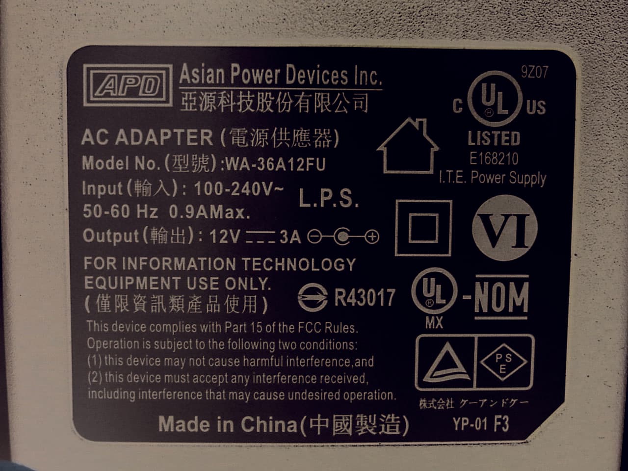
WL6-MPC
Nov 24, 2015Personal Computer
Equipment Class
DXX - Part 15 Low Power Communication Device Transmitter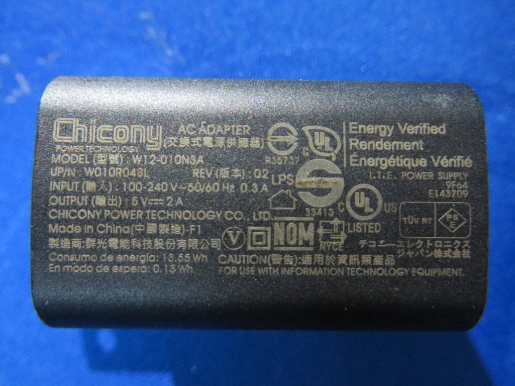
WL6-TC10RA3
May 14, 2015Tablet PC
Equipment Class
DSS - Part 15 Spread Spectrum Transmitter