WL6LIVA-Q1APLUSUltra tiny PC
ELITEGROUP COMPUTER SYSTEMS CO., LTD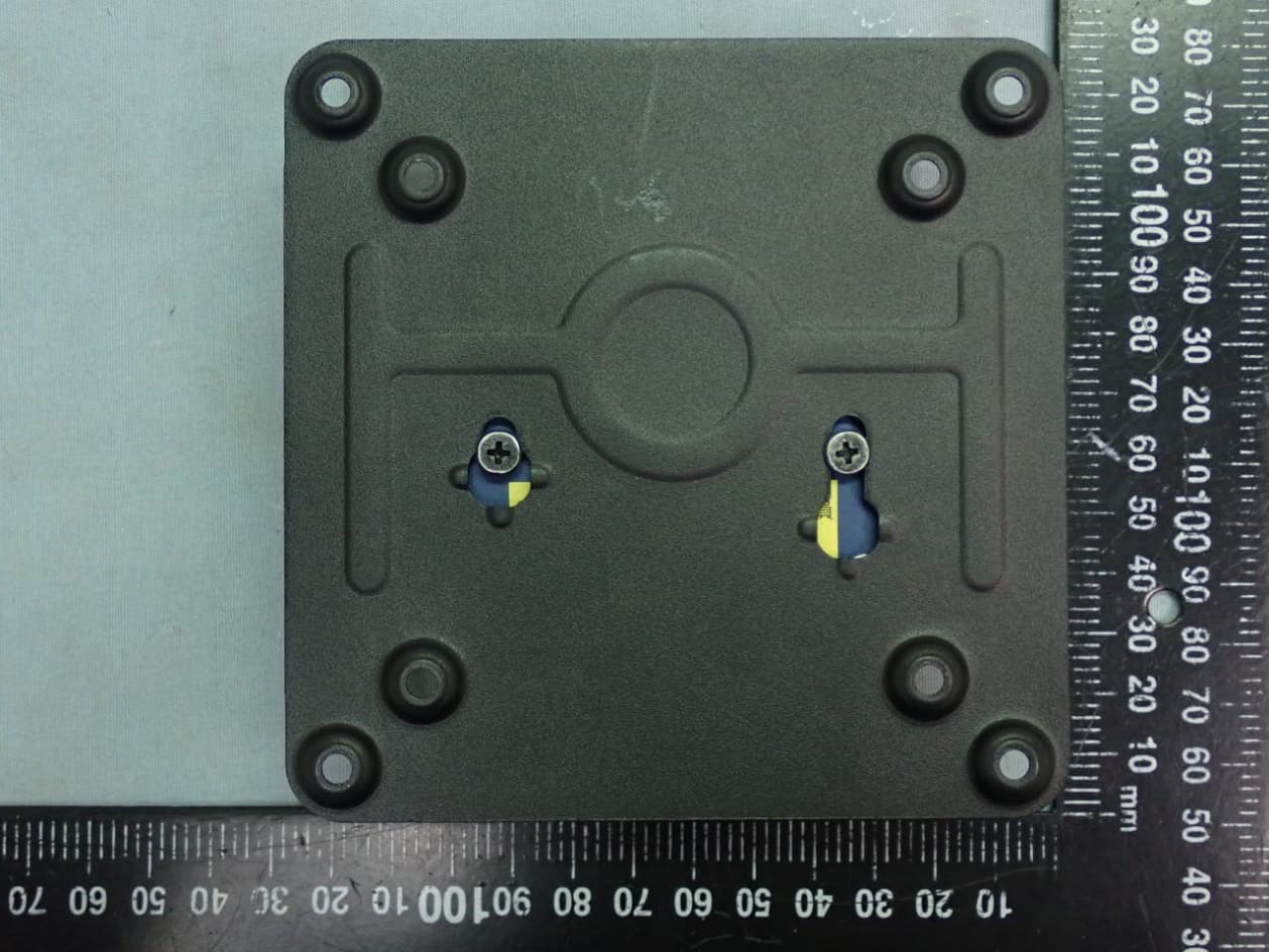
Click to zoom
Application Details
- Equipment Class
- DTS - Digital Transmission System
- Date of Grant
- Jul 20, 2021
- Application Purpose
- Original Equipment
- Date of Application
- Jul 20, 2021
- Equipment Note
- Ultra tiny PC
- Frequency Range
- 2412.00000000 - 2462.00000000
- Country
- Taiwan
Documents & Files
Document Text
Text extracted from the exhibit documents filed with the FCC. Open a document above to read the original.
Users Manual
Rockchip RK3288 TM 1 A/PB01A LIVA Q1A/ PB01A ULTRA TINY PC USER MANUAL i Preface Di sc l ai mer The information in this document is subject to change without notice. The manufacturer makes no representations or warranties with respect to the contents hereof and specifically disclaims any implied warranties of merchantability or fitness for any particular purpose. The manufacturer reserves the right to revise this publication and to make changes from time to time in the content hereof without obligation of the manufacturer to notify any person of such revision or changes. Tr ademar k Rec ogni ti on Rockchip is a registered trademark of Rockchip Electronics Co.,Ltd. Other product names used in this manual are the properties of their respective owners and are acknowledged. Copyr i ght This publication, including all photographs, illustrations and software, is protected under international copyright laws, with all rights reserved. Neither this manual, nor any of the material contained herein, may be reproduced without written consent of the author. Version 1.0 i i LIVA Q1A/ PB01A ULTRA TINY PC USER MANUAL Feder al Communi c ati ons Commi ssi on (FCC) This equipment has been tested and found to comply with the limits for a Class B digital device, pursuant to Part 15 of the FCC Rules. These limits are designed to provide reasonable protection against harmful interference in a residential installation. This equipment generates, uses, and can radiate radio frequency energy and, if not installed and used in accordance with the instructions, may cause harmful interference to radio communications. However, there is no guarantee that interference will not occur in a particular installation. If this equipment does cause harmful interference to radio or television reception, which can be determined by turning the equipment off and on, the user is encouraged to try to correct the interference by one or more of the following measures: Reorient or relocate the receiving antenna Increase the separation between the equipment and the receiver Connect the equipment onto an outlet on a circuit different from that to which the receiver is connected Consult the dealer or an experienced radio/TV technician for help Shielded interconnect cables and a shielded AC power cable must be employed with this equipment to ensure compliance with the pertinent RF emission limits governing this device. Changes or modifications not expressly approved by the system’s manufacturer could void the user’s authority to operate the equipment. LIVA Q1A/ PB01A ULTRA TINY PC USER MANUAL i i i Dec l ar ati on of Confor mi t y This device complies with part 15 of the FCC rules. Operation is subject to the following conditions: This device may not cause harmful interference. This device must accept any interference received, including interference that may cause undesired operation. Electromagnetic compatibility of multimedia equipment - Emission requirements EN 55032 EN 61000-3-2 Electromagnetic Compatibility(EMC) Part 3-2: Limits-Limits for harmonic current emissions (equipment input current 16A per phase) EN 61000-3-3 Electromagnetic Compatibility(EMC) Part 3-3: Limits-Limitation of voltage changes, voltage fluctuations and flicker in public low- voltage supply systems, for equipment with rated current 16A per phase and not subject to conditional connection EN 55024 Information technology equipment-Immunity characteristics-Limits and methods of measurement EN 60950 Safety for information technology equipment including electrical business equipment CE marking This device is in conformity with the following EC/EMC directives: EN 62368 Safety for information technology equipment including electrical business equipment i v LIVA Q1A/ PB01A ULTRA TINY PC USER MANUAL Safet y Instr uc ti ons Your system is designed and tested to meet the latest standards of safety for information technology equipment. However, to ensure your safety, it is important that you read the following safety instructions. Setti ng up your system Read and follow all instructions in the documentation before you operate your system. Do not use this product near water or a heated source such as a radiator. Set up the system on a stable surface. Openings on the chassis are for ventilation. Do not block or cover these openings. Make sure you leave plenty of space around the system for ventilation. Never insert objects of any kind into the ventilation openings. Use this product in environments with ambient temperatures between 0°C and 40°C. If you use an extension cord, make sure that the total ampere rating of the devices plugged into the extension cord does not exceed its ampere rating. Attenti on dur i ng use Do not step on the power cord or let anything rest on top of it. Do not spill water or any other liquid on your system. When the system is turned OFF, a small amount of electrical current still flows. Always unplug all power, modem, and network cables from the power outlets before cleaning the system. LIVA Q1A/ PB01A ULTRA TINY PC USER MANUAL v If you encounter the following technical problems with the product, unplug the power cord and contact a qualified service technician or your retailer. The power cord or plug is damaged. Liquid has been spilled into the system. The system does not function properly even if you follow the operating instructions. The system was dropped or the cabinet is damaged. The system performance changes. The warranty does not apply to products that have been disassembled by users. Safet y c auti ons and war ni ngs CAUTION: 1. To assure continued FCC compliance: Any changes or modifications not expressly approved by the grantee of this device could void the user’s authority to operate the equip- ment. 2. Exposure to Radio Frequency Radiation: This equipment complies with FCC radiation exposure limits forth for an uncontrolled environmrnt. This equipment should be installed and operated with minimum dis- tanc…
Text truncated - open the document above for the full version.
Cover Letter(s)
Declaration Letter Date: July 19, 2021 To whom it may concern: We have declared below features for FCC equipment authorization in regard to operating capability for FCC ID: WL6LIVA-Q1APLUS -- Product hardware has the capability to operate on channel 12 & 13. However, these 2 channels will be disabled via software and user will not able to enable these 2 channels. Sincerely, _________________________ Sunny Kuo Senior Manager Elitegroup Computer Systems Co., Ltd.
Cover Letter(s)
Family model declaration letter Date: July 19, 2021 FCC ID: WL6LIVA-Q1APLUS Product Description: Ultra tiny PC Model No.: (1)LIVA Q1AXXXXX (2)PB01AX (X=A to Z,a-z,0-9 or blank) The differences between above models are for marketing purpose. The details of differences description refer to below table 1. To whom it may concern: We hereby state that these models are identical in RF Spec, The differences of above models are as follows: Marketing Type (Appearance) Model Series Brand IO Board Mother Board CPU Resolution (Display) Type A LIVA Q1A LIVA AR3288-Q1AIO AR3288-Q1A RK3288 HDMI: 4090x2160/60Hz PB01A ECS Type B LIVA Q1A PLUS LIVA AR3399-Q1AIO AR3399-Q1A RK3399 HDMI: 4090x2160/60Hz DP: 2560x1440/60Hz PB01AP ECS Note: Marketing Type A and B used same WLAN Chip on IO Board, difference for some support IO ports and Layout. Sincerely, ___________________ Sunny Kuo Senior Manager Elitegroup Computer Systems Co., Ltd.
External Photos
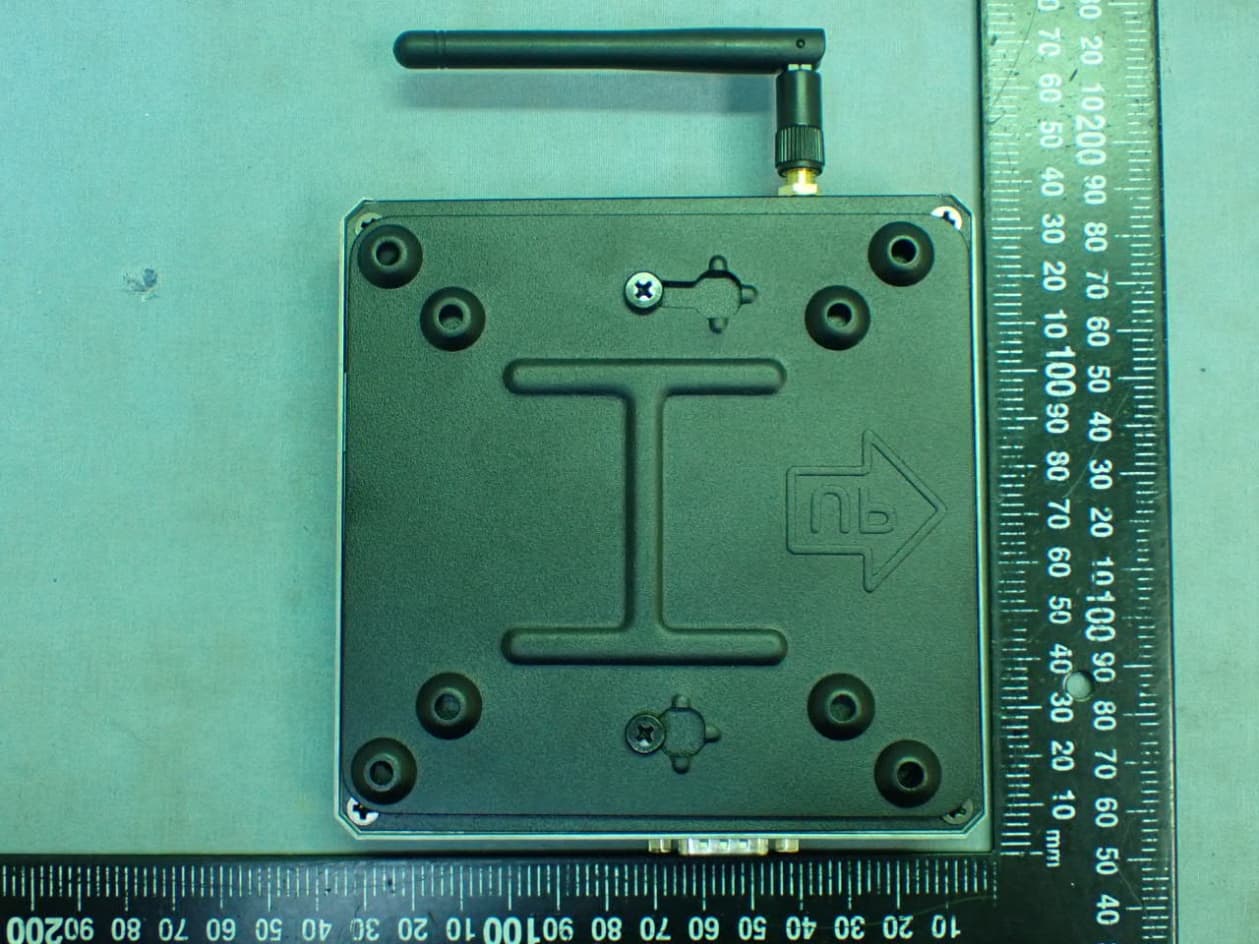
Elitegroup Computer Systems Co., Ltd. Ultra tiny PC FCC ID. : WL6LIVA-Q1APLUS EUT External Photos Marketing Type A, Test Model: LIVA Q1A Figure 1 General Appearance (Top View) (With VESA Mount) Figure 2 General Appearance (Bottom View) (With VESA Mount) Elitegroup Computer Systems Co., Ltd. Ultra tiny PC FCC ID. : WL6LIVA-Q1APLUS Figure 3 General Appearance (Top View) Figure 4 General Appearance (Bottom View) Elitegroup Computer Systems Co., Ltd. Ultra tiny PC FCC ID. : WL6LIVA-Q1APLUS Figure 5 General Appearance (Side View) Figure 6 General Appearance (Side View) Elitegroup Computer Systems Co., Ltd. Ultra tiny PC FCC ID. : WL6LIVA-Q1APLUS Figure 7 General Appearance (Side View) Figure 8 General Appearance (Side View) Elitegroup Computer Systems Co., Ltd. Ultra tiny PC FCC ID. : WL6LIVA-Q1APLUS Marketing Type B, Test Model: LIVA Q1A PLUS Figure 9 General Appearance (Top View) (With VESA Mount) Figure 10 General Appearance (Bottom View) (With VESA Mount) Elitegroup Computer Systems Co., Ltd. Ultra tiny PC FCC ID. : WL6LIVA-Q1APLUS Figure 11 General Appearance (Top View) Figure 12 General Appearance (Bottom View) Elitegroup Computer Systems Co., Ltd. Ultra tiny PC FCC ID. : WL6LIVA-Q1APLUS Figure 13 General Appearance (Side View) Figure 14 General Appearance (Side View) Elitegroup Computer Systems Co., Ltd. Ultra tiny PC FCC ID. : WL6LIVA-Q1APLUS Figure 15 General Appearance (Side View) Figure 16 General Appearance (Side View)
ID Label/Location Info
Elitegroup Computer Systems Co., Ltd. Ultra tiny PC FCC ID. : WL6LIVA-Q1APLUS FCC ID Label Location z FCC ID/IC Label Placement Location FCC ID Label Placement Location (EUT Bottom View) z FCC ID Label Format Elitegroup Computer Systems Co., Ltd. Ultra tiny PC Model : 17Z90N Series FCC ID Label Location z FCC ID/IC Label Placement Location FCC ID Label Placement Location (EUT Bottom View) z FCC ID Label Format
Internal Photos
Elitegroup Computer Systems Co., Ltd. Ultra tiny PC FCC ID. : WL6LIVA-Q1APLUS EUT Internal Photos Marketing Type A, Test Model: LIVA Q1A Figure 17 Internal View (Removed Cover) Figure 18 Internal View (Removed Cover) Elitegroup Computer Systems Co., Ltd. Ultra tiny PC FCC ID. : WL6LIVA-Q1APLUS Figure 19 Internal View Figure 20 Internal View (Removed Cover) Elitegroup Computer Systems Co., Ltd. Ultra tiny PC FCC ID. : WL6LIVA-Q1APLUS Figure 21 Mother Board, Front View Figure 22 Mother Board, Back View Elitegroup Computer Systems Co., Ltd. Ultra tiny PC FCC ID. : WL6LIVA-Q1APLUS Figure 23 I/O Board, Front View (RF Antenna Location) Figure 24 I/O Board, Back View Elitegroup Computer Systems Co., Ltd. Ultra tiny PC FCC ID. : WL6LIVA-Q1APLUS Figure 25 CPU View Figure 26 eMMC (Storage) View Elitegroup Computer Systems Co., Ltd. Ultra tiny PC FCC ID. : WL6LIVA-Q1APLUS Figure 27 DRAM View Figure 28 WLAN Combo View Elitegroup Computer Systems Co., Ltd. Ultra tiny PC FCC ID. : WL6LIVA-Q1APLUS Figure 29 WLAN Combo View (Removed Cover) Figure 30 WLAN Combo View (Back View) Elitegroup Computer Systems Co., Ltd. Ultra tiny PC FCC ID. : WL6LIVA-Q1APLUS Figure 31 RF Antenna Location Figure 32 RF Antenna Elitegroup Computer Systems Co., Ltd. Ultra tiny PC FCC ID. : WL6LIVA-Q1APLUS Marketing Type B, Test Model: LIVA Q1A PLUS Figure 33 Internal View (Removed Cover) Figure 34 Internal View (Removed Cover) Elitegroup Computer Systems Co., Ltd. Ultra tiny PC FCC ID. : WL6LIVA-Q1APLUS Figure 35 Internal View Figure 36 Internal View (Removed Cover) Elitegroup Computer Systems Co., Ltd. Ultra tiny PC FCC ID. : WL6LIVA-Q1APLUS Figure 37 Mother Board, Front View Figure 38 Mother Board, Back View Elitegroup Computer Systems Co., Ltd. Ultra tiny PC FCC ID. : WL6LIVA-Q1APLUS Figure 39 I/O Board, Front View (RF Antenna Location) Figure 40 I/O Board, Back View Elitegroup Computer Systems Co., Ltd. Ultra tiny PC FCC ID. : WL6LIVA-Q1APLUS Figure 41 CPU View Figure 42 eMMC (Storage) View Elitegroup Computer Systems Co., Ltd. Ultra tiny PC FCC ID. : WL6LIVA-Q1APLUS Figure 43 DRAM View Figure 44 WLAN Combo View Elitegroup Computer Systems Co., Ltd. Ultra tiny PC FCC ID. : WL6LIVA-Q1APLUS Figure 45 WLAN Combo View (Removed Cover) Figure 46 WLAN Combo View (Back View) Elitegroup Computer Systems Co., Ltd. Ultra tiny PC FCC ID. : WL6LIVA-Q1APLUS Figure 47 RF Antenna Location Figure 48 RF Antenna Location Elitegroup Computer Systems Co., Ltd. Ultra tiny PC FCC ID. : WL6LIVA-Q1APLUS Figure 49 AC Adapter, Front View Figure 50 AC Adapter, Back View Elitegroup Computer Systems Co., Ltd. Ultra tiny PC FCC ID. : WL6LIVA-Q1APLUS Figure 51 Adapter (Label View)
RF Exposure Info
Maximum Permissive Exposure FCC ID: WL6LIVA-Q1APLUS Product Description: Ultra tiny PC Model No: (1)LIVA Q1AXXXXX (2)PB01AX (X=A to Z,a-z,0-9 or blank) 1. According to FCC CFR 47 §1.1310, the criteria listed in the following table shall be used to evaluate the environmental impact of human exposure to radio frequency (RF) radiation as specified in 1.1307(b). Table 1 Limits for Maximum Permissible Exposure 2. MPE Calculation Elitegroup Computer Systems Co., Ltd. declares that the product described above has been evaluated and found to comply with the RF exposure limits for humans, as specified based on ANSI/FCC recommendation. Mode Max Output Power (dBm) Tune-up factor Tune-up max power (dBm) WIFI 2.4G 24.73 1.031 25.5 BT 9.57 1.097 10.5 BLE 6.63 1.131 7.5 **The value presented in the MPE is the maximum tune-up power. 2.1. WIFI 2.4G MPE Based on safety distance (r) 20cm , the antenna gain (G) is 1.524 Numerical, and the highest power output (P) is 354.81mW , the power density (S) is 0.107575mW/cm 2. RF Exposure Calculations: S = (P * G) / (4* π * r^2) or r = (P * G) / (4 * π * S) Where : Based on safety distance (r) = 20 cm Highest Power Output (P) = 25.5 dBm = 354.81 mW Antenna Gain (G) = 1.83 dBi = 1.524 Numerical MPE (S) = (P*G) / (4*π*r 2 ) = (354.81*1.524)/(4*π*20 2 ) = 0.107575 mW/cm 2 2.2. BT MPE Based on safety distance (r) 20cm , the antenna gain (G) is 1.524 Numerical, and the highest power output (P) is 11.22mW , the power density (S) is 0.003402mW/cm 2. RF Exposure Calculations: S = (P * G) / (4* π * r^2) or r = (P * G) / (4 * π * S) Where : Based on safety distance (r) = 20 cm Highest Power Output (P) = 10.5 dBm = 11.22 mW Antenna Gain (G) = 1.83 dBi = 1.524 Numerical MPE (S) = (P*G) / (4*π*r 2 ) = (11.22*1.524)/(4*π*20 2 ) = 0.003402 mW/cm 2 2.3. BLE MPE Based on safety distance (r) 20cm , the antenna gain (G) is 1.524 Numerical, and the highest power output (P) is 5.62mW , the power density (S) is 0.001704mW/cm 2. RF Exposure Calculations: S = (P * G) / (4* π * r^2) or r = (P * G) / (4 * π * S) Where : Based on safety distance (r) = 20 cm Highest Power Output (P) = 7.5 dBm = 5.62 mW Antenna Gain (G) = 1.83 dBi = 1.524 Numerical MPE (S) = (P*G) / (4*π*r 2 ) = (5.62*1.524)/(4*π*20 2 ) = 0.001704 mW/cm 2 2.4. Simultaneous Transmission WLAN 2.4G (mW/cm 2 ) BT (mW/cm 2 ) Total (mW/cm 2 ) 0.107575 0.003402 0.1110 Sincerely Yours, Mr. Johnny Hsueh Section Manager AUDIX Technology Corporation
Test Report
Page 1 of 32 Audix Technology Corp. Tel: +886 2 26099301 No. 491, Zhongfu Rd., Linkou Dist., Fax: +886 2 26099303 New Taipei City244,Taiwan File Number: C1M2103101 Report Number: EM-F210266 This test report may be reproduced in full only. The document may only be updated by Audix Technology Corp. personnel. Any changes will be noted in the Document History section of the report. FCC 15.247 2.4GHz Test Report for Elitegroup Computer Systems Co., Ltd. No. 239, Sec. 2., TiDing Blvd., Taipei, Taiwan 11493 Product Name : Ultra tiny PC Model Name : (1)LIVA Q1AXXXXX (2)PB01AX (X=A to Z,a-z,0-9 or blank) Brand : (1)LIVA (2)ECS FCC ID : WL6LIVA-Q1APLUS Prepared by: : AUDIX Technology Corporation, EMC Department The test report is based on a single evaluation of one sample of the above-mentioned products. It does notimply an assessment of the whole production and does not permit the use of the test lab logo. The report must not be used by the client to claim product certification, approval, or endorsement by NVLAP, NIST, or any agency of the U.S. Government. Page 2 of 32 Audix Technology Corp. Tel: +886 2 26099301 No. 491, Zhongfu Rd., Linkou Dist., Fax: +886 2 26099303 New Taipei City244,Taiwan File Number: C1M2103101 Report Number: EM-F210266 This test report may be reproduced in full only. The document may only be updated by Audix Technology Corp. personnel. Any changes will be noted in the Document History section of the report. TABLE OF CONTENTS Description Page TEST REPORT ................................................................................................................................... 4 1. REVISION RECORD OF TEST REPORT ............................................................................ 5 2. SUMMARY OF TEST RESULTS ........................................................................................... 6 3. GENERAL INFORMATION ................................................................................................... 7 3.1. Description of Application .............................................................................................................. 7 3.2. Description of EUT ......................................................................................................................... 8 3.3. Reference Test Guidance ................................................................................................................. 8 3.4. Antenna Information ....................................................................................................................... 9 3.5. EUT Specifications Assessed in Current Report ............................................................................. 9 3.6. Descriptions of Key Components .................................................................................................. 10 3.7. Test Configuration ......................................................................................................................... 11 3.8. Output Power Setting .................................................................................................................... 13 3.9. Tested Supporting System List ...................................................................................................... 14 3.10. Setup Configuration ....................................................................................................................... 15 3.11. Operating Condition of EUT ......................................................................................................... 15 3.12. Description of Test Facility ........................................................................................................... 16 3.13. Measurement Uncertainty ............................................................................................................. 17 4. MEASUREMENT EQUIPMENTLIST ................................................................................. 18 4.1. Conducted Emission Measurement ............................................................................................... 18 4.2. Radiated Emission Measurement .................................................................................................. 18 4.3. RF Conducted Measurement ......................................................................................................... 19 5. CONDUCTED EMISSION ..................................................................................................... 19 5.1. Block Diagram of Test Setup ........................................................................................................ 20 5.2. Conducted Emission Limit ............................................................................................................ 20 5.3. Test Procedure ............................................................................................................................... 20 5.4. Test Results ................................................................................................................................... 20 6. RADIATED EMISSION ......................................................................................................... 21 6.1. Block Diagram of Test Setup ........................................................................................................ 21 6.2. Radiated Emission Limits .............................................................................................................. 23 6.3. Test Procedure ............................................................................................................................... 24 6.4. Measurement Result Explanation .................................................................................................. 25 6.5. Test Results ................................................................................................................................... 25 7. 6dB/OCCUPIED BANDWIDTH .....................…
Text truncated - open the document above for the full version.
Test Setup Photos
APPENDIX B-Page 1 of 9 AUDIX Technology Corp. Tel: +886 2 26099301 No. 53-11, Dingfu, Linkou, Dist., Fax: +886 2 26099303 New Taipei City244, Taiwan File Number: C1M2103101 Report Number: EM-F210266 This test report may be reproduced in full only. The document may only be updated by Audix Technology Corp. personnel. Any changes will be noted in the Document History section of the report. B.1 Conducted Emission Measurement Test Model: LIVA Q1A FRONT VIEW BACK VIEW APPENDIX B-Page 2 of 9 AUDIX Technology Corp. Tel: +886 2 26099301 No. 53-11, Dingfu, Linkou, Dist., Fax: +886 2 26099303 New Taipei City244, Taiwan File Number: C1M2103101 Report Number: EM-F210266 This test report may be reproduced in full only. The document may only be updated by Audix Technology Corp. personnel. Any changes will be noted in the Document History section of the report. Test Model: LIVA Q1A Zoom View APPENDIX B-Page 3 of 9 AUDIX Technology Corp. Tel: +886 2 26099301 No. 53-11, Dingfu, Linkou, Dist., Fax: +886 2 26099303 New Taipei City244, Taiwan File Number: C1M2103101 Report Number: EM-F210266 This test report may be reproduced in full only. The document may only be updated by Audix Technology Corp. personnel. Any changes will be noted in the Document History section of the report. Test Model: LIVA Q1A PLUS FRONT VIEW BACK VIEW APPENDIX B-Page 4 of 9 AUDIX Technology Corp. Tel: +886 2 26099301 No. 53-11, Dingfu, Linkou, Dist., Fax: +886 2 26099303 New Taipei City244, Taiwan File Number: C1M2103101 Report Number: EM-F210266 This test report may be reproduced in full only. The document may only be updated by Audix Technology Corp. personnel. Any changes will be noted in the Document History section of the report. Test Model: LIVA Q1A Zoom View APPENDIX B-Page 5 of 9 AUDIX Technology Corp. Tel: +886 2 26099301 No. 53-11, Dingfu, Linkou, Dist., Fax: +886 2 26099303 New Taipei City244, Taiwan File Number: C1M2103101 Report Number: EM-F210266 This test report may be reproduced in full only. The document may only be updated by Audix Technology Corp. personnel. Any changes will be noted in the Document History section of the report. B.2 Radiated Measurement at Chamber Frequency Below to 1GHz Test Model: LIVA Q1A Zoom View APPENDIX B-Page 6 of 9 AUDIX Technology Corp. Tel: +886 2 26099301 No. 53-11, Dingfu, Linkou, Dist., Fax: +886 2 26099303 New Taipei City244, Taiwan File Number: C1M2103101 Report Number: EM-F210266 This test report may be reproduced in full only. The document may only be updated by Audix Technology Corp. personnel. Any changes will be noted in the Document History section of the report. Test Model: LIVA Q1A PLUS Zoom View APPENDIX B-Page 7 of 9 AUDIX Technology Corp. Tel: +886 2 26099301 No. 53-11, Dingfu, Linkou, Dist., Fax: +886 2 26099303 New Taipei City244, Taiwan File Number: C1M2103101 Report Number: EM-F210266 This test report may be reproduced in full only. The document may only be updated by Audix Technology Corp. personnel. Any changes will be noted in the Document History section of the report. Frequency Above to 1GHz Test Model: LIVA Q1A Zoom View APPENDIX B-Page 8 of 9 AUDIX Technology Corp. Tel: +886 2 26099301 No. 53-11, Dingfu, Linkou, Dist., Fax: +886 2 26099303 New Taipei City244, Taiwan File Number: C1M2103101 Report Number: EM-F210266 This test report may be reproduced in full only. The document may only be updated by Audix Technology Corp. personnel. Any changes will be noted in the Document History section of the report. Test Model: LIVA Q1A PLUS Zoom View APPENDIX B-Page 9 of 9 AUDIX Technology Corp. Tel: +886 2 26099301 No. 53-11, Dingfu, Linkou, Dist., Fax: +886 2 26099303 New Taipei City244, Taiwan File Number: C1M2103101 Report Number: EM-F210266 This test report may be reproduced in full only. The document may only be updated by Audix Technology Corp. personnel. Any changes will be noted in the Document History section of the report. B.3 RF Conducted Measurement
Contact Information
Applicant
Tommy Lee(Manager)
Technical Contact
AUDIX Technology CorporationBen Cheng
[email protected]+886226099301
No. 491, Zhongfu Rd., Linkou Dist. · New Taipei City · Taiwan
Test Firm
Audix Technology CorporationAllen Wang
Technical Specifications
| # | Rule Parts | Frequency Range | Power Output |
|---|---|---|---|
| 2 | 15C | 2.41 GHz - 2.46 GHz | 298.00 mW |
Other Applications from ELITEGROUP COMPUTER SYSTEMS CO., LTD
WL6LIVAM300-W
May 12, 2021Computer
Equipment Class
DSS - Part 15 Spread Spectrum Transmitter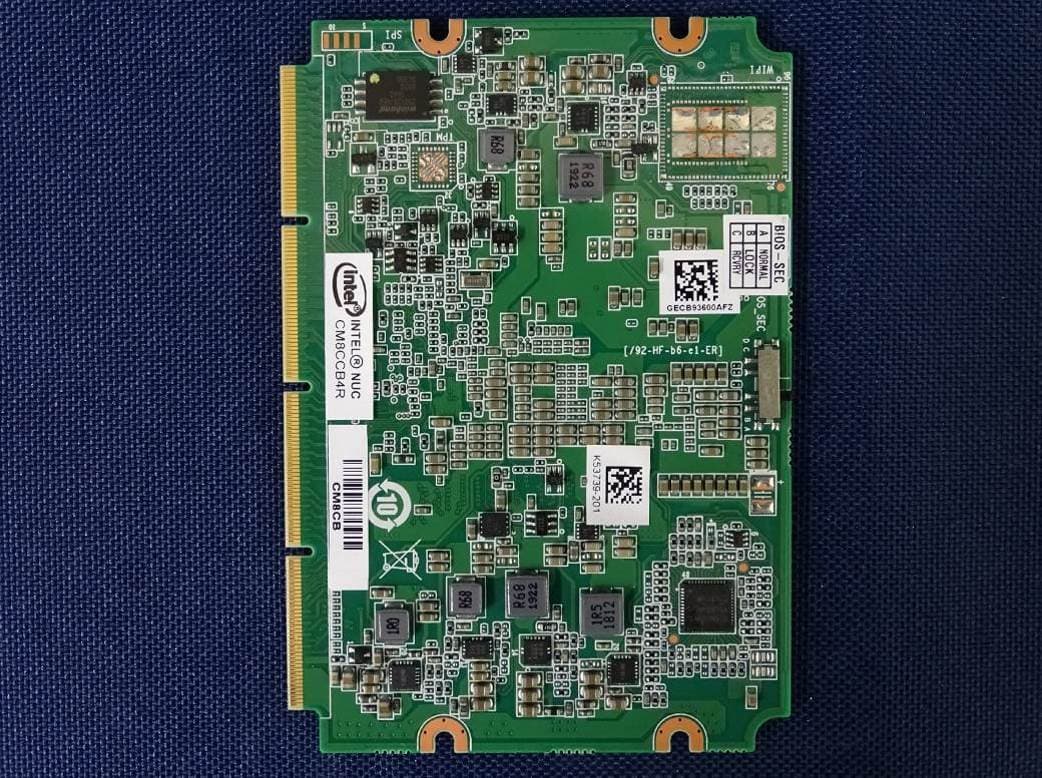
WL6-NU509560D2W
Jan 06, 2021Notebook
Equipment Class
DTS - Digital Transmission System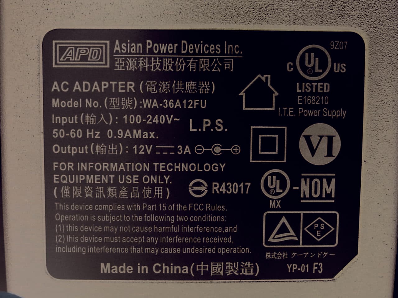
WL6-MPC
Nov 24, 2015Personal Computer
Equipment Class
DXX - Part 15 Low Power Communication Device Transmitter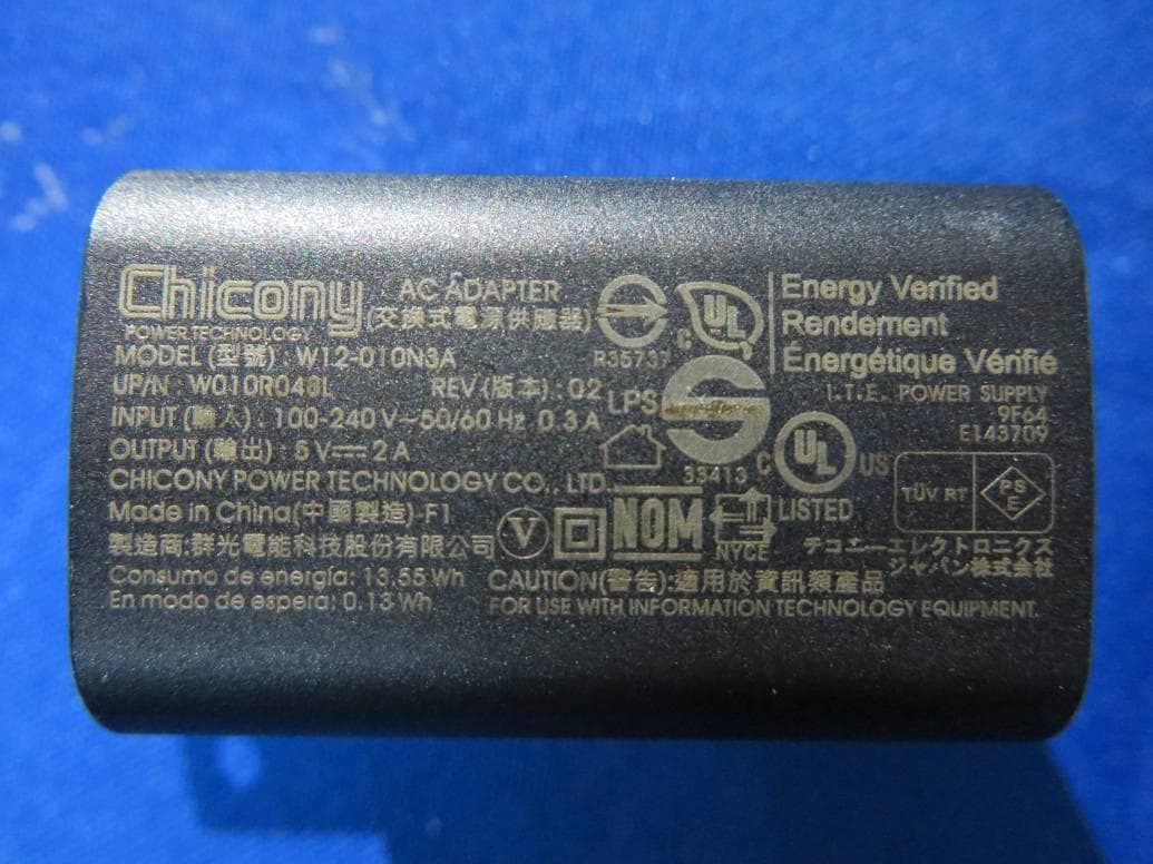
WL6-TE69SA3
Sep 22, 2015Tablet PC
Equipment Class
DSS - Part 15 Spread Spectrum Transmitter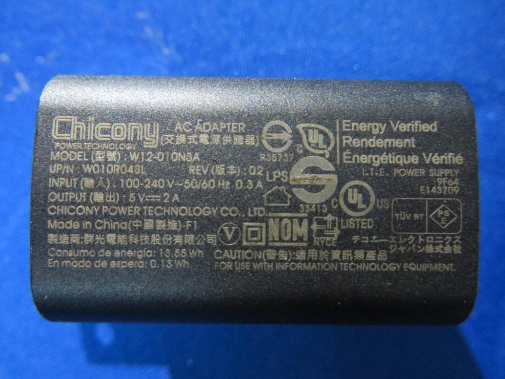
WL6-TC10RA3
May 14, 2015Tablet PC
Equipment Class
DSS - Part 15 Spread Spectrum Transmitter