WL6-TR10RS1AP6330Tablet PC
ELITEGROUP COMPUTER SYSTEMS CO., LTD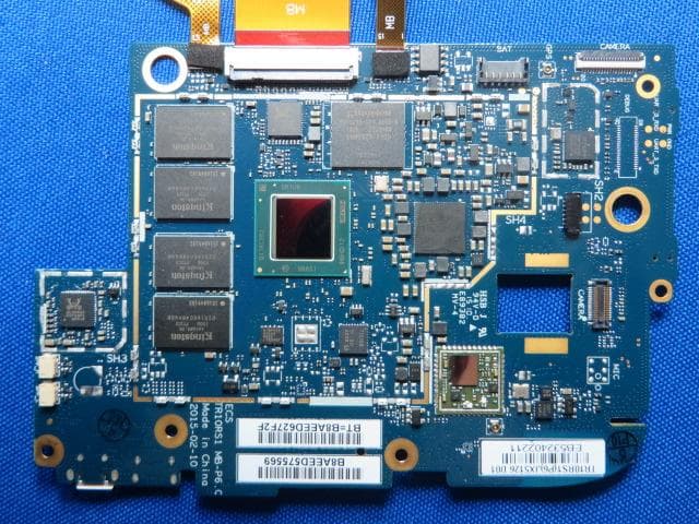
Click to zoom
Application Details
- Equipment Class
- NII - Unlicensed National Information Infrastructure TX
- Date of Grant
- Apr 07, 2015
- Application Purpose
- Original Equipment
- Date of Application
- Apr 06, 2015
- Equipment Note
- Tablet PC
- Frequency Range
- 5745.00000000 - 5825.00000000
- Country
- Taiwan
Documents & Files
Document Text
Text extracted from the exhibit documents filed with the FCC. Open a document above to read the original.
Users Manual
Quick Start Guide For Android Tablet TR10RS1 1 Federal Communication Commission Interference Statement This equipment has been tested and found to comply with the limits for a Class B digital device, pursuant to Part 15 of the FCC Rules. These limits are designed to provide reasonable protection against harmful interference in a residential installation. This equipment generates, uses and can radiate radio frequency energy and, if not installed and used in accordance with the instructions, may cause harmful interference to radio communications. However, there is no guarantee that interference will not occur in a particular installation. If this equipment does cause harmful interference to radio or television reception, which can be determined by turning the equipment off and on, the user is encouraged to try to correct the interference by one of the following measures: - Reorient or relocate the receiving antenna. - Increase the separation between the equipment and receiver. - Connect the equipment into an outlet on a circuit different from that to which the receiver is connected. - Consult the dealer or an experienced radio/TV technician for help. Caution: Any changes or modifications not expressly approved by the party responsible for compliance could void the user's authority to operate this equipment. This device complies with Part 15 of the FCC Rules. Operation is subject to the following two conditions: (1) This device may not cause harmful interference, and (2) This device must accept any interference received, including interference that may cause undesired operation 2 RF Exposure Information (SAR) This device meets the government’s requirements for exposure to radio waves. This device is designed and manufactured not to exceed the emission limits for exposure to radio frequency (RF) energy set by the Federal Communications Commission of the U.S. Government. The exposure standard employs a unit of measurement known as the Specific Absorption Rate, or SAR. The SAR limit set by the FCC is 1.6 W/kg. Tests for SAR are conducted using standard operating positions accepted by the FCC with the EUT transmitting at the specified power level in different channels. The highest SAR value for the device as reported to the FCC is 1.51 W/kg when placed next to the body. CAUTION Risk of explosion if battery is replaced by an incorrect type. Dispose of used batteries according to the instructions. ATTENTION Risqued'explosionsi la batterieestremplacée par un type incorrect. Recyclez les batteries usagéesselon les instructions. Attention: Teachers, Parents and Adult Supervisors This product is an educational tool designed for school children, ageing 6 and up. Children under 10 must be supervised when using this tablet. It is a must to have a thorough explanation to students on safe and proper handling of the tablet, power supply, battery pack, and power cord. 3 Be sure to keep the power cord away from younger children Please ensure that students understand the following: As with all electrical products, precautions should be observed during handling and use to prevent electric shock. The power supply (adapter) should not be handled by the children.” Emphasize to students that this device is an educational tool and not a toy. The computer, power supply, battery pack or power cord should not be dropped, crushed, stepped on or otherwise abused. Ensure students understand the safe and proper handling of power cord and power supply. Misuse could result in serious injury. The teacher, parent or adult supervisor should periodically inspect the computer; power supply and power cord for damage and replace it, if necessary. Students should report any damage or loosen parts to their teacher, parents or adult supervisor, immediately. Do not leave the tablet plugged in or “on” when enclosed in a non-vented container, such as a school backpack, as overheating may occur. It is recommended that students should take a 5 minute break every 30 minutes of use. Safety Precautions Following picture is a list of precautionary measure the students must understand before using this computer inside the classroom or home environment: 4 1. Do not place near the fire or other source of heat. 2. Do not expose the tablet into magnetic fields. 3. Do not expose the tablet under direct sunlight. 4. Do not expose the tablet to rain or moisture. 5. Do not place heavy objects to add heavy pressure on the tablet. 6. Do not drop the tablet. Package contents Carefully unpack your box and take out the items listed below. If any of the items are missing or damaged, please contact your dealer immediately: • One tablet • One AC adapter • One USB cable • One stylus • One magnifying lens • One sensor • This quick guide brochure 5 Tablet layout No. Name No. Name 1 Light sensor 5 Stylus slot 2 Front facing camera 6 I/O cabinet (See page 7 for details) 3 Microphone 7 Touchscreen 4 Charging indicator 6 No. Name No. Name 1 Power button 4 Volume up/down 2 Microphone 5 Speaker 3 Rear facing camera 6 Micro SIM card slot 1 3 4 55 6 2 7 No. Name No. Name 1 Headphone 4 Micro USB DC IN / Micro USB port 2 Micro SD card slot 5 Micro SIM card slot 3 Micro HDMI port 8 Charging your tablet If your tablet is just being unpacked from the box, you need to charge the tablet first. It will take around 4 to 5 hours to be fully charged. 1. Plug the USB head of the cable into the adapter. 2. Plug the micro-USB head of the cable- with the side marked with “B” or an icon facing down - into the micro-USB port on your tablet. 3. Plug the adapter into a wall-socket. 9 Powering ON/OFF your tablet To power on your tablet Press and hold the power button down until the screen turn on. To power off your tablet To turn off your tablet, follow these steps: 1. Press and hold the Power Lock button. 2. The Power-off menu appears as shown below. Touch Power off. 3. Touch OK to power down your tablet. 10 Inserting a storage card Your tablet supports micro-SD cards with m…
Text truncated - open the document above for the full version.
ID Label/Location Info
Label Label Location
Internal Photos
Internal Photo (1) EUT Photo (2) EUT Photo (3) EUT Photo (4) EUT Photo (5) EUT Photo (6) EUT Photo (7) EUT Photo (8) EUT Photo (9) EUT Photo (10) EUT Photo (11) EUT Photo (12) EUT Photo (13) EUT Photo (14) EUT Photo (15) EUT Photo (16) EUT Photo (17) EUT Photo
RF Exposure Info
FCC SAR Test Report Product Name : Tablet PC Model No. : TR10RS1 FCC ID : WL6-TR10RS1AP6330 Applicant : ELITEGROUP COMPUTER SYSTEMS CO., LTD Address : No.239, Sec. 2, Tiding Blvd., Neihu Dist, Taipei City 14, Taiwan (R.O.C) Date of Receipt : Apr. 03, 2015 Date of Test : Apr. 04, 2015 Issued Date : Apr. 05, 2015 Report No. : 1540164R-HP-US-P03V01 Report Version : V1.1 The test results relate only to the samples tested. The test report shall not be reproduced except in full without the written approval of QuieTek Corporation. Report No.: 1540164R-HP-US-P03V01 Page: 3 of 107 Laboratory Information We, QuieTek Corporation, are an independent EMC and safety consultancy that was established the whole facility in our laboratories. The test facility has been accredited/accepted(audited or listed) by the following related bodies in compliance with ISO 17025, EN 45001 and specified testing scope: The related certificate for our laboratories about the test site and management system can be downloaded from QuieTek Corporation’s Web Site :http://www.quietek.com/tw/ctg/cts/accreditations.htm The address and introduction of QuieTek Corporation’s laboratories can be founded in our Web site : http://www.quietek.com/ If you have any comments, Please don’t hesitate to contact us. Our contact information is as below: HsinChu Testing Laboratory : No.75-2, 3rd Lin, Wangye Keng, Yonghxing Tsuen, Qionglin Shiang, Hsinchu County 307, Taiwan, R.O.C. TEL:+886-3-592-8858 / FAX:+886-3-592-8859 E-Mail : [email protected] LinKou Testing Laboratory : No.5-22, Ruishukeng, Linkou Dist., New Taipei City 24451, Taiwan, R.O.C. TEL : 886-2-8601-3788 / FAX : 886-2-8601-3789 E-Mail : [email protected] Suzhou Testing Laboratory : No.99 Hongye Rd., Suzhou Industrial Park Loufeng Hi-Tech Development Zone., SuZhou, China TEL : +86-512-6251-5088 / FAX : 86-512-6251-5098 E-Mail : [email protected] Taiwan R.O.C. :BSMI, NCC Germany :TUV Rheinland Norway :Nemko, DNV USA :FCC Japan :VCCI China :CNAS Report No.: 1540164R-HP-US-P03V01 Page: 4 of 107 TABLE OF CONTENTS Description Page 1. General Information ................................................................................................. 7 1.1. EUT Description .................................................................................................. 7 1.2. Test Environment ................................................................................................. 8 1.3. EUT Antenna Locations ....................................................................................... 8 1.4. Simultaneous Transmission Configurations ......................................................... 9 1.5. Power Reduction for SAR .................................................................................... 9 1.6. Guidance Documents .......................................................................................... 9 2. SAR Measurement System .................................................................................... 10 2.1. DASY5 System Description ............................................................................... 10 2.1.1. Applications ................................................................................................... 11 2.1.2. Area Scans .................................................................................................... 11 2.1.3. Zoom Scan (Cube Scan Averaging) .............................................................. 11 2.1.4. Uncertainty of Inter-/Extrapolation and Averaging ......................................... 11 2.2. DASY5 E-Field Probe ........................................................................................ 12 2.2.1. Isotropic E-Field Probe Specification ............................................................. 12 2.3. Boundary Detection Unit and Probe Mounting Device ...................................... 13 2.4. DATA Acquisition Electronics (DAE) and Measurement Server ........................ 13 2.5. Robot ................................................................................................................. 14 2.6. Light Beam Unit ................................................................................................. 14 2.7. Device Holder .................................................................................................... 15 2.8. SAM Twin Phantom ........................................................................................... 15 3. Tissue Simulating Liquid ....................................................................................... 16 3.1. The composition of the tissue simulating liquid ................................................. 16 3.2. Tissue Calibration Result ................................................................................... 16 3.3. Tissue Dielectric Parameters for Head and Body Phantoms ............................. 17 4. SAR Measurement Procedure ............................................................................... 18 4.1. SAR System Validation ...................................................................................... 18 4.1.1. Validation Dipoles .......................................................................................... 18 4.1.2. Validation Result ............................................................................................ 18 4.2. SAR Measurement Procedure ........................................................................... 20 5. SAR Exposure Limits ............................................................................................. 21 6. Test Equipment List ................................................................................................ 22 Report No.: 1540164R-HP-US-P03V01 Page: 5 of 107 7. Measurement Uncertainty ...................................................................................... 26 8. Conducted Power Measurement .............................................................…
Text truncated - open the document above for the full version.
Test Report
MRT Technology (Suzhou) Co., Ltd Report No.: 1504RSU00402 Phone: +86-512-66308358 Report Version: V01 Fax: +86-512-66308368 Issue Date: 04-05-2015 Web: www.mrt-cert.com FCC ID: WL6-TR10RS1AP6330 Page Number: 1 of 130 FCC ID: WL6-TR10RS1AP6330 APPLICANT: ELITEGROUP COMPUTER SYSTEMS CO., LTD Application Type: Certification Product: Tablet PC Model No.: TR10RS1 Trademark: ECS ELITEGROUP FCC Classification: Unlicensed National Information Infrastructure (UNII) FCC Rule Part(s): Part 15.407 Test Procedure(s): ANSI C63.10-2009, KDB 789033 D02v01 Test Date: Apr. 03 ~ 04, 2015 MEASUREMENT REPORT FCC PART 15.407 WLAN 802.11a/n Reviewed By : ( Robin Wu ) Approved By : ( Marlin Chen ) The test results relate only to the samples tested. This equipment has been shown to be capable of compliance with the applicable technical standards as indicated in the measurement report and was tested in accordance with the measurement procedures specified in KDB 789033 D02v01. Test results reported herein relate only to the item(s) tested. The test report shall not be reproduced except in full without the written approval of MRT Technology (Suzhou) Co., Ltd. Report No.: 1504RSU00402 FCC ID: WL6-TR10RS1AP6330 Page Number: 2 of 130 Revision History Report No. Version Description Issue Date 1504RSU00402 Rev. 01 Initial report 04-05-2015 Report No.: 1504RSU00402 FCC ID: WL6-TR10RS1AP6330 Page Number: 3 of 130 CONTENTS Description Page §2.1033 General Information ............................................................................................................ 6 1. INTRODUCTION ........................................................................................................................ 7 1.1. Scope .............................................................................................................................. 7 1.2. MRT Test Location .......................................................................................................... 7 2. PRODUCT INFORMATION ........................................................................................................ 8 2.1. Equipment Description .................................................................................................... 8 2.2. Working Frequencies ...................................................................................................... 8 2.3. Test Mode ....................................................................................................................... 8 2.4. Test Software ................................................................................................................... 8 2.5. Device Capabilities .......................................................................................................... 9 2.6. Test Configuration ........................................................................................................... 9 2.7. EMI Suppression Device(s)/Modifications ....................................................................... 9 2.8. Labeling Requirements ................................................................................................. 10 3. DESCRIPTION OF TEST ......................................................................................................... 11 3.1. Evaluation Procedure .................................................................................................... 11 3.2. AC Line Conducted Emissions ...................................................................................... 11 3.3. Radiated Emissions ....................................................................................................... 12 4. ANTENNA REQUIREMENTS .................................................................................................. 13 5. TEST EQUIPMENT CALIBRATION DATE .............................................................................. 14 6. MEASUREMENT UNCERTAINTY ........................................................................................... 15 7. TEST RESULT ......................................................................................................................... 16 7.1. Summary ....................................................................................................................... 16 7.2. 26dB Bandwidth Measurement ..................................................................................... 18 7.2.1. Test Limit ....................................................................................................................... 18 7.2.2. Test Procedure used ..................................................................................................... 18 7.2.3. Test Setting .................................................................................................................... 18 7.2.4. Test Setup ..................................................................................................................... 18 7.2.5. Test Result ..................................................................................................................... 19 7.3. 6dB Bandwidth Measurement ....................................................................................... 24 7.3.1. Test Limit ....................................................................................................................... 24 7.3.2. Test Procedure used ..................................................................................................... 24 7.3.3. Test Setting .................................................................................................................... 24 Report No.: 1504RSU00402 FCC ID: WL6-TR10RS1AP6330 Page Number: 4 of 130 7.3.4. Test Setup ..................................................................................................................... 24 7.3.5. Test Result ...........................................................................................................…
Text truncated - open the document above for the full version.
Test Report
Report No.: 1504RSU00402 FCC ID: WL6-TR10RS1AP6330 Page Number: 41 of 130 7.7.4. Test Result Voltage (%) Power (VAC) Temp (°C) Frequency (Hz) Freq. Dev. (Hz) Deviation (%) 100% 120 + 20 (Ref) 5219998973 -6247 -0.00011967 5299996638 -8662 -0.00016343 5599990382 -15218 -0.00027175 5784993527 -12258 -0.00021189 - 30 5220025068 19848 0.00038023 5300019232 13932 0.00026287 5600022883 17283 0.00030863 5785025172 19387 0.00033513 - 20 5220042503 37283 0.00071423 5300031662 26362 0.00049740 5600025994 20394 0.00036418 5785002163 -3622 -0.00006261 - 10 5219994603 -10617 -0.00020339 5299994238 -11062 -0.00020872 5599995077 -10523 -0.00018791 5785016068 10283 0.00017775 0 5220016203 10983 0.00021040 5299994673 -10627 -0.00020051 5599994973 -10627 -0.00018977 5785016073 10288 0.00017784 + 10 5219994658 -10562 -0.00020234 5299994738 -10562 -0.00019928 5599989592 -16008 -0.00028586 5784995134 -10651 -0.00018411 + 20 5219993103 -12117 -0.00023213 5299995684 -9616 -0.00018143 5599990639 -14961 -0.00026716 5784990622 -15163 -0.00026211 + 30 5219994769 -10451 -0.00020021 5299992632 -12668 -0.00023902 5599995532 -10068 -0.00017979 5784995617 -10168 -0.00017576 + 40 5219994508 -10712 -0.00020521 Report No.: 1504RSU00402 FCC ID: WL6-TR10RS1AP6330 Page Number: 42 of 130 5299990243 -15057 -0.00028409 5599993344 -12256 -0.00021886 5785009017 3232 0.00005587 + 50 5219994552 -10668 -0.00020437 5299994743 -10557 -0.00019919 5599995152 -10448 -0.00018657 5784996168 -9617 -0.00016624 115% 138 + 20 5219994552 -10668 -0.00020437 5299995683 -9617 -0.00018145 5599996983 -8617 -0.00015388 5784997722 -8063 -0.00013938 85% 102 + 20 5219997258 -7962 -0.00015253 5299998218 -7082 -0.00013362 5599995898 -9702 -0.00017325 5784997016 -8769 -0.00015158 Report No.: 1504RSU00402 FCC ID: WL6-TR10RS1AP6330 Page Number: 43 of 130 7.8. Radiated Spurious Emission Measurement 7.8.1. Test Limit All out of band emissions appearing in a restricted band as specified in Section 15.205 of the Title 47 CFR must not exceed the limits shown in Table per Section 15.209. FCC Part 15 Subpart C Paragraph 15.209 Frequency [MHz] Field Strength [V/m] Measured Distance [Meters] 0.009 - 0.490 2400/F (kHz) 300 0.490 - 1.705 24000/F (kHz) 30 1.705 - 30 30 30 30 - 88 100 3 88 - 216 150 3 216 - 960 200 3 Above 960 500 3 7.8.2. Test Procedure Used KDB 789033 D02v01 - Section G 7.8.3. Test Setting Peak Measurements above 1GHz 1. Analyzer center frequency was set to the frequency of the radiated spurious emission of interest 2. RBW = 1MHz 3. VBW = 3MHz 4. Detector = peak 5. Sweep time = auto couple 6. Trace mode = max hold 7. Trace was allowed to stabilize Report No.: 1504RSU00402 FCC ID: WL6-TR10RS1AP6330 Page Number: 44 of 130 Quasi-Peak Measurements below 1GHz 1. Analyzer center frequency was set to the frequency of the radiated spurious emission of interest 2. Span was set greater than 1MHz 3. RBW = 120 kHz 4. Detector = CISPR quasi-peak 5. Sweep time = auto couple 6. Trace was allowed to stabilize Average Measurements above 1GHz (Method AD) 1. Analyzer center frequency was set to the frequency of the radiated spurious emission of interest 2. RBW = 1MHz 3. VBW = 3MHz 4. Detector = power average (RMS) 5. Number of measurement points = 1001 (Number of points must be > 2 x span/RBW) 6. Sweep time = auto 7. Trace was averaged over at 100 sweeps 7.8.4. Test Setup 9kHz ~ 30MHz Test Setup: Report No.: 1504RSU00402 FCC ID: WL6-TR10RS1AP6330 Page Number: 45 of 130 30MHz ~ 1GHz Test Setup: 1GHz ~18GHz Test Setup: 18GHz ~40GHz Test Setup: Report No.: 1504RSU00402 FCC ID: WL6-TR10RS1AP6330 Page Number: 46 of 130 7.8.5. Test Result Test Mode: 802.11a Test Site: AC1 Test Channel: 36 Test Engineer: Roy Cheng Remark: 1. Average measurement was not performed if peak level lower than average limit. 2. Other frequency was 20dB below limit line within 1-18GHz, there is not show in the report. Mark Frequency (MHz) Reading Level (dBμV) Factor (dB) Measure Level (dBμV/m) Limit (dBμV/m) Margin (dB) Detector Polarization 7265.4 36.7 7.9 44.6 74.0 -29.4 Peak Horizontal * 8652.2 36.5 8.8 45.3 88.2 -42.9 Peak Horizontal 11544.2 35.9 12.7 48.6 74.0 -25.4 Peak Horizontal * 13145.6 36.1 12.5 48.6 88.2 -39.6 Peak Horizontal 7652.3 36.9 8.0 44.9 74.0 -29.1 Peak Vertical * 8647.3 36.7 8.8 45.5 88.2 -42.7 Peak Vertical 11477.5 36.2 12.7 48.9 74.0 -25.1 Peak Vertical * 13185.3 36.8 12.6 49.4 88.2 -38.8 Peak Vertical Note 1: “*” is not in restricted band, its limit is -27dBm/MHz. At a distance of 3 meters, the field strength limit in dBμV/m can be determined by adding a “conversion” factor of 95.2dB to the EIRP limit of -27dBm/MHz to obtain the limit for out of band spurious emissions. Note 2: Measure Level (dBμV/m) = Reading Level (dBμV) + Factor (dB) Factor (dB) = Cable Loss (dB) + Antenna Factor (dB/m) - Pre_Amplifier Gain (dB) Report No.: 1504RSU00402 FCC ID: WL6-TR10RS1AP6330 Page Number: 47 of 130 Test Mode: 802.11a Test Site: AC1 Test Channel: 44 Test Engineer: Roy Cheng Remark: 1. Average measurement was not performed if peak level lower than average limit. 2. Other frequency was 20dB below limit line within 1-18GHz, there is not show in the report. Mark Frequency (MHz) Reading Level (dBμV) Factor (dB) Measure Level (dBμV/m) Limit (dBμV/m) Margin (dB) Detector Polarization 7268.1 36.3 8.0 44.3 74.0 -29.7 Peak Horizontal * 8691.5 36.6 9.0 45.6 88.2 -42.6 Peak Horizontal 11487.7 36.0 12.8 48.8 74.0 -25.2 Peak Horizontal * 13155.6 35.4 12.5 47.9 88.2 -40.3 Peak Horizontal 7265.3 35.0 7.9 42.9 74.0 -31.1 Peak Vertical * 8647.6 35.9 8.8 44.7 88.2 -43.5 Peak Vertical 11568.0 35.2 12.7 47.9 74.0 -26.1 Peak Vertical * 13145.0 35.1 12.5 47.6 88.2 -40.6 Peak Vertical Note 1: “*” is not in restricted band, its limit is -27dBm/MHz. At a distance of 3 meters, the field strength limit in dBμV/m can be determined by adding a “conversion” factor of 95.2dB to the EIRP limit of -27dBm/MHz to obtain the limit for out of band spurious emissions. Note 2: Measure Level (dBμV/m) = Reading Level (dBμV) + Facto…
Text truncated - open the document above for the full version.
Test Report
MRT Technology (Suzhou) Co., Ltd Report No.: 1504RSU00405 Phone: +86-512-66308358 Report Version: V02 Fax: +86-512-66308368 Issue Date: 04-07-2015 Web: www.mrt-cert.com FCC ID: WL6-TR10RS1AP6330 Page Number: 1 of 25 FCC ID: WL6-TR10RS1AP6330 APPLICANT: ELITEGROUP COMPUTER SYSTEMS CO., LTD Application Type: Certification Product: Tablet PC Model No.: TR10RS1 Brand Name: ECS ELITEGROUP FCC Classification: Unlicensed National Information Infrastructure (UNII) FCC Rule Part(s): Part 15.407(h)(2), KDB 905462 D02v01, KDB 905462 D03v01, KDB 905462 D04v01 Type of Device: Master Device Client Device without radar detection Client Device with radar detection Test Date: Apr. 03 ~ 04, 2015 DFS MEASUREMENT REPORT FCC PART 15.407 Reviewed By : ( Robin Wu ) Approved By : ( Marlin Chen ) The test results relate only to the samples tested. This equipment has been shown to be capable of compliance with the applicable technical standards as indicated in the measurement report and was tested in accordance with the measurement procedures specified in KDB 905462 D02v01. Test results reported herein relate only to the item(s) tested. The test report shall not be reproduced except in full without the written approval of MRT Technology (Suzhou) Co., Ltd. Report No.: 1504RSU00405 FCC ID: WL6-TR10RS1AP6330 Page Number: 2 of 25 Revision History Report No. Version Description Issue Date 1504RSU00405 Rev. 01 Initial report 04-05-2015 1504RSU00405 Rev. 02 Added the Non-Occupancy Period 04-07-2015 Report No.: 1504RSU00405 FCC ID: WL6-TR10RS1AP6330 Page Number: 3 of 25 CONTENTS Description Page Revision History ................................................................................................................................ 2 §2.1033 General Information ............................................................................................................ 4 1. INTRODUCTION ........................................................................................................................ 5 1.1. Scope .............................................................................................................................. 5 1.2. MRT Test Location .......................................................................................................... 5 2. PRODUCT INFORMATION ........................................................................................................ 6 2.1. Equipment Description .................................................................................................... 6 2.2. DFS Band Carrier Frequencies Operation ...................................................................... 6 2.3. Test Mode ....................................................................................................................... 6 3. DFS DETECTION THRESHOLDS AND RADAR TEST WAVEFORMS .................................... 7 3.1. Applicability ..................................................................................................................... 7 3.2. DFS Devices Requirements ............................................................................................ 8 3.3. DFS Detection Threshold Values .................................................................................... 9 3.4. Parameters of DFS Test Signals ................................................................................... 10 3.5. Conducted Test Setup ................................................................................................... 13 4. TEST EQUIPMENT CALIBRATION DATE .............................................................................. 14 5. TEST RESULT ......................................................................................................................... 15 5.1. Summary ....................................................................................................................... 15 5.2. Radar Waveform Calibration ......................................................................................... 16 5.2.1. Calibration Setup ........................................................................................................... 16 5.2.2. Calibration Procedure .................................................................................................... 16 5.2.3. Cablibration Result ........................................................................................................ 17 5.3. Channel Loading Test Result ........................................................................................ 21 5.4. In-Service Monitoring for Channel Move Time, Channel Closing Transmission Time and Non-Occupancy Period Measurement .......................................................................................... 22 5.4.1. Test Limit ....................................................................................................................... 22 5.4.2. Test Procedure Used ..................................................................................................... 22 5.4.3. Test Result ..................................................................................................................... 23 6. CONCLUSION .......................................................................................................................... 25 Report No.: 1504RSU00405 FCC ID: WL6-TR10RS1AP6330 Page Number: 4 of 25 §2.1033 General Information Applicant: ELITEGROUP COMPUTER SYSTEMS CO., LTD Applicant Address: No.239, Sec. 2, Tiding Blvd., Neihu Dist, Taipei City 14, Taiwan (R.O.C) Manufacturer: ELITEGROUP COMPUTER SYSTEMS CO., LTD Manufacturer Address: No.239, Sec. 2, Tiding Blvd., Neihu Dist, Taipei City 14, Ta…
Text truncated - open the document above for the full version.
Contact Information
Applicant
Tommy Lee(Manager)
Technical Contact
MRT Technology (Suzhou) Co., LtdRobin Wu
[email protected]86-512-66308358
D8 Building, Youxin Industrial Park, No.2 · Suzhou · China
Non-Technical Contact
MRT Technology (Suzhou) Co., LtdRobin Wu
[email protected]86-512-66308358
Test Firm
MRT Technology (Suzhou) Co., LtdWu Jian
[email protected]86-512-66308358
Technical Specifications
| # | Rule Parts | Frequency Range | Power Output |
|---|---|---|---|
| 4 | 15E | 5.75 GHz - 5.83 GHz | 21.00 mW |
Other Applications from ELITEGROUP COMPUTER SYSTEMS CO., LTD
WL6LIVA-Q1APLUS
Jul 20, 2021Ultra tiny PC
Equipment Class
DTS - Digital Transmission System
WL6LIVAM300-W
May 12, 2021Computer
Equipment Class
DSS - Part 15 Spread Spectrum Transmitter
WL6-NU509560D2W
Jan 06, 2021Notebook
Equipment Class
DTS - Digital Transmission System
WL6-MPC
Nov 24, 2015Personal Computer
Equipment Class
DXX - Part 15 Low Power Communication Device Transmitter
WL6-TE69SA3
Sep 22, 2015Tablet PC
Equipment Class
DSS - Part 15 Spread Spectrum Transmitter