WL6GWS-QXIntelligent Gateway
ELITEGROUP COMPUTER SYSTEMS CO., LTD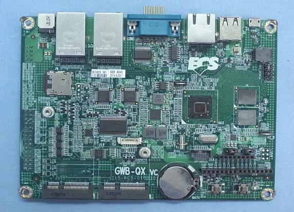
Click to zoom
Application Details
- Equipment Class
- DTS - Digital Transmission System
- Date of Grant
- Nov 26, 2014
- Application Purpose
- Original Equipment
- Date of Application
- Nov 26, 2014
- Equipment Note
- Intelligent Gateway
- Frequency Range
- 2402.00000000 - 2480.00000000
- Country
- Taiwan
Documents & Files
Document Text
Text extracted from the exhibit documents filed with the FCC. Open a document above to read the original.
Users Manual
Quick Manual Intelligent Gateway GWS-QX Copyright The documentation and the software included with this product are copyrighted 2014 by ECS Co., Ltd. All rights are reserved. ECS Co., Ltd. reserves the right to make improvements in the products described in this manual at any time without notice. No part of this manual may be reproduced, copied, translated or transmitted in any form or by any means without the prior written permission of ECS Co., Ltd. Information provided in this manual is intended to be accurate and reliable. However, ECS Co., Ltd. assumes no responsibility for its use, nor for any infringements of the rights of third parties, which may result from its use. Acknowledgements Intel® Quark SoC X1000 series are trademarks of Intel Corporation. McAfee* Embedded Control* and the Wind River* Intelligent Device Platform* All other product names or trademarks are properties of their respective owners. Declaration of Conformity FCC Class B Note: This equipment has been tested and found to comply with the limits for a Class B digital device, pursuant to part 15 of the FCC Rules. These limits are designed to provide reasonable protection against harmful interference in a residential installation. This equipment generates, uses and can radiate radio frequency energy and, if not installed and used in accordance with the instructions, may cause harmful interference to radio communications. However, there is no guarantee that interference will not occur in a particular installation. If this equipment does cause harmful interference to radio or television reception, which can be determined by turning the equipment off and on, the user is encouraged to try to correct the interference by one or more of the following measures: Reorient or relocate the receiving antenna. Increase the separation between the equipment and receiver. Connect the equipment into an outlet on a circuit different from that to which the receiver is connected. Consult the dealer or an experienced radio/TV technician for help. Part No. Edition 1 Printed in China Dec 2014 GWS-QX Intelligent Gateway ii FCC Label Compliance Statement: This device complies with Part 15 of the FCC Rules. Operation is subject to the following two conditions: (1) This device may not cause harmful interference (2) This device must accept any interference received, including interference that may cause undesired operation. Waste disposal instruction Do not throw this electronic device into the trash can when discarding. To minimize pollution and ensure utmost protection of the global environment, please recycle it in European WEEE (waste electrical and electronic equipment) directive system or recycle system in Taiwan. MPE警語 Exposure to Radio Frequency Radiation: To comply with FCC RF exposure compliance requirements, a separation distance of at least 20cm must be maintained between the antenna of this device and all persons. This device must not be co-located or operating in conjunction with any other antenna or transmitter. NCC警語 本產品符合低功率電波輻射性電機管理辦法 第十二條、第十四條等條文規定 1. 經型式認證合格之低功率射頻電機,非經許可,公司、商號或使用者均不得擅自變更頻率、加大功率或變更原設 計之特性及功能。 2. 低功率射頻電機之使用不得影響飛航安全及干擾合法通信;經發現有干擾現象時,應立即停用,並改善至無干擾 時方得繼續使用。 前項合法通信,指依電信法規定作業之無線電通信。 低功率射頻電機須忍受合法通信或工業、科學及醫療用電波輻射性電機設備之干擾。 電磁波曝露量MPE 標準值1mW/cm 2 ,送測產品實測值為:0.0941mW/cm 2 Caution! Danger of explosion if battery is incorrectly replaced. Replace only with the same or equivalent type recommended by the manufacturer. Dispose of used batteries according to the manufacturer's instructions Warning! Any changes or modifications made to the equipment which are not expressly approved by the relevant standards authority could void your authority to operate the equipment. Attention! Toute modification apportée à l'équipement qui n'est pas expressément approuvé par l'autorité des normes pertinentes peuvent annuler votre droit à faire fonctionner l'équipement. Attention! Danger d'explosion si la pile est remplacée de façon incorrecte. Remplacez-la uniquement avec le même type ou équivalent recommandé par le fabricant. Jetez les piles usagées selon les instructions du fabricant Part No. Edition 1 Printed in China Dec 2014 GWS-QX Intelligent Gateway Packing List Before setting up the system, check that the items listed below are included and in good condition. If any items are missing, please contact your dealer immediately. GWS-QX x1 Adapter x1 Power Cord x1 User Manual x1 USB to RS-232 cable x1 (Optional) Null Cable (RS-232) x1 (Optional) Antenna x2 (Optional) VESA Mount Bracket x1 (Optional) Warning! To prevent electric shock, Do not remove cover. No user serviceable parts inside, refer servicing to qualified personnel. Additional Information and Assistance 1. Visit the ECS websites at www.ECS.com.tw where you can find the latest information about the product. 2. Contact your distributor, sales representative, or ECS's customer service center for technical support if you need additional assistance. Please have the following information ready before you call: - Product name and serial number - Description of your peripheral attachments - Description of your software (operating system, version, application software, etc.) - A complete description of the problem - The exact wording of any error messages - This equipment is a source of electromagnetic waves. Before use, please make sure that there are not EMI sensitive devices in its surrounding which may malfunction therefore Warning! 1. Input voltage rated 100-240 VAC, 47-63 Hz, 2.0 A, Output Voltage rated 24 VDC, 5 A 2. Maintenance: to properly maintain and clean the surfaces, use only approved products or clean with a dry applicator iii GWS-QX Intelligent Gateway Attention! Pour éviter un choc électrique, ne pas retirer le couvercle. Aucune pièce réparable par l'utilisateur, voir l'entretien à du personnel qualifié. Attention! 1. Tension de sortie Tension d'entrée nominale 100-240 VAC, 47-63 Hz, 2,0 A, la note de 24 VDC, 5 A 2. Entretien: bien entretenir et net…
Text truncated - open the document above for the full version.
Cover Letter(s)
For the following information Ref. File No.: C1M1409210 Product Intelligent Gateway Model Number GWS-QX. Brand Name ECS Applicant Elitegroup Computer Systems Co., Ltd. Manufacturer Golden Elite Technology (SHENZHEN) CO., LTD. Standards FCC CFR 47 Part 15 Subpart B/Oct. 2013 and CISPR 22/1997 and ICES-003 (Class B Limit) We hereby certify that the above product has been tested by us and complied with the FCC and IC official limits. The product might be marketed in US in accordance with the standard CFR 47 Part 2 and Part 15 Subpart B class B equipment regulations under FCC Rules. The test was performed according to the procedures mentioned in ANSI C63.4-2009. The test data and results were issued on the test report no.EM-F140586. Signature _______________________ Ben Cheng/Manager Date: 2014. 10. 29 Test Laboratory: AUDIX Technology Corporation, EMC Department NVLAP Lab. Code: 200077-0 FCC OET Designation: TW1004 Web Site: www.audixtech.com The statement is based on a single evaluation of one sample of the above-mentioned products. It does not imply an assessment of the whole production and does not permit the use of the test lab logo.
External Photos
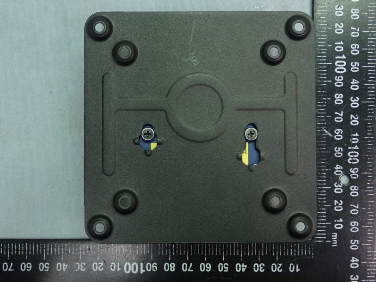
Elitegroup Computer Systems Co., Ltd. Intelligent Gateway FCC ID. : WL6GWS-QX EUT External Photos Figure 1 General Appearance (Top, Front and Side View) Figure 2 General Appearance (Bottom, Back and Side View) Antenna
ID Label/Location Info
Elitegroup Computer Systems Co., Ltd. Intelligent Gateway FCC ID. : WL6GWS-QX FCC ID Label Location z Label Placement Location GWS-QX z FCC ID Format ID Label Placement Location
Internal Photos
Elitegroup Computer Systems Co., Ltd. Intelligent Gateway FCC ID. : WL6GWS-QX EUT Internal Photos Figure 3 Internal View (Removed Antenna) Figure 4 Internal View (Removed Cover) Elitegroup Computer Systems Co., Ltd. Intelligent Gateway FCC ID. : WL6GWS-QX Figure 5 Internal View Figure 6 Internal View Elitegroup Computer Systems Co., Ltd. Intelligent Gateway FCC ID. : WL6GWS-QX Figure 7 Internal View Figure 8 Internal View Elitegroup Computer Systems Co., Ltd. Intelligent Gateway FCC ID. : WL6GWS-QX Figure 9 Internal View (Main Board, Front View) Figure 10 Internal View (Main Board, Back View) Elitegroup Computer Systems Co., Ltd. Intelligent Gateway FCC ID. : WL6GWS-QX Figure 11 Internal View (RF Board, Front View) Figure 12 Internal View (RF Board, Back View) Elitegroup Computer Systems Co., Ltd. Intelligent Gateway FCC ID. : WL6GWS-QX Figure 13 Internal View (RF Board, Removed Cover, Front View) Figure 14 Internal View (RF Board, Removed Cover, Back View) Elitegroup Computer Systems Co., Ltd. Intelligent Gateway FCC ID. : WL6GWS-QX Figure 15 Internal View (Internal Board, Front View) Figure 16 Internal View (Internal Board, Back View) Elitegroup Computer Systems Co., Ltd. Intelligent Gateway FCC ID. : WL6GWS-QX Figure 17 AC Adapter (Front and Side View) Figure 18 AC Adapter (Back and Side View) Elitegroup Computer Systems Co., Ltd. Intelligent Gateway FCC ID. : WL6GWS-QX Figure 19 AC Adapter (Label View) Figure 20 RS-232 Cable
RF Exposure Info
Maximum Permissive Exposure FCC ID: WL6GWS-QX Product Name: Intelligent Gateway Model No: GWS-QX. 1. According to FCC CFR 47 §1.1310, the criteria listed in the following table shall be used to evaluate the environmental impact of human exposure to radio frequency (RF) radiation as specified in 1.1307(b). Table 1 Limits for Maximum Permissible Exposure 2. MPE Calculation 2.1. WIFI MPE Elitegroup Computer Systems Co., Ltd. declares that the product described above has been evaluated and found to comply with the RF exposure limits for humans, as specified based on ANSI/FCC recommendation. Based on safety distance (r) 20cm, the antenna gain (G) is 2.042 Numerical, and the highest power output (P) is 231.739mW, the power density (S) is 0.094142mW/cm^2. RF Exposure Calculations: S = (P * G) / (4* * r^2) or r = (P * G) / (4 * * S) Where : Based on safety distance (r)= 20 cm Highest Power Output (P)= 23.65 dBm = 231.739mW Antenna Gain (G)= 3.1 dBi = 2.042Numerical MPE (S) = (P*G) / (4*π*r 2 ) = = (231.739*2.042)/(4*4*π*20 2 )= 0.094142 mW/cm 2 2.2. BLE MPE Elitegroup Computer Systems Co., Ltd. declares that the product described above has been evaluated and found to comply with the RF exposure limits for humans, as specified based on ANSI/FCC recommendation. Based on safety distance (r) 20cm, the antenna gain (G) is 2.042 Numerical, and the highest power output (P) is 4.842mW, the power density (S) is 0.001967mW/cm^2. RF Exposure Calculations: S = (P * G) / (4* * r^2) or r = (P * G) / (4 * * S) Where : Based on safety distance (r)= 20 cm Highest Power Output (P)= 6.85 dBm = 4.842mW Antenna Gain (G)= 3.1 dBi = 2.042Numerical MPE (S) = (P*G) / (4*π*r 2 ) = = (4.842*2.042)/(4*4*π*20 2 )= 0.001967 mW/cm 2 2.3. BT MPE Elitegroup Computer Systems Co., Ltd. declares that the product described above has been evaluated and found to comply with the RF exposure limits for humans, as specified based on ANSI/FCC recommendation. Based on safety distance (r) 20cm, the antenna gain (G) is 2.042 Numerical, and the highest power output (P) is 8.590mW, the power density (S) is 0.003490mW/cm^2. RF Exposure Calculations: S = (P * G) / (4* * r^2) or r = (P * G) / (4 * * S) Where : Based on safety distance (r)= 20 cm Highest Power Output (P)= 9.34 dBm = 8.590mW Antenna Gain (G)= 3.1 dBi = 2.042Numerical MPE (S) = (P*G) / (4*π*r 2 ) = = (8.590*2.042)/(4*4*π*20 2 )= 0.003490 mW/cm 2 MPE WIFI ( mW/cm 2 ) BLE ( mW/cm 2 ) BT ( mW/cm 2 ) Total( mW/cm 2 ) Limit ( mW/cm 2 ) 0.094142 0.001967 0.003490 0.099599 1 Sincerely Yours, ____________________________________ Mr. Ben Cheng Manager AUDIX Technology Corporation
Test Report
FCC ID: WL6GWS-QX Page 1 of 110 AUDIX Technology Corporation Report No. EM-F140584 APPLICATION FOR CERTIFICATION On Behalf of Elitegroup Computer Systems Co., Ltd. Intelligent Gateway Model No. : GWS-QX. FCC ID : WL6GWS-QX Brand: ECS Prepared for : Elitegroup Computer Systems Co., Ltd. No. 239, Sec. 2, TiDing Blvd, Taipei, Taiwan 11493 Prepared by : AUDIX Technology Corporation EMC Department No. 53-11, Dingfu, Linkou Dist., New Taipei City 244, Taiwan Tel : (02) 2609-9301, 2609-2133 Fax: (02) 2609-9303 File Number C1M1409210 Report Number EM-F140584 Date of Test 2014. 09. 24 ~ 11. 25 Date of Report 2014. 11. 25 FCC ID: WL6GWS-QX Page 2 of 110 AUDIX Technology Corporation Report No. EM-F140584 TABLE OF CONTENTS Description Page TEST REPORT CERTIFICATION ............................................................................................. 4 1. DESCRIPTION OF REVISION HISTORY .......................................................................... 5 2. GENERAL INFORMATION .................................................................................................. 6 2.1. Description of Device (EUT)........................................................................................................... 6 2.2. Description of Key Component Lists ..............................................................................................7 2.3. Data Rate Relative to Output Power................................................................................................ 8 2.4. Test Configuration for Each Test Item ............................................................................................ 9 2.5. Tested Supporting System Details ................................................................................................... 9 2.6. Description of Test Facility ........................................................................................................... 10 2.7. Measurement Uncertainty.............................................................................................................. 10 3. CONDUCTED EMISSION MEASUREMET...................................................................... 11 3.1. Test Equipments ............................................................................................................................ 11 3.2. Block Diagram of Test Setup......................................................................................................... 11 3.3. Powerline Conducted Emission Limit (§15.207)........................................................................... 11 3.4. Operating Condition of EUT ......................................................................................................... 12 3.5. Test Procedure ............................................................................................................................... 12 3.6. Conducted Emission Measurement Results................................................................................... 12 4. RADIATED EMISSION MEASUREMENT ....................................................................... 15 4.1. Test Equipments ............................................................................................................................ 15 4.2. Test Setup ...................................................................................................................................... 15 4.3. Radiated Emission Limits (§15.209) .............................................................................................17 4.4. Operating Condition of EUT ......................................................................................................... 17 4.5. Test Procedure ............................................................................................................................... 18 4.6. Test Results.................................................................................................................................... 19 5. 6dB BANDWIDTH MEASUREMENT ................................................................................ 52 5.1. Test Equipment .............................................................................................................................. 52 5.2. Block Diagram of Test Setup......................................................................................................... 52 5.3. Specification Limits [§15.247(a)(2)] ............................................................................................. 52 5.4. Operating Condition of EUT ......................................................................................................... 52 5.5. Test Procedure ............................................................................................................................... 52 5.6. Test Results.................................................................................................................................... 53 6. MAXIMUM PEAK OUTPUT POWER MEASUREMENT .............................................. 60 6.1. Test Equipments ............................................................................................................................ 60 6.2. Block Diagram of Test Setup......................................................................................................... 60 6.3. Specification Limits (§15.247(b)-(3))............................................................................................ 60 6.4. Operating Condition of EUT ......................................................................................................... 60 6.5. Test Procedure ............................................................................................................................... 60 6.6. Test Results.................................................................................................................................... 61 7. EMISSION LIMITATIONS MEASUREME…
Text truncated - open the document above for the full version.
Test Setup Photos
FCC ID: WL6GWS-QX Page 108 of 110 AUDIX Technology Corporation Report No. EM-F140584 11. PHOTOGRAPHS 11.1.Photos of Conducted Disturbance Measurement FRONT VIEW OF CONDUCTED MEASUREMENT BACK VIEW OF CONDUCTED MEASUREMENT FCC ID: WL6GWS-QX Page 109 of 110 AUDIX Technology Corporation Report No. EM-F140584 11.2.Photos of Radiated Measurement at Semi-Anechoic Chamber 11.2.1. Frequency Range 30MHz-1GHz 11.2.2. Frequency Range Above 1GHz FCC ID: WL6GWS-QX Page 110 of 110 AUDIX Technology Corporation Report No. EM-F140584 11.3.Photo of Section RF Conducted Measurement 11.4.Photo of Maximum Peak Output Power Measurement
Contact Information
Applicant
Tommy Lee(Manager)
Technical Contact
AUDIX Technology CorporationBen Cheng
[email protected]886 2609-9301
No. 53-11, Dingfu, Linkou Dist., · New Taipei City · Taiwan
Test Firm
Audix Technology CorporationJeff Chen
Technical Specifications
| # | Rule Parts | Frequency Range | Power Output |
|---|---|---|---|
| 2 | 15C | 2.40 GHz - 2.48 GHz | 4.84 mW |
Other Applications from ELITEGROUP COMPUTER SYSTEMS CO., LTD
WL6LIVA-Q1APLUS
Jul 20, 2021Ultra tiny PC
Equipment Class
DTS - Digital Transmission System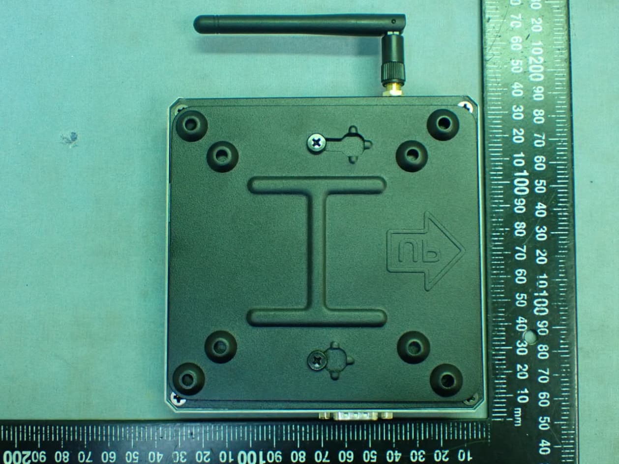
WL6LIVAM300-W
May 12, 2021Computer
Equipment Class
DSS - Part 15 Spread Spectrum Transmitter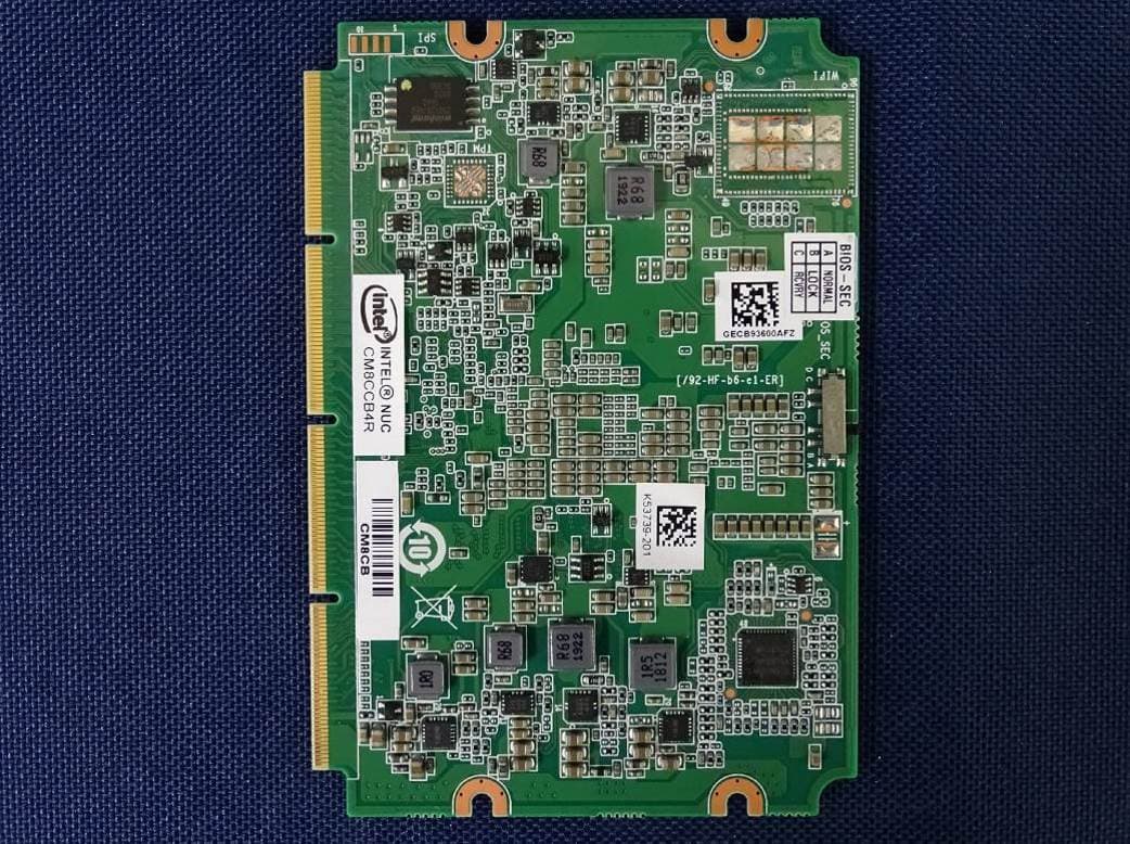
WL6-NU509560D2W
Jan 06, 2021Notebook
Equipment Class
DTS - Digital Transmission System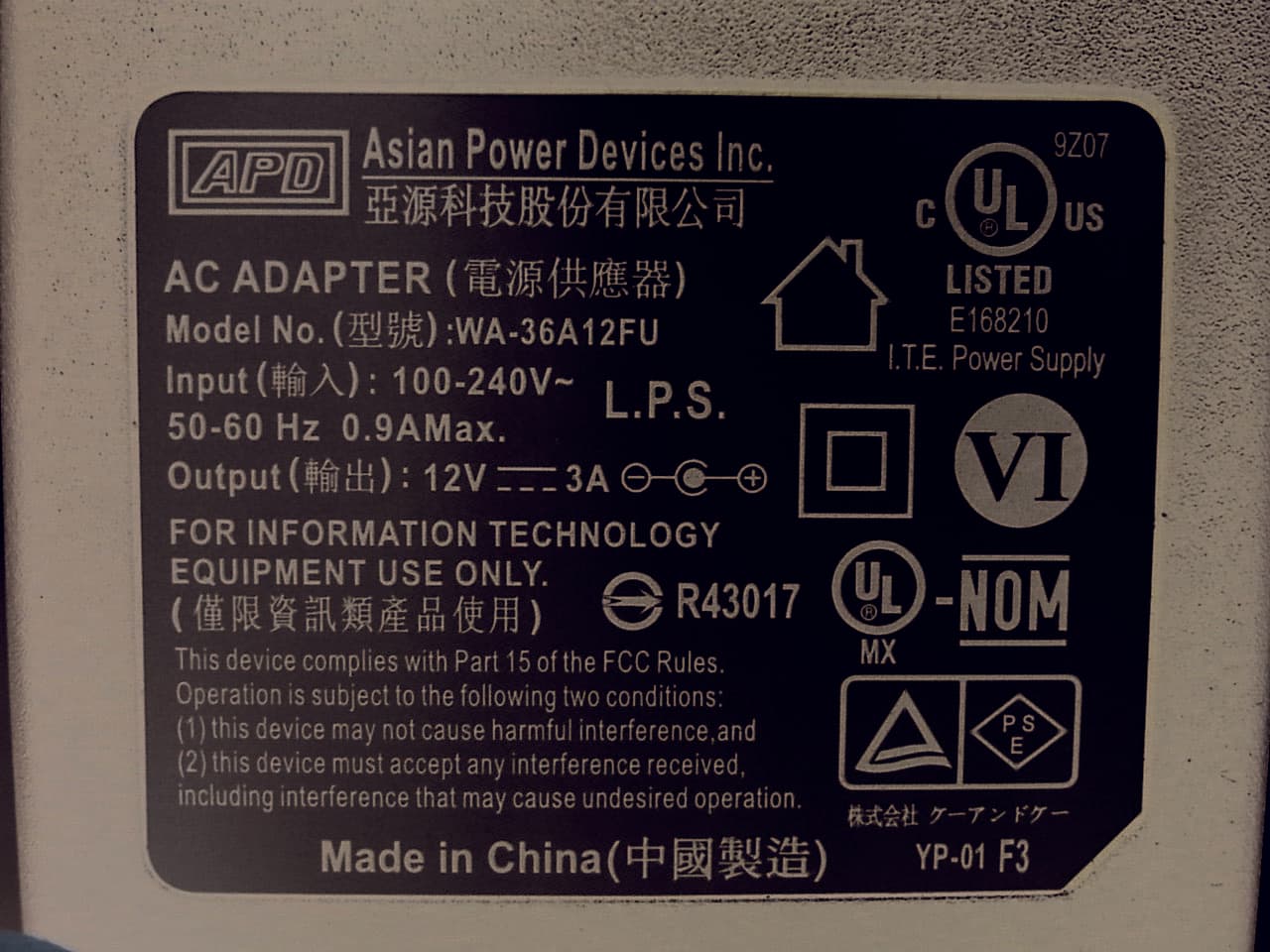
WL6-MPC
Nov 24, 2015Personal Computer
Equipment Class
DXX - Part 15 Low Power Communication Device Transmitter
WL6-TE69SA3
Sep 22, 2015Tablet PC
Equipment Class
DSS - Part 15 Spread Spectrum Transmitter