WL6TB71A-W7 Inch Pocketable Pad
ELITEGROUP COMPUTER SYSTEMS CO., LTD
Click to zoom
Application Details
- Equipment Class
- DXX - Part 15 Low Power Communication Device Transmitter
- Date of Grant
- Jun 28, 2014
- Application Purpose
- Original Equipment
- Date of Application
- Jun 26, 2014
- Equipment Note
- 7 Inch Pocketable Pad
- Frequency Range
- 13.56000000 - 13.56000000
- Country
- Taiwan
Documents & Files
Document Text
Text extracted from the exhibit documents filed with the FCC. Open a document above to read the original.
Users Manual
User Manual TB71A-W 7" Intel Atom based Pocketable pads Copyright The documentation and the software included with this product are copyrighted 2009 by ECS(ELITEGROUP COMPUTER SYSTEM) Co., Ltd. All rights are reserved. ECS Co., Ltd. reserves the right to make improvements in the products described in this manual at any time without notice. No part of this manual may be reproduced, copied, translated or transmitted in any form or by any means without the prior written permission of ECS Co., Ltd. Information provided in this manual is intended to be accurate and reliable. However, ECS Co., Ltd. assumes no responsibility for its use, nor for any infringements of the rights of third parties, which may result from its use. Acknowledgements Intel and Pentium are trademarks of Intel Corporation. Microsoft Windows and MS-DOS are registered trademarks of Microsoft Corp. All other product names or trademarks are properties of their respective owners. Declaration of Conformity FCC Class B Note: This equipment has been tested and found to comply with the limits for a Class B digital device, pursuant to part 15 of the FCC Rules. These limits are designed to provide reasonable protection against harmful interference in a residential installation. This equipment generates, uses and can radiate radio frequency energy and, if not installed and used in accordance with the instructions, may cause harmful interference to radio communications. However, there is no guarantee that interference will not occur in a particular installation. If this equipment does cause harmful interference to radio or television reception, which can be determined by turning the equipment off and on, the user is encouraged to try to correct the interference by one or more of the following measures: Reorient or relocate the receiving antenna. Increase the separation between the equipment and receiver. Connect the equipment into an outlet on a circuit different from that to which the receiver is connected. Consult the dealer or an experienced radio/TV technician for help. Part No. 2014050100 Edition 1 Printed in China May 2014 TB71A-W Tablet PC User Manual ii FCC Label Compliance Statement: This device complies with Part 15 of the FCC Rules. Operation is subject to the following two conditions: (1) this device may not cause harmful interference, and (2) this device must accept any interference received, including interference that may cause undesired operation. Caution! Danger of explosion if battery is incorrectly replaced. Replace only with the same or equivalent type recommended by the manufacturer. Dispose of used batteries according to the manufacturer's instructions Warning! Any changes or modifications made to the equipment which are not expressly approved by the relevant standards authority could void your authority to operate the equipment. Attention! Toute modification apportée à l'équipement qui n'est pas expressément approuvé par l'autorité des normes pertinentes peuvent annuler votre droit à faire fonctionner l'équipement. Attention! Danger d'explosion si la pile est remplacée de façon incorrecte. Remplacez-la uniquement avec le même type ou équivalent recommandé par le fabricant. Jetez les piles usagées selon les instructions du fabricant Packing List Before setting up the system, check that the items listed below are included and in good condition. If any items are missing, please contact your dealer immediately. TB71A-W x1 Strap x1 Stylus pen x1 USB Charger USB Charge Docking Cable x1 HDMI Docking cable x1 USB3.0 Docking cable x1 Docking Holder x1 Docking Power adapter x1 Software CD (Drivers and Utility, Manual) Warning! To prevent electric shock, Do not remove cover. No user serviceable parts inside, refer servicing to qualified personnel. Additional Information and Assistance 1. Visit the ECS websites at www.ecs.com.tw where you can find the latest information about the product. 2. Contact your distributor, sales representative, or ECS's customer service center for technical support if you need additional assistance. Please have the following information ready before you call: - Product name and serial number - Description of your peripheral attachments - Description of your software (operating system, version, application software, etc.) - A complete description of the problem - The exact wording of any error messages - This equipment is a source of electromagnetic waves. Before use, please make sure that there are not EMI sensitive devices in its surrounding which may malfunction therefore Warning! 1. Input voltage rated 100-240 VAC, 50-60 Hz, 1.5 A, Output Voltage rated 5 VDC, 2 A 2. Use a 3.7 V @ 4100 mA Lithium-ion battery (Model No. LWN436789) 3. Maintenance: to properly maintain and clean the surfaces, use only approved products or clean with a dry applicator iii TB71A-W Tablet PC User Manual Attention! Pour éviter un choc électrique, ne pas retirer le couvercle. Aucune pièce réparable par l'utilisateur, voir l'entretien à du personnel qualifié. Attention! 1. Tension de sortie Tension d'entrée nominale 100-240 VAC, 50- 60 Hz, 1,5 A, la note de 5 VDC, 2 A 2. Utiliser un V @ 4100 mA Batterie Lithium-ion (modèle n ° LWN436789) 3.7 3. Entretien: bien entretenir et nettoyer les surfaces, utiliser uniquement des produits approuvés ou nettoyer avec un applicateur sec Safety Instructions 1. Read these safety instructions carefully. 2. Keep this User Manual for later reference. 3. Disconnect this equipment from any AC outlet before cleaning. Use a damp cloth. Do not use liquid or spray detergents for cleaning. 4. For plug-in equipment, the power outlet socket must be located near the equipment and must be easily accessible. 5. Keep this equipment away from humidity. 6. Put this equipment on a reliable surface during installation. Dropping it or letting it fall may cause damage. 7. The openings on the enclosure are for air convection. Protect the equipment from overheating. DO NOT COVER TH…
Text truncated - open the document above for the full version.
Cover Letter(s)
THIS MUST BE SIGNED BY THE APPLICANT/AGENT AND SHOULD BE PLACED ON APPROPRIATE LETTERHEAD Request for Confidentiality Date: 2014/06/27 Subject: Confidentiality Request fo: WL6TB71A-W Pursuant to FCC 47 CRF 0.457(d) and 0.459 and IC RSP-100, Section 10, the applicant requests that a part of the subject FCC application be held confidential. Type of Confidentiality Requested Exhibit Shot Term Permanent Block Diagrams Shot Term External Photos Shot Term Permanent* 1 Internal Photos Shot Term Permanent Operation Description/Theory of Operation Shot Term Permanent Parts List & Placement/BOM Shot Term Permanent Tune-Up Procedure Shot Term Permanent Schematics Shot Term Test Setup Photos Shot Term Permanent* User’s Manual *Note: (Insert Explanation as Necessary) Elitegroup Computer Systems Co., Ltd. has spent substantial effort in developing this product and it is one of the first of its kind in industry. Having the subject information easily available to “competition” would negate the advantage they have achieved by developing this product. Not protecting the details of the design will result in financial hardship. Permanent Confidentiality: The applicant requests the exhibits listed above as permanently confidential be permanently withheld from public review due to materials that contain trade secrets and proprietary information not customarily released to the public. Short-Term Confidentiality: The applicant requests the exhibits selected above as short tern confidential be withheld from public view for a period of (specify number of days not to exceed 180) 2 days from the date of the Grant of Equipment Authorization and prior to marketing. This is to avoid premature release of sensitive information prior to marketing or release of the product to the public. Applicant is also aware that they are responsible to notify ACB in the event information regarding the product or the products is made available to the public. ACB will then release the documents listed above for public disclosure pursuant to FCC Public Notice DA 04-1705. NOTE for Industry Canada Applications: The applicant understands that until such time that IC distinguishes between Short Term and Permanent Confidentiality, either type of marked exhibit above will simply be marked Confidential when submitted to IC. Sincerely, By: Welan Chen ./ Section Manager (Signature/Title 3 ) (Print name) 1. -The asterisked items (*) require further justification before permanent confidentiality will be allowed. These also currently require review by the FCC under their Permit-But-Ask policy before the grant is issued and can delay completion of an application. Further justification should be added to the note above. One such example for a potted device would be: “The EUT is FULLY potted using a non-removable epoxy based material. Removal of potting material causes irreparable damage to internal circuitry. See photographs exhibits that outline the device before and after potting.” 2. –Please refer to http://acbcert.com.documents /misc-docs/Memo-Short-Term-Vs-Standard-Confidentiality.pdf for complete details. 3. –Must be signed by applicant contact given for applicant on the FCC site, or by the authorized agent if an appropriate authorized agent letter has been provided. Letters should be placed on appropriate letterhead.
Cover Letter(s)
For the following information Ref. File No.: C1S1404136 Product 7" Pocketable Pad Model Number (1)MICA-07......... (2)TABLET TB71...... Brand (1)ADVANTECH (2)ECS Applicant Elitegroup Computer Systems Co., Ltd. Manufacturer Elitegroup Computer Systems Co., Ltd. Standards FCC CFR 47 Part 15 Subpart B/ Oct. 2013 and CISPR 22/1997 (Class B Limit) We hereby certify that the above product has been tested by us and complied with the FCC and IC official limits. These products might be marketed at the US accordance to FCC Rule based on the standard CFR 47 Part 2 and Part 15 Class B Equipment Regulations. The test was performed accordance to the procedures from ANSI C63.4-2009. The test data & results are issued on the test report no. EM-F140281. Signature _____________________________ Ben Cheng/Manager Date: 2014. 05. 30 Test Laboratory: AUDIX Technology Corporation, EMC Department NVLAP Lab. Code: 200077-0 FCC OET Designation: TW1004 Web Site: www.audixtech.com The statement is based on a single evaluation of one sample of the above-mentioned products. It does not imply an assessment of the whole production and does not permit the use of the test lab logo. NVLAP Lab Code 200077-0
External Photos
Elitegroup Computer Systems Co., Ltd.7" Pocketable Pad FCC ID: WL6TB71A-W EUT External Photos Figure 1 General Appearance w/Docking (Front View) Figure 2 General Appearance w/Docking (Back View) Elitegroup Computer Systems Co., Ltd.7" Pocketable Pad FCC ID: WL6TB71A-W Figure 3 General Appearance w/Docking (Front View) Figure 4 General Appearance w/Docking (Rear View) Elitegroup Computer Systems Co., Ltd.7" Pocketable Pad FCC ID: WL6TB71A-W Figure 5 General Appearance w/Docking (Side View) Figure 6 General Appearance w/Docking (Side View) Elitegroup Computer Systems Co., Ltd.7" Pocketable Pad FCC ID: WL6TB71A-W Figure 7 General Appearance (Removed Docking) Figure 8 7" Pocketable Pad, General Appearance (Front View) Elitegroup Computer Systems Co., Ltd.7" Pocketable Pad FCC ID: WL6TB71A-W Figure 9 7" Pocketable Pad, General Appearance (Side View) Figure 10 7" Pocketable Pad, General Appearance (Side View) Elitegroup Computer Systems Co., Ltd.7" Pocketable Pad FCC ID: WL6TB71A-W Figure 11 7" Pocketable Pad, General Appearance (Side View) Figure 12 7" Pocketable Pad, General Appearance (Side View) Elitegroup Computer Systems Co., Ltd.7" Pocketable Pad FCC ID: WL6TB71A-W Figure 13 Stylus Pen View Figure 14 USB Charger, Appearance (Front & Side View) Elitegroup Computer Systems Co., Ltd.7" Pocketable Pad FCC ID: WL6TB71A-W Figure 15 USB Charger, Appearance (Back & Side View) Figure 16 USB Charger, Appearance (Product Label View) Elitegroup Computer Systems Co., Ltd.7" Pocketable Pad FCC ID: WL6TB71A-W Figure 17 USB Charger Cable Figure 18 Docking, General Appearance Elitegroup Computer Systems Co., Ltd.7" Pocketable Pad FCC ID: WL6TB71A-W Figure 19 Docking, General Appearance (Back & Side View) Figure 20 Docking, General Appearance (Bottom View) Elitegroup Computer Systems Co., Ltd.7" Pocketable Pad FCC ID: WL6TB71A-W Figure 21 Docking, General Appearance (Back View) Figure 22 Docking Power Adapter, Appearance (Front & Side View) Elitegroup Computer Systems Co., Ltd.7" Pocketable Pad FCC ID: WL6TB71A-W Figure 23 Docking Power Adapter, Appearance (Back & Side View) Figure 24 Docking Power Adapter, Appearance (Product Label View) Elitegroup Computer Systems Co., Ltd.7" Pocketable Pad FCC ID: WL6TB71A-W Figure 25 HDMI Docking Cable Figure 26 USB3.0 Docking Cable
ID Label/Location Info
Elitegroup Computer Systems Co., Ltd.7" Pocketable Pad FCC ID: WL6TB71A-W FCC ID Label Location z Label Placement Location z FCC ID Label Format FCC ID Label Placement Location
Internal Photos
Elitegroup Computer Systems Co., Ltd.7" Pocketable Pad FCC ID: WL6TB71A-W EUT Internal Photos Figure 27 7" Pocketable Pad, Internal View (Removed Back Cover) Figure 28 7" Pocketable Pad, Internal View (Removed Panel Frame) Elitegroup Computer Systems Co., Ltd.7" Pocketable Pad FCC ID: WL6TB71A-W Figure 29 7" Pocketable Pad, Internal View (Removed Main Board) Figure 30 7" Pocketable Pad, Internal View (Main Board, Back View) Elitegroup Computer Systems Co., Ltd.7" Pocketable Pad FCC ID: WL6TB71A-W Figure 31 7" Pocketable Pad, Internal View (Main Board, Front View) Figure 32 7" Pocketable Pad, Internal View (Barcode Scaner, Front View) Elitegroup Computer Systems Co., Ltd.7" Pocketable Pad FCC ID: WL6TB71A-W Figure 33 7" Pocketable Pad, Internal View (Barcode Scaner, Back View) Figure 34 7" Pocketable Pad, Internal View (Camera & Speaker, Front View) Elitegroup Computer Systems Co., Ltd.7" Pocketable Pad FCC ID: WL6TB71A-W Figure 35 7" Pocketable Pad, Internal View (Speaker, Back View) Figure 36 7" Pocketable Pad, Internal View (Removed Control Board, Main Board/Front View) Elitegroup Computer Systems Co., Ltd.7" Pocketable Pad FCC ID: WL6TB71A-W Figure 37 7" Pocketable Pad, Internal View (Control Board, Front View) Figure 38 7" Pocketable Pad, Internal View (Control Board, Back View) Elitegroup Computer Systems Co., Ltd.7" Pocketable Pad FCC ID: WL6TB71A-W Figure 39 7" Pocketable Pad, Internal View (WLAN+BT Module) Figure 40 7" Pocketable Pad, Internal View (WLAN+BT Module, Front View) Elitegroup Computer Systems Co., Ltd.7" Pocketable Pad FCC ID: WL6TB71A-W Figure 41 7" Pocketable Pad, Internal View (WLAN+BT Module, Back View) Figure 42 7" Pocketable Pad, Internal View (NFC Chip, Front View) Elitegroup Computer Systems Co., Ltd.7" Pocketable Pad FCC ID: WL6TB71A-W Figure 43 7" Pocketable Pad, Internal View (NFC Chip, Back View) Figure 44 7" Pocketable Pad, Internal View (GPS Module) Elitegroup Computer Systems Co., Ltd.7" Pocketable Pad FCC ID: WL6TB71A-W Figure 45 7" Pocketable Pad, Internal View (GPS Module, Front View) Figure 46 7" Pocketable Pad, Internal View (GPS Module, Back View) Elitegroup Computer Systems Co., Ltd.7" Pocketable Pad FCC ID: WL6TB71A-W Figure 47 7" Pocketable Pad, Internal View (Battery Pack View) Figure 48 7" Pocketable Pad, Internal View (Button Control Board, Front View) Elitegroup Computer Systems Co., Ltd.7" Pocketable Pad FCC ID: WL6TB71A-W Figure 49 7" Pocketable Pad, Internal View (Button Control Board, Back View) Figure 50 7" Pocketable Pad, Internal View (Frame of Panel) Elitegroup Computer Systems Co., Ltd.7" Pocketable Pad FCC ID: WL6TB71A-W Figure 51 7" Pocketable Pad, Internal View (Frame of Panel) Figure 52 7" Pocketable Pad, Internal View (Panel Label View) Elitegroup Computer Systems Co., Ltd.7" Pocketable Pad FCC ID: WL6TB71A-W Figure 53 7" Pocketable Pad, Internal View (Antenna View) Figure 54 7" Pocketable Pad, Internal View (Antenna View) Figure 55 Docking, Internal View (Removed Bottom Cover) WIFI AUX ANT WIFI MAIN ANT. GPS ANT. NFC ANT. Elitegroup Computer Systems Co., Ltd.7" Pocketable Pad FCC ID: WL6TB71A-W Figure 56 Docking, Internal View (Removed Main Board) Figure 57 Docking, Internal View (Main Board, Front View) Elitegroup Computer Systems Co., Ltd.7" Pocketable Pad FCC ID: WL6TB71A-W Figure 58 Docking, Internal View (Main Board, Back View) Figure 59 Docking, Internal View (Main Board Holder) Elitegroup Computer Systems Co., Ltd.7" Pocketable Pad FCC ID: WL6TB71A-W
Test Report
FCC ID. WL6TB71A-W Page 1 of 35 AUDIX Technology Corporation Report No. EM-F140299 APPLICATION FOR CERTIFICATION On Behalf of Elitegroup Computer Systems Co., Ltd. 7" Pocketable Pad Models No.: (1)MICA-07......... (2)TABLET TB71...... FCC ID: WL6TB71A-W Brand: (1)ADVANTECH (2)ECS Prepared for : Elitegroup Computer Systems Co., Ltd. No. 239, Sec. 2, Ti Ding Blvd., Taipei, Taiwan Prepared By : AUDIX Technology Corporation EMC Department No. 53-11, Dingfu, Linkou Dist., New Taipei City 244, Taiwan, R.O.C. Tel : (02) 2609-9301, 2609-2133 Fax: (02) 2609-9303 File Number C1S1404136 Report Number EM-F140299 Date of Test 2014. 05. 03 ~ 21 Date of Report 2014. 05. 23 FCC ID. WL6TB71A-W Page 2 of 35 AUDIX Technology Corporation Report No. EM-F140299 TABLE OF CONTENTS Description Page TEST REPORT CERTIFICATION ............................................................................................. 3 1. DESCRIPTION OF REVISION HISTORY ...................................................................... 4 2. SUMMARY OF MEASUREMENTS AND RESULTS .................................................... 5 3. GENERAL INFORMATION .............................................................................................. 6 3.1. Description of Device (EUT).........................................................................................................6 3.2. Antenna Information......................................................................................................................8 3.3. Description of Key Component Lists ............................................................................................9 3.4. Tested Supporting System Details ...............................................................................................10 3.5. Description of Test Facility .........................................................................................................11 3.6. Measurement Uncertainty............................................................................................................11 4. POWERLINE CONDUCTED EMISSION MEASUREMENT..................................... 12 4.1. Test Equipment ............................................................................................................................12 4.2. Block Diagram of Test Setup.......................................................................................................12 4.3. Powerline Conducted Emission Limit (§15.207).........................................................................12 4.4. Operating Condition of EUT .......................................................................................................13 4.5. Test Procedure .............................................................................................................................13 4.6. Powerline Conducted Emission Measurement Results................................................................13 5. RADIATED SPURIOUS EMISSION MEASUREMENT (IN-BAND) ......................... 16 5.1. Test Equipment ............................................................................................................................16 5.2. Block Diagram of Test Setup.......................................................................................................16 5.3. IN-Band Radiated Spurious Emission Limit [§15.225(a)(b)(c)] .................................................17 5.4. Operating Condition of EUT .......................................................................................................17 5.5. Test Procedure .............................................................................................................................17 5.6. Radiated Emission Measurement Results....................................................................................18 6. RADIATED SPURIOUS EMISSION MEASUREMENT (OUT-BAND) ..................... 19 6.1. Test Equipment ............................................................................................................................19 6.2. Block Diagram of Test Setup.......................................................................................................19 6.3. Radiated Emission Limits [§15.209, §15.209(d)]........................................................................20 6.4. Operating Condition of EUT .......................................................................................................20 6.5. Test Procedure .............................................................................................................................20 6.6. Radiated Emission Measurement Results....................................................................................21 7. 20dB BANDWIDTH MEASUREMENT .......................................................................... 24 7.1. Test Equipment ............................................................................................................................24 7.2. Block Diagram of Test Setup.......................................................................................................24 7.3. Specification Limits [§15.215(c)]................................................................................................24 7.4. Operating Condition of EUT .......................................................................................................24 7.5. Test Procedure .............................................................................................................................24 7.6. Test Results..................................................................................................................................25 8. FREQUENCY STABILITY MEASUREMENT ............................................................. 26 8.1. Test Equipment ............................................................................................................................26 8.2. Block Diagram of …
Text truncated - open the document above for the full version.
Test Setup Photos
FCC ID. WL6TB71A-W Page 29 of 35 AUDIX Technology Corporation Report No. EM-F140299 10. PHOTOGRAPHS 10.1. Photos of Conducted Disturbance Measurement FRONT VIEW OF CONDUCTED MEASUREMENT BACK VIEW OF CONDUCTED MEASUREMENT FCC ID. WL6TB71A-W Page 30 of 35 AUDIX Technology Corporation Report No. EM-F140299 10.2. Photos of Radiated Emission Measurement (IN-Band) Test Position: Stand Test Position: Side FCC ID. WL6TB71A-W Page 31 of 35 AUDIX Technology Corporation Report No. EM-F140299 Test Position: Lying FCC ID. WL6TB71A-W Page 32 of 35 AUDIX Technology Corporation Report No. EM-F140299 10.3. Photos of Radiated Emission Measurement (IN-Band) 10.3.1. Frequency Range 9kHz-30MHz Test Position: Stand Test Position: Side FCC ID. WL6TB71A-W Page 33 of 35 AUDIX Technology Corporation Report No. EM-F140299 Test Position: Lying 10.3.2. Frequency Range 30MHz-1GHz Test Position: Stand FCC ID. WL6TB71A-W Page 34 of 35 AUDIX Technology Corporation Report No. EM-F140299 Test Position: Side Test Position: Lying FCC ID. WL6TB71A-W Page 35 of 35 AUDIX Technology Corporation Report No. EM-F140299 10.4. Photo of 20dB Bandwidth & Frequency Stability Measurement
Contact Information
Applicant
Tommy Lee(Manager)
Technical Contact
Audix Technology Corp.Ben Cheng
[email protected]88626099301
No. 53-11, Dingfu, Linkou District · New Taipei City · Taiwan
Test Firm
Audix Technology CorporationLeon Liu
Technical Specifications
| # | Rule Parts | Frequency Range | Power Output |
|---|---|---|---|
| 1 | 15C | 13.56 MHz - 13.56 MHz | - |
Other Applications from ELITEGROUP COMPUTER SYSTEMS CO., LTD
WL6LIVA-Q1APLUS
Jul 20, 2021Ultra tiny PC
Equipment Class
DTS - Digital Transmission System
WL6LIVAM300-W
May 12, 2021Computer
Equipment Class
DSS - Part 15 Spread Spectrum Transmitter
WL6-NU509560D2W
Jan 06, 2021Notebook
Equipment Class
DTS - Digital Transmission System
WL6-MPC
Nov 24, 2015Personal Computer
Equipment Class
DXX - Part 15 Low Power Communication Device Transmitter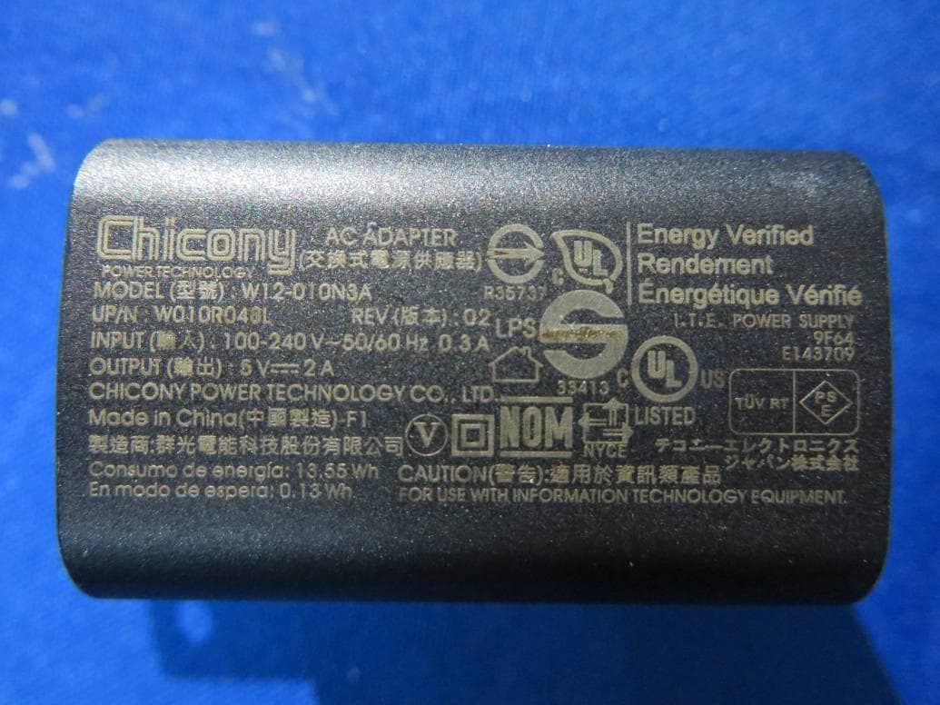
WL6-TE69SA3
Sep 22, 2015Tablet PC
Equipment Class
DSS - Part 15 Spread Spectrum Transmitter