WM45442.4 GHz Heart Rate Monitor
Latitude Limited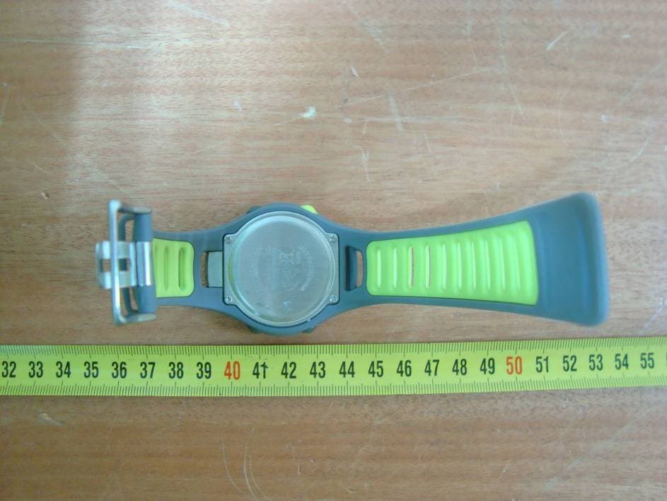
Click to zoom
Application Details
- Equipment Class
- DXX - Part 15 Low Power Communication Device Transmitter
- Date of Grant
- Sep 28, 2010
- Application Purpose
- Original Equipment
- Date of Application
- Sep 28, 2010
- Equipment Note
- 2.4 GHz Heart Rate Monitor
- Frequency Range
- 2440.00000000 - 2440.00000000
- Company
- Latitude Limited
- Country
- Hong Kong
Documents & Files
Document Text
Text extracted from the exhibit documents filed with the FCC. Open a document above to read the original.
Users Manual
Accelerator Pro & Accelerator Pro Plus Sports & Fitness Watches 10.0 Distance MoDe overview 10.1 Distance Mode - Capturing the Data 10.2 Distance Mode - Display 10.3 Distance Mode - Supplementary Function Menu 10.3.1 Distance Mode - Menu 1 Save a Session 10.3.2 Distance Mode - Menu 2 Session Review 10.3.3 Distance Mode - Menu 3 Daily Record Review 10.3.4 Distance Mode - Menu 4 Sleep Time Setting 10.3.5 Distance Mode - Menu 5 Sense Sensitivity Setting 11.0 Heart rate MoDe FUnctions 11.1 Heart Rate Mode - Chest Strap 11.2 Heart Rate Mode - Capture the Data 11.3 Heart Rate Mode - Function Display 11.4 Heart Rate Mode - EMHR and % EMHR 11.5 Heart Rate Mode - Zone Alert Limits 11.6 Heart Rate Mode - Turn ON/OFF Zone Alert 11.7 Heart Rate Mode - No Signal or Long Response Time 11.8 Heart Rate Mode - Supplementary Function Menu 11.8.1 Heart Rate Mode - Function Menu 1 Save Session 1.0 introDUction 1.1 What the Buttons Do 2.0 tiMekeeping & sensor MenUs 3.0 cUrrent tiMe MoDe - set tHe watcH 4.0 alarM MoDe - setting on/oFF 4.1 Alarm Mode - Setting Alarms 5.0 cHronograpH MoDe - How to Use 5.1 Chronograph Mode - Recall Lap Time 6.0 ti Mer MoDe - set a target tiMe 6.1 Timer Mode - Establish User Presets 6.2 Timer Mode - Use the Countdown Timer 7.0 pace tiMe MoDe - How to Use 7.1 Pace Mode - Set a Pace 7.2 Pace Mode - Use Pace with Chronograph 8.0 DUal tiMe MoDe 9.0 sensor MoDe - stop/start tHe sensor, tiMer & logbook 9.1 Sensor Mode - Reset Screen, Session & Timer 11.8.2 Heart Rate Mode - Function Menu 2 Session Review 11.8.3 Heart Rate Mode - Function Menu 3 Daily Record 11.8.4 Heart Rate Mode - Menu 4 Zone Setting 12.0 User MoDe FUnction MenU 12.1 User Mode - Capture the Data 12.2 User Mode - Change the Display 12.3 User Mode - Supplementary Function Menus 12.3.1 User Mode - Menu 1 Save Session 12.3.2 User Mode - Menu 2 Save Review 12.3.3 User Mode - Menu 3 Daily Record Review 12.3.4 User Mode - Menu 4 Display Setting 13.0 logbook MoDe FUnction MenU 13.0.1 Logbook Mode - Menu 1 View 13.0.2 Logbook Mode - Menu 2 Logbook Stop/Start 13.0.3 Logbook Mode - Menu 3 PC Link 13.0.4 Logbook Mode - Menu 4 Log Rate Setting 13.0.5 Logbook Mode - Menu 5 Log Auto Start 13.0.6 Logbook Mode - Menu 6 Erase Session for Logbook 13.0.7 Logbook Mode - Menu 7 View Free Memory 14.0 pc link installation 14.0.1 PC Link - Pair the Watch & Chest Strap with the Program 14.0.2 PC Link - Send Data to a PC through the PC Pod 14.0.3 PC Link - Download, Analyze & Save Data from the Watch 14.0.4 PC Link - Analyze & Save Real Time Data from the Chest Strap 15.0 replace tHe batteries 16.0 sleep MoDe li MiteD warranty Note: All of the above information in this color, refers to the Accelerator Pro Plus only. fig. 1 1.0 IntroductIon Thank you for purchasing this Tech4o Accelerator Pro Series Watch! We’ve done everything possible to insure that your watch is easy to use, with a logical screen flow using up/down buttons, and a one button escape. Stride length is important for accurate measures. Visit www.tech4o.com to use the stride length calculator on our customer support pages. 1.1 What the Buttons do As a convention, we use ▲ to indicate pressing the St/StP button and ▼ to indicate pressing the LAP/ rESEt button in all the illustrations. Also, these icons appear in the watch display whenever they are available. See fig 1. St/StP ▲ • Scrolls upward. • Increases values in Setting Mode. • Stops/Starts functions in Timer & Chrono modes. LAP/rESEt ▼ • Scrolls downward. • Decreases values in Setting Mode. • Activates the Reload function in Timer. • Resets the laps to zero in Chrono. ESc- • Selects between Time & Sensor mode. • Returns to previous screen or function. • Exits Sensor mode. • When held, turns on backlight. ModE - M • Selects among: Current Time, Daily Alarm, Chrono, Timer, Pacer & Dual Time modes. • Selects among: Distance, Heart Rate, User & Logbook modes. • Selects among items in Setting Display. ▲ ▼▼ ▼ ▼▼ ▼ see 2.1 Press to move in reverse direction fig. 2 Whenever you land on any of the Mode Menus, they will automatically enter their respective Function Menu after a few seconds or press M to go instantly to the function. Press ESc if you wish to back out of a Function Menu. 2.0 tIMEkEEPIng MEnuS: see fig 2. See 2.0 Press to move in the reverse direction fig. 3 SE nSor MEnuS: see fig. 3. Whenever you land on any of the Mode Menus, they will automatically enter their respective Function Menu after a few seconds. Press ESc if you wish to back out of a Function Menu. Exit the current display Return to the previous level Advance to the next level Scroll the menu Change the setting Scroll the menu Change the setting Confirm the selection or setting fig. 4 3.0 currEnt tIME ModE - SEt thE WAtch see fig. 4 * 1. Press M to confirm these selections. * 2. When Normal, press ESc to turn on. When Night, press any button to turn on. * 3. The Heart Rate Chest Strap must be worn for this to work. * 4. If Chime is on , the watch will beep once every hour on the hour. fig. 5 4.0 ALArM ModE - SEttIng on/off see fig. 5 If an Alarm is on , the watch will beep at your predetermined time, either daily or weekly. The Alarm will beep for 30 seconds. Press any button to stop it. Alarm1 and Alarm2 can be set independently for either daily or weekly. Press to move in the reverse direction fig. 6 4.1 Alarm Mode - Setting Alarms see fig. 6 * 1. When selected, Daily will beep at the same time every day of the week. * 2. When selected, Week Day will beep once a week at the same time on the same day of the week. lap number 10 seconds total elapsed time lap time freezes for 10 seconds *1 *2 fig. 7 5.0 chronogrAPh ModE - hoW to uSE see fig. 7 * 1. The Chronograph can record up to 50 lap times. * 2. With the Chronograph stopped, press and hold ▼ for 2 seconds to reset it. When reset, all recorded lap times will be erased. Press to move in the reverse direction fig. 8 5.1 chronograph Mode - recall Lap time see fig. 8 See the previous section to erase recorded la…
Text truncated - open the document above for the full version.
External Photos
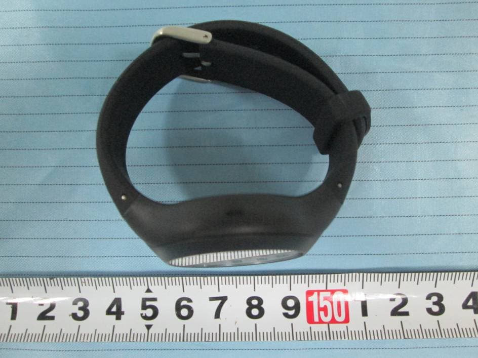
EXHIBIT B - EUT EXTERNAL PHOTOGRAPHS EUT – Top View EUT – Bottom View
ID Label/Location Info
EXHIBIT A - FCC ID LABELING AND LOCATION FCC ID Label FCC ID Label Location The label shown shall be permanently affixed at a conspicuous location on the device and be readily visible to the user at the time purchase (Labeling requirements per 2.925) Label here
Internal Photos
EXHIBIT C - EUT INTERNAL PHOTOGRAPHS EUT – Cover off View EUT – Main Part Top View Antenna EUT – Main Part Bottom View EUT – Main Part Cover off View EUT – Main Board Top View EUT – Main Board Bottom View Antenna Connector EUT – Battery View
Test Report
Note: This test report is prepared for the customer shown above and for the device described herein. It may not be duplicated or used in part without prior written consent from Bay Area Compliance Laboratories Corp. (Shenzhen). This report must not be used by the customer to claim product certification, approval, or endorsement by NVLAP*, NIST, or any agency of the Federal Government. * This report may contain data that are not covered by the NVLAP accreditation and are marked with an asterisk “*” (Rev.2) FCC PART 15.249 MEASUREMENT AND TEST REPORT For Latitude Limited 7/F, Southeast Industrial Building, 611-619 Castle Peak Road, N.T., Hong Kong FCC ID: WM4544 Report Type: Original Report Product Type: 2.4GHz Heart Rate Monitor Test Engineer: Jessica He Report Number: RSZ10080101 Report Date: 2010-09-02 Reviewed By: Merry Zhao EMC Engineer Prepared By: Bay Area Compliance Laboratories Corp. (Shenzhen) 6/F, the 3rd Phase of WanLi Industrial Building, ShiHua Road, FuTian Free Trade Zone Shenzhen, Guangdong, China Tel: +86-755-33320018 Fax: +86-755-33320008 Latitude Limited FCC ID: WM4544 Report No.:RSZ10080101 Page 2 of 17 FCC Part15.249 Test Report TABLE OF CONTENTS GENERAL INFORMATION.......................................................................................................................................3 PRODUCT DESCRIPTION FOR EQUIPMENT UNDER TEST (EUT) .....................................................................................3 OBJECTIVE...................................................................................................................................................................3 RELATED SUBMITTAL(S)/GRANT(S).............................................................................................................................3 TEST METHODOLOGY..................................................................................................................................................3 TEST FACILITY.............................................................................................................................................................3 SYSTEM TEST CONFIGURATION ..........................................................................................................................5 JUSTIFICATION.............................................................................................................................................................5 EQUIPMENT MODIFICATIONS.......................................................................................................................................5 BLOCK DIAGRAM OF TEST SETUP................................................................................................................................5 SUMMARY OF TEST RESULTS ...............................................................................................................................6 FCC §15.203 - ANTENNA REQUIREMENT.............................................................................................................7 APPLICABLE STANDARD..............................................................................................................................................7 ANTENNA CONNECTOR CONSTRUCTION......................................................................................................................7 FCC §15.205, §15.209 & §15.249 - RADIATED EMISSIONS ..................................................................................8 APPLICABLE STANDARD..............................................................................................................................................8 MEASUREMENT UNCERTAINTY....................................................................................................................................8 TEST EQUIPMENT SETUP..............................................................................................................................................8 EUT SETUP..................................................................................................................................................................9 TEST EQUIPMENT LIST AND DETAILS...........................................................................................................................9 TEST PROCEDURE......................................................................................................................................................10 CORRECTED AMPLITUDE & MARGIN CALCULATION.................................................................................................10 TEST RESULTS SUMMARY..........................................................................................................................................10 TEST DATA................................................................................................................................................................11 FCC §15.249(D) – OUT OF BAND EMISSIONS .....................................................................................................14 APPLICABLE STANDARD............................................................................................................................................14 TEST PROCEDURE......................................................................................................................................................14 MEASUREMENT UNCERTAINTY..................................................................................................................................14 TEST EQUIPMENT SETUP............................................................................................................................................14 TEST EQUIPMENT LIST AND DETAILS.........................................................................................................................14 TEST DATA...............................................................…
Text truncated - open the document above for the full version.
Test Setup Photos
EXHIBIT D - TEST SETUP PHOTOGRAPHS Radiated Emissions - Front View (Below 1 GHz) Radiated Emissions - Rear View (Below 1 GHz) Radiated Emissions - Front View (Above 1 GHz) Radiated Emissions - Rear View (Above 1 GHz)
Contact Information
Applicant
Kam Kwok(Senior Electronic Engineer)
Test Firm
Bay Area Compliance Laboratory Corp. (Shenzhen)John Chan
Technical Specifications
| # | Rule Parts | Frequency Range | Power Output |
|---|---|---|---|
| 1 | 15C | 2.44 GHz - 2.44 GHz | - |
Other Applications from Latitude Limited
WM4804
Sep 10, 2015BLE Analog Watch
Equipment Class
DTS - Digital Transmission System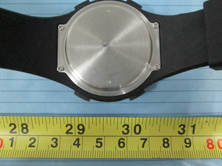
WM4796
May 04, 2015BLE Analog Watch
Equipment Class
DTS - Digital Transmission System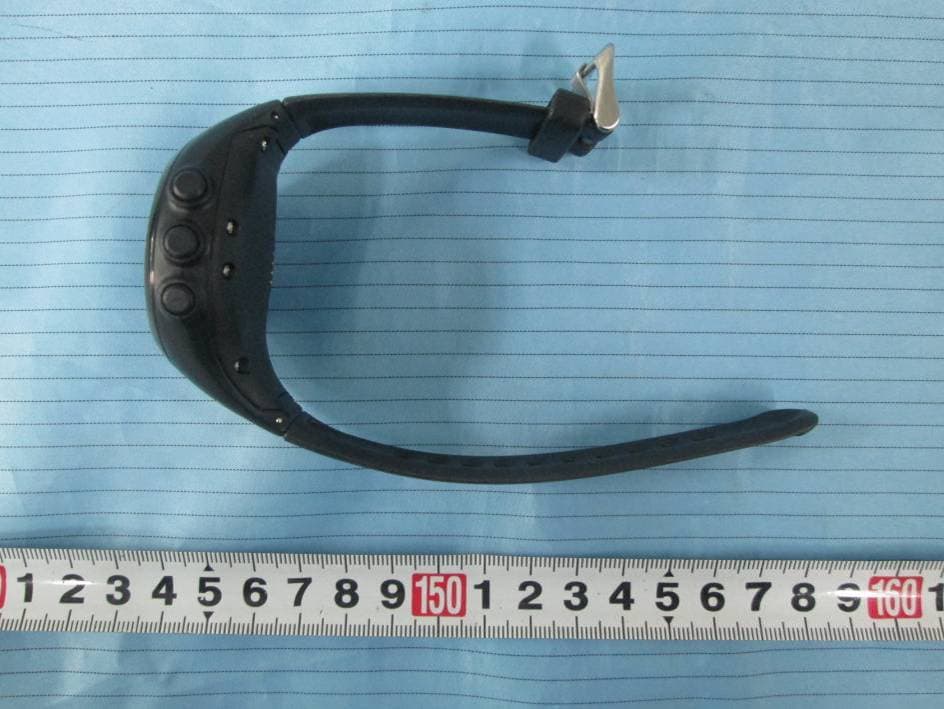
WM4745
Mar 18, 2015Bluetooth GPS Watch
Equipment Class
DTS - Digital Transmission System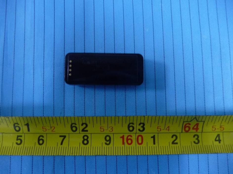
WM4760
Jun 01, 2014LED Wrist Band
Equipment Class
DTS - Digital Transmission System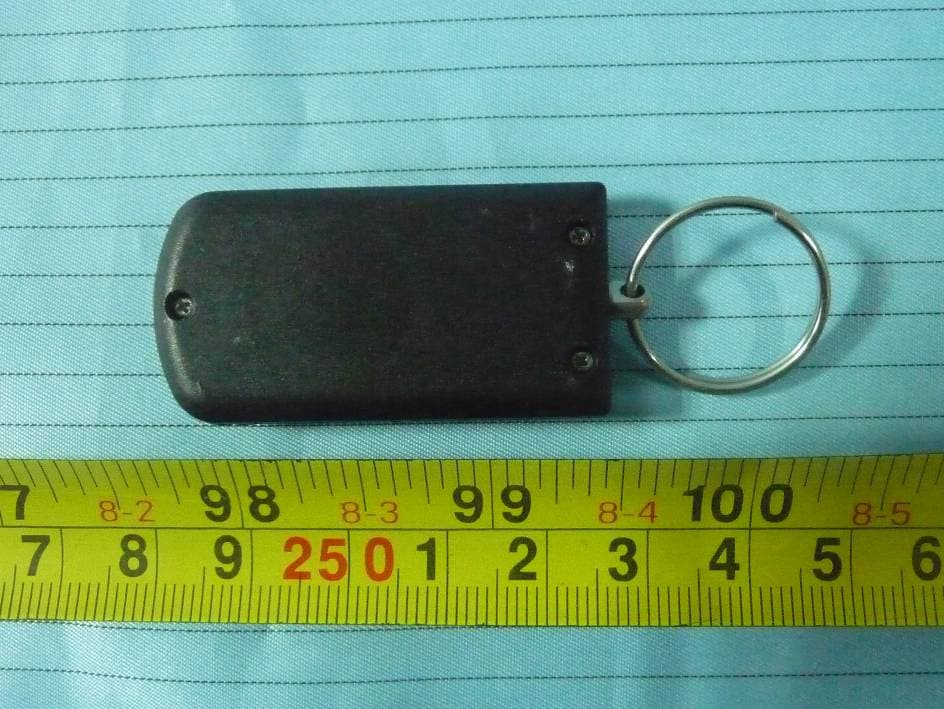
WM4719
Jan 21, 2014Keyfob
Equipment Class
DTS - Digital Transmission System