WMSBETX1Optical Smoke Alarm
Bellman & Symfon Europe AB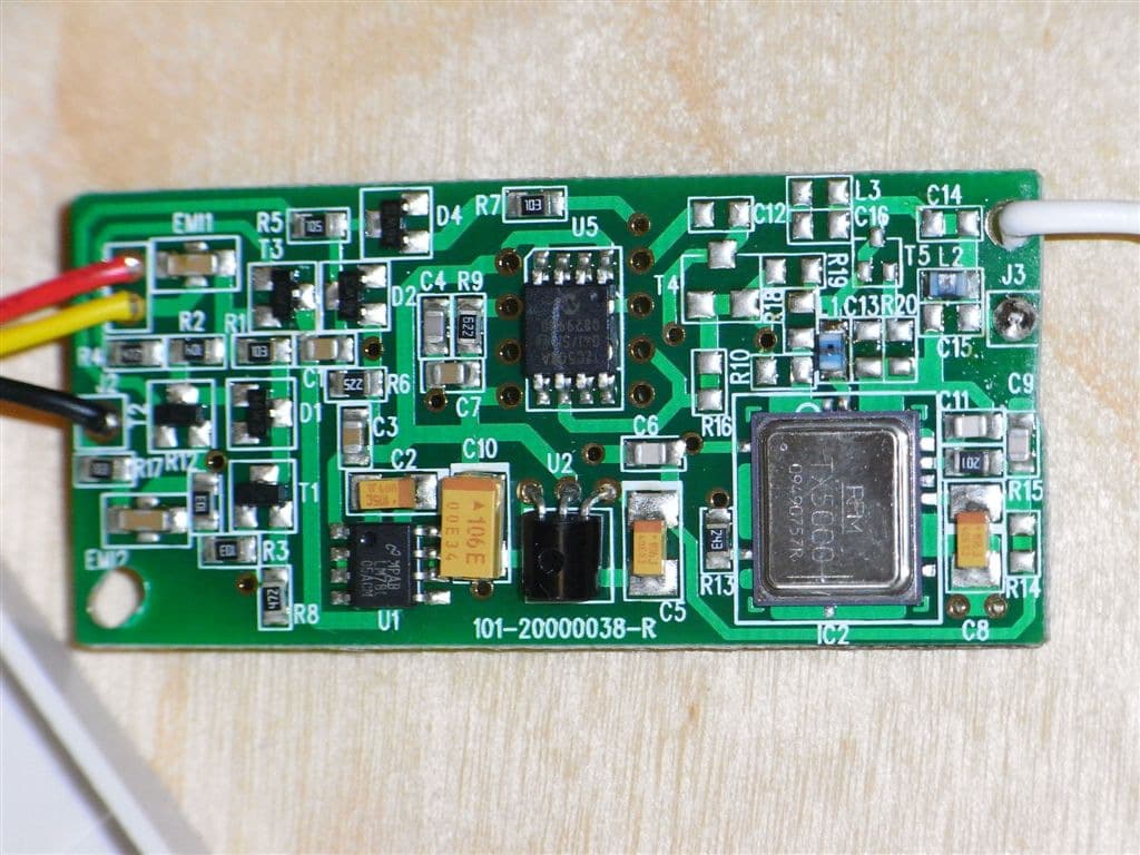
Click to zoom
Application Details
- Equipment Class
- DSC - Part 15 Security/Remote Control Transmitter
- Date of Grant
- May 11, 2010
- Application Purpose
- Original Equipment
- Date of Application
- May 11, 2010
- Equipment Note
- Optical Smoke Alarm
- Frequency Range
- 433.92000000 - 433.92000000
- Company
- Bellman & Symfon Europe AB
- Country
- Sweden
Documents & Files
Document Text
Text extracted from the exhibit documents filed with the FCC. Open a document above to read the original.
Users Manual
Bellman Visit Smoke Alarm Transmitter Board Model BE1282 Attention: The enclosed product contains small parts which may constitute choking hazard to children. Operation is subject to the following two conditions: (1) This device may not cause harmful interference, and (2) This device must accept any interference received, including interference that may cause undesired operation. This product meets the applicable Industry Canada technical specifications. Made in P.R.C Warning: Changes or modifications to this unit not expressly approved by the party responsible for compliance could void the user’s authority to operate the equipment. Bellman Visit 433,92 MHz FCC approvals FCC ID:WMSBETX1 IC:6693A-BETX1 5 76 1) Antenne 2) Bouton de test 3) Compartiment à pile 4) Plaque de fixation 5) Languette de verrouillage 6) Emetteur Alarme incendie Bellman Visit 7) Détecteur de fumée Garvan Mode d’emploi de l’Emetteur Alarme incendie Bellman Visit L’Emetteur Alarme incendie Bellman Visit fait partie du système Visit. L’Emetteur Alarme incendie, déclenché par la présence de fumée ou d’un incendie transmet un signal aux récepteurs Bellman Visit. Procédez de la manière suivante ! 1. Lisez attentivement les modes d’emploi et les manuels d’entretien de Garvan et de Bellman & Symfon. 2. Suivez les instructions de Garvan pour installer l’émetteur et pour mettre la pile. Une fois l’Emetteur Alarme incendie installé, tirez l’antenne (1) et dirigez-la vers le sol. 3. Activez l’émetteur en appuyant sur le bouton de test (2). Vérifiez que le récepteur Bellman Visit reçoit les signaux provenant de l’Emetteur d’Alarme incendie. Pour ce test, il est souhaitable de demander l’aide d’une personne de votre entourage. Vérifiez surtout que la réception est bonne dans les chambres à coucher. Description du produit : En cas de panne Une panne n’est pas toujours grave. Lisez attentivement la liste de contrôles ci-dessous avant de contacter votre revendeur. DescriptionIntervention Le récepteur Bellman Visit se déclenche sans raison. Changez la pile de l’émetteur. Le récepteur ne réagit pas lorsqu’il reçoit un signal en provenance de l’Emetteur Alarme incendie. 1) Vérifiez que l’antenne est bien dirigée vers le sol. 2) Contrôlez les piles du récepteur. Veuillez consulter le manuel d’utilisateur de Garvan pour plus d’informations. Bouton test avec témoin lumineux L’Emetteur Alarme incendie a un bouton test avec un témoin lumineux rouge. Ce temoin clignote une ou deux fois par minute, indiquant que la pile est bien positionnée et chargée. Pour tester l’Emetteur Alarme incendie, appuyez sur le bouton de test pendant quelques secondes. Les récepteurs Bellman Visit réagissent par l’émission de signaux sonores et lumineux ou vibratoires, selon le type de récepteur. Localisation FR GB HU IT NL NO PL PT SE YU Installation Détachez la plaque de fixation: pressez la languette de verrouillage à l’aide d’un tournevis et poussez l’Émetteur Alarme incendie dans le sens opposé. Insérez la pile. Appuyez sur le bouton de test pendant quelques secondes jusqu’à ce que le récepteur Bellman Visit réagisse. Dans ce cas, l’unité fonctionne correctement et peut être installée. Fixez d’abord la plaque de fixation au plafond à l’aide des vis fournies. Ensuite, l’Emetteur Alarme incendie doit être inséré et glissé en place jusqu’à ce qu’il clique contre la languette de verrouillage. InstallerDétacher Test et entretien Vérifiez le fonctionnement de l’émetteur d’alarme au moins une fois par mois, de préférence une fois par semaine. Testez toujours après une absence prolongée, par exemple après des vacances. L’émetteur peut être testé en appuyant sur le bouton test pendant cinq secondes ou en souf- flant de la fumée vers l’émetteur d’alarme. Celui-ci émet alors un son et transmet un signal vers le récepteur Bellman Visit tant qu’il détecte de la fumée dans l’émetteur. Si l’unité ne fonctionne pas, vérifiez que la pile est insérée correctement ou changez-la. Le temoin lumineux rouge incorporé au bouton de test clignote une ou deux fois par minute et indique que la pile est insérée correctement et fournit suffisament d’énergie pour activer l’alarme. Pour l’entretien du détecteur de fumée, veuillez consulter le manuel d’utilisateur de Garvan. Piles La portée entre l’émetteur et le récepteur est de 30 m, mais peut être influencée par l’épaisseur des murs ainsi que par leur composition. Les murs en béton armé limitent la portée. La portée est aussi limitée quand la pile est faible. Contrôlez que votre récepteur reçoit le signal partout dans votre appartement/maison, particulièrement dans votre chambre à coucher. Portée L’Alarme incendie Bellman Visit émet sur une fréquence fixe. Les récepteurs réagissent à tous les Emetteurs Alarme incendie et la fréquence du récepteur n’est pas importante. Fréquence Radio La durée de vie de la pile est d’environ un an. N’utilisez que des piles neuves de 9 V, de préférence de type alcalines. Vérifiez le fonctionne- ment de L’Emetteur Alarme incendie après avoir remplacé la pile. IMPORTANT! Pour les alarmes venant de l'Emetteur Alarme incendie, les signaux des récepteurs peuvent être arrêtés uniquement en adressant la cause de l'alarme, par exemple fumée ou incendie. Si le niveau de la batterie est bas, l'Emetteur Alarme incendie active de courts signaux sonores. Les alarmes du système Visit sont seulement un complément au fonctionnement autonome de l'Emetteur Alarme incendie. Le bon fonctionnement du système Visit est dépendant d'un environnement et d'une portée adéquats. S’il y a le feu dans votre maison, la survie de votre famille se joue en quelques secondes. Tout le monde dans la maison doit être préparé à ce type de situation. Préparez-vous à un incendie FR GB HU IT NL NO PL PT SE YU Comment éviter un incendie Ne laissez pas d’allumettes à la portée des enfants. Veillez à éteindre les bougies quand vous quittez la maison. Ne videz jamais de cendriers dans une corbeille à papier. Mettez de l’eau dans le cendrier avant de l…
Text truncated - open the document above for the full version.
Users Manual
BE1282_004MAN005 Bellman & Symfon AB Södra Långebergsgatan 30 SE-421 32 Västra Frölunda Sweden Tel. +46 31 68 28 20 Fax. +46 31 68 28 90 [email protected] www.bellman.com Bellman Visit Smoke Alarm Transmitter Board Model BE1282 FR GB Mode d’emploi Instructions Pro bezpečnost vašich dětí Tento výrobek může obsahovat malé části. Udržujte obal a malé části mimo dosah dětí. Zum Schutz Ihrer Kinder. Bitte beachten Sie, dass dieses Produkt Kleinteile enthalten kann. Stellen Sie sicher, dass Verpackung und Kleinteile nicht in Reichweite von Kindern geraten. Af hensyn til dine børns sikkerhed Vær opmærksom på, at dette produkt kan indeholde små dele. Sørg for, at både pakning og små dele opbevares utilgængeligt for børn. Para la seguridad de sus hijos Tenga en cuenta que este producto puede incluir piezas pequeñas. Asegúrese de mantener el embalaje y las piezas pequeñas fuera del alcance de los niños. Lastesi turvallisuuden vuoksi Huomaa, että tämä tuote voi sisältää pieniä osia. Varmista, että pakkaus ja pienet osat pidetään poissa lapsesi ulottuvilta. Pour la sécurité de vos enfants Veuillez ne pas oublier que ce produit peut comprendre des petites pièces. Assurez-vous que le paquet et les petites pièces sont gardés hors de portée de votre enfant. For the safety of your children Please be aware that this product may include small parts. Ensure that the package and small parts are kept out of reach from your child. A gyermekek biztonsága érdekében A termék kisméretű alkatrészeket tartalmazhat. A csomagolást és a kis alkatrészeket gyermekek elől elzárva tartsa. Per la sicurezza dei bambini: si ricorda che il prodotto può contenere parti di piccole dimensioni. Tenere la confezione e le parti di piccole dimensioni lontano dalla portata dei bambini. Voor de veiligheid van uw kinderen. Hou er rekening mee dat dit product kleine onderdelen kan bevatten. Zorg ervoor dat de verpakking en de kleine onderdelen buiten het bereik van uw kind worden gehouden. For dine barns sikkerhet Vær oppmerksom på at dette produktet kan inneholde små deler. Påse at innpakningen og små deler holdes utenfor ditt barns rekkevidde. Bezpieczeństwo dzieci Pamiętaj, że ten produkt może zawierać małe elementy. Przechowuj opakowanie i małe elementy poza zasięgiem dziecka. Para a segurança das crianças Tenha em atenção que este produto pode conter peças de pequenas dimensões. Mantenha a embalagem e as peças pequenas fora do alcançe das crianças. För barnens säkerhet Observera att den här produkten kan innehålla smådelar. Se till att förpackningen och smådelarna förvaras utom räckhåll för barn. Za sigurnost Vaše dece Budite svjesni da ovaj proizvod može sadržati male deliće. Pazite da paket i mali delovi budu izvan dohvata dece.
External Photos
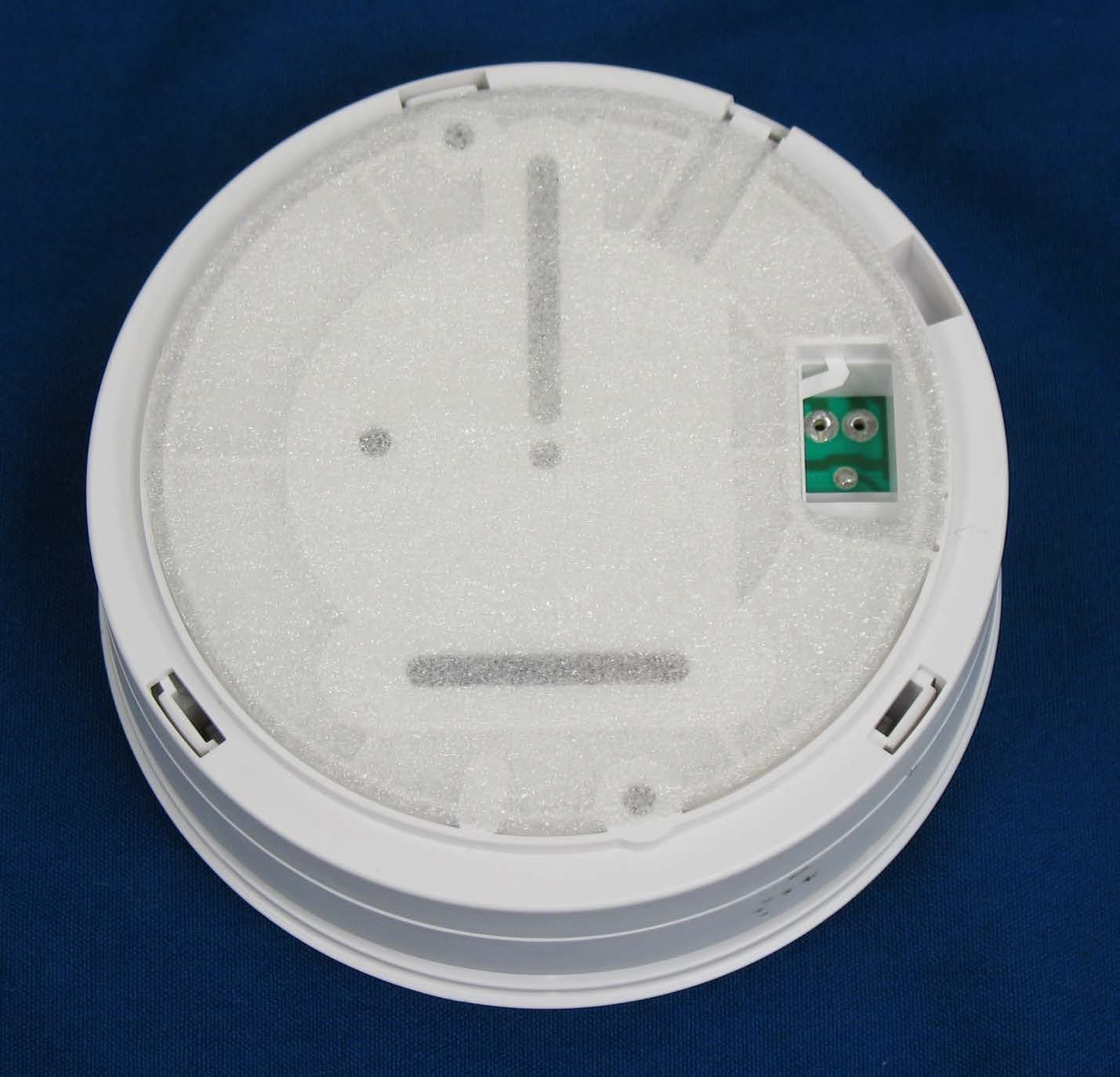
External and internal photos of BE1282 Smoke Alarm B&S Transmitter PCB including Power latch, Voltage regulator, CPU. B&S Transmitter PCB, rear side Main Smoke Detector PCB and Connector board for Transmitter. Main Smoke Detector PCB and Connector board for Transmitter, Rear side.
Internal Photos
External and internal photos of BE1282 Smoke Alarm B&S Transmitter PCB including Power latch, Voltage regulator, CPU. B&S Transmitter PCB, rear side Main Smoke Detector PCB and Connector board for Transmitter. Main Smoke Detector PCB and Connector board for Transmitter, Rear side.
Operational Description
Bellman & Symfon AB Page 1 (3) Document title Document no. Revision Visit 433 Radio description and calculation for Canada Visit433_001DSP 002 Issued by Date Approved by: Date: Info class: Stefan Lundgren 2006-06-28 - Strictly confidential File name: g:\alla\avd800\re810_utveckling\05_bv433\visit433_north america\visit433_001dsp002_visit433 description and caluclation for canada.doc REVISION DATE PARAGRAPHS CHANGED SIGN. 001A 2006-06-16 Initial version Slu 002 2006-06-28 Calculation changed to worst case Slu TABLE OF CONTENTS: 1 Visit 433 Radio interface............................................................................................................................ 2 1.1 GENERAL................................................................................................................................. 2 1.2 FREQUENCY BAND................................................................................................................... 2 1.3 MODULATION.......................................................................................................................... 2 1.4 F RAME FORMAT....................................................................................................................... 2 1.5 OUTPUT POWER CALCULATION................................................................................................ 3 Bellman & Symfon AB Page 2 (3) Document title Document no. Revision Visit 433 Radio description and calculation for Canada Visit433_001DSP 002 Issued by Date Approved by: Date: Info class: Stefan Lundgren 2006-06-28 - Strictly confidential File name: g:\alla\avd800\re810_utveckling\05_bv433\visit433_north america\visit433_001dsp002_visit433 description and caluclation for canada.doc 1 Visit 433 Radio interface 1.1 General The wireless communication shall use the 433 MHz SRD radio spectrum according to CEPT ERC recommendation 70-03E. 1.2 Frequency band Carrier frequency shall be 433.92 MHz (± 200 kHz). 1.3 Modulation Baud rate is approximately 333.34 bit/s. On-Off Keying shall be used for modulation, where carrier present = “1”, no carrier = “0”. 1.4 Frame format Data is transferred in a frame-format beginning with a back-off time of 12 bits, a reference bit (1/3 bit length) and 12 information bits. The information bits represents 8 address-bits and 4 data bits, where the address corresponds to the selected channel and the 4 data bits holds information about that kind of alarm event that has occurred. Bellman & Symfon AB Page 3 (3) Document title Document no. Revision Visit 433 Radio description and calculation for Canada Visit433_001DSP 002 Issued by Date Approved by: Date: Info class: Stefan Lundgren 2006-06-28 - Strictly confidential File name: g:\alla\avd800\re810_utveckling\05_bv433\visit433_north america\visit433_001dsp002_visit433 description and caluclation for canada.doc back-off time Info.bits Info.bits Info.bits reference bit back-off time frame 1 frame 2 frame n A0 A1 A2 A3 A4 A5 A6 A7 D0 D1 D2 D3 reference bit ”1” ”1” ”1” ”0” ”0” Figure 1: Visit frame format The information bits are encoded using two different pulse-widths for representation of “1” and “0”. The reference bit must be used as a timing reference, in order to decide the logical level of the received bits. The length of the reference bit is measured and a constant is added to achieve a threshold time. A measured pulse of the information bits that is longer than the threshold is considered a logical “0” and a shorter pulse is considered logical “1”. An alarm event will repeat transmit frames for a minimum of 1.3 s. The back-off time between frames should be at least the pilot time, which is 36 ms (12 bits). The receiver expects no transmission for approximately 4-6ms (depending on product) before the reference bit is measured. At least 3 identical frames must be received before an alarm event is triggered in the receiver. 1.5 Output power calculation According to RSS-210e table 4 the upper allowed limit to transmit is 10972uV/m measured with an average method meter. Since Visit433 System is using On-Off keying modulation technique it is not possible to use the average method directly. Therefore, according to NEMKO, the radio power level is measured with peak measurement method and then calculated with the formula: 20*log(on time in 100ms/100ms). The Visit433 system message is designed with a back-off time, radio message, back-off time, radio message for about 1.3 seconds. The bit time is 3ms. 1. Message 1: a. Reference bit: 1/3 bit time 1/3*3= 1ms Bellman & Symfon AB Page 4 (3) Document title Document no. Revision Visit 433 Radio description and calculation for Canada Visit433_001DSP 002 Issued by Date Approved by: Date: Info class: Stefan Lundgren 2006-06-28 - Strictly confidential File name: g:\alla\avd800\re810_utveckling\05_bv433\visit433_north america\visit433_001dsp002_visit433 description and caluclation for canada.doc b. 12 bits with max on time of 2/3 bit time 2/3*12*3= 24ms Total on 1: 25ms 2. Message 2: Length 100ms-37ms(message 1)-36ms(back-off time)=27ms 25ms*27/37 18.24ms Total on 2: 18.24ms Total on time/100ms 43.24ms Peak value: 20*log(43.24ms/100ms)= -7.28db higher than 10972uV/m which gives 25367uV/m at 3m.
Test Report
www.nemko.com Nemko Canada Inc., 303 River Road, R.R. 5, Ottawa, Ontario, Canada, K1V 1H2 Report number: 148080-1TRFWL Apparatus: Smoke Alarm Transmitter (BE1282) Applicant: Bellman & Symfon AB Sodra Langebergsgatan 30 Vastra Frolunda 421 32, Sweden FCC ID: WMSBETX1 IC Registration Number: 6693A-BETX1 Test specifications: − FCC §15.231 – Periodic operation in the band 40.66–40.70 MHz and above 70 MHz − RSS-210, Issue 7, Annex 1.1 – Momentarily operated devices Emissions verification Reviewed by: May 6, 2010 Signature Date Kevin Ma, Wireless/EMC Specialist Tested by: Andrey Adelberg, Senior Wireless/EMC Specialist Nemko Canada Inc. authorizes the applicant to reproduce this report provided it is reproduced in its entirety and for use by the company’s employees only. Any use which a third party makes of this report, or any reliance on or decisions to be made based on it, are the responsibility of such third parties. Nemko Canada Inc. accepts no responsibility for damages, if any suffered by any third party as a result of decisions made or actions based on this report. This report shall not be reproduced except in full without the written approval of the testing laboratory. Nemko Canada Inc., a testing laboratory, is accredited by the Standards Council of Canada. The tests included in this report are within the scope of this accreditation. Report Number: 148080-1TRFWL Nemko Canada Inc., 303 River Road, R.R. 5, Ottawa, Ontario, Canada, K1V 1H2 Specification: FCC 15.231/RSS-210 A1.1 Page 2 of 20 Table of contents Section 1: Report summary.....................................................................................................................3 Section 2: Equipment under test.............................................................................................................4 2.1 Identification of equipment under test (EUT)...............................................................................4 2.2 EUT description...........................................................................................................................4 2.3 Technical specifications of the EUT............................................................................................4 2.4 EUT setup diagram.....................................................................................................................5 2.5 Operation of the EUT during testing............................................................................................5 2.6 Modifications incorporated in the EUT........................................................................................5 Section 3: Test conditions.......................................................................................................................6 3.1 Deviations from laboratory tests procedures...............................................................................6 3.2 Test conditions, power source and ambient temperatures..........................................................6 3.3 Measurement uncertainty............................................................................................................7 3.4 Test equipment............................................................................................................................7 Section 4: Result summary......................................................................................................................8 4.1 FCC Part 15 Subpart C, 15.231: Test results..............................................................................8 4.2 RSS-210 Annex A1.1: Test results..............................................................................................8 Appendix A: Test results..........................................................................................................................9 Clause 15.31(e) Variation of the power source.....................................................................................9 Clause 15.203 Antenna requirement...................................................................................................10 Clause 15.231(a) Conditions for intentional radiators to comply with periodic operation....................11 FCC 15.231(b): Field strength of emissions and RSS-210 A1.1.2: Field strengths and frequency bands ..................................................................................................................................................13 Clause 15.231(c) Emission bandwidth................................................................................................18 Appendix B: Block diagrams of test set-ups........................................................................................20 Section 1: Report summary Report Number: 148080-1TRFWL Nemko Canada Inc., 303 River Road, R.R. 5, Ottawa, Ontario, Canada, K1V 1H2 Specification: FCC 15.231/RSS-210 A1.1 Page 3 of 20 Section 1: Report summary This report contains an assessment of apparatus against specifications based upon tests carried out on samples submitted at Nemko Canada Inc. Test specifications: FCC Part 15 Subpart C, 15.231 Periodic operation in the band 40.66–40.70 MHz and above 70 MHz. RSS-210, Issue 7, Annex 1.1 Momentary Operated Devices Compliance status: Complies Exclusions: Only partial tests for IC were performed. Non-compliances: None Report release history: Original release Test location: Nemko Canada Inc. 303 River Road, R.R. 5, Ottawa, Ontario, Canada, K1V 1H2 FCC Registration number: 176392 (3 m Semi anechoic chamber) IC Registration number: 2040A-4 (3 m Semi anechoic chamber) Note that the results contained in this report relate only to the items tested and were obtained in the period between the date of initial receipt of samples and the date of issue of the report. This test report has been completed in accordance with the requirements of ISO/IEC 17025. All results contain in this report are within Nemko Canada’s ISO/IEC 17025 accreditation…
Text truncated - open the document above for the full version.
Contact Information
Applicant
Aki Tapani Nummela(CTO)
Technical Contact
Bellman &Symfon Europe ABPeter Jungvid
[email protected]46 31 68 28 20
Sodra Langebergsgatan 30 · Vastra Frolunda · Sweden
Non-Technical Contact
Bellman &Symfon Europe ABPeter Jungvid
[email protected]46 31 68 28 20
Test Firm
Nemko Canada Inc. (Ottawa)Charles Neal
Technical Specifications
| # | Rule Parts | Frequency Range | Power Output |
|---|---|---|---|
| 1 | 15.231 | 433.92 MHz - 433.92 MHz | - |
Other Applications from Bellman & Symfon Europe AB
WMSBETXSA2
Aug 18, 2015BE1281 Optical Smoke Alarm Transmitter
Equipment Class
DSC - Part 15 Security/Remote Control Transmitter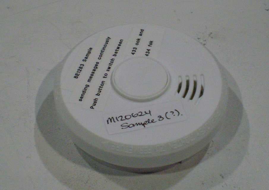
WMSBETXSA
Dec 10, 2012BE1283 OPTICAL SMOKE ALARM
Equipment Class
DSC - Part 15 Security/Remote Control Transmitter
WMSBETX2
Feb 08, 2011Pushbuton Transmitter
Equipment Class
DSC - Part 15 Security/Remote Control Transmitter