WMSBETX2Pushbuton Transmitter
Bellman & Symfon Europe AB
Click to zoom
Application Details
- Equipment Class
- DSC - Part 15 Security/Remote Control Transmitter
- Date of Grant
- Feb 08, 2011
- Application Purpose
- Original Equipment
- Date of Application
- Feb 02, 2011
- Equipment Note
- Pushbuton Transmitter
- Frequency Range
- 433.92000000 - 433.92000000
- Company
- Bellman & Symfon Europe AB
- Country
- Sweden
Documents & Files
Document Text
Text extracted from the exhibit documents filed with the FCC. Open a document above to read the original.
Operational Description
Bellman & Symfon AB Page 1 (3) Document title Document no. Revision BE1240 Radio and Antenna description BE1240_018DSP 001 Issued by Date Approved by: Date: Info class: Göran Ivarsson 2011-02-03 - Strictly confidential File name: g:\alla\avd800\re810_utveckling\05_bv433\be1240_push button transmitter bv 433\approvals\nemko\assessment summary\be1240_018dsp001 radio and antenna description.doc REVISION DATE PARAGRAPHS CHANGED SIGN. 001 2011-02-03 Description for BE1240 Giv TABLE OF CONTENTS: 1 Visit 433 Radio interface............................................................................................................................ 2 1.1 GENERAL................................................................................................................................. 2 1.2 FREQUENCY BAND................................................................................................................... 2 1.3 MODULATION.......................................................................................................................... 2 1.4 FRAME FORMAT....................................................................................................................... 2 1.5 ANTENNA................................................................................................................................. 3 Bellman & Symfon AB Page 2 (3) Document title Document no. Revision BE1240 Radio and Antenna description BE1240_018DSP 001 Issued by Date Approved by: Date: Info class: Göran Ivarsson 2011-02-03 - Strictly confidential File name: g:\alla\avd800\re810_utveckling\05_bv433\be1240_push button transmitter bv 433\approvals\nemko\assessment summary\be1240_018dsp001 radio and antenna description.doc 1 Visit 433 Radio interface 1.1 General The wireless communication shall use the 433 MHz SRD radio spectrum according to CEPT ERC recommendation 70-03E. 1.2 Frequency band Carrier frequency shall be 433.92 MHz (± 200 kHz). 1.3 Modulation Baud rate is approximately 333.34 bit/s. On-Off Keying shall be used for modulation, where carrier present = “1”, no carrier = “0”. 1.4 Frame format Data is transferred in a frame-format beginning with a back-off time of 12 bits, a reference bit (1/3 bit length) and 12 information bits. The information bits represents 8 address-bits and 4 data bits, where the address corresponds to the selected channel and the 4 data bits holds information about that kind of alarm event that has occurred. Bellman & Symfon AB Page 3 (3) Document title Document no. Revision BE1240 Radio and Antenna description BE1240_018DSP 001 Issued by Date Approved by: Date: Info class: Göran Ivarsson 2011-02-03 - Strictly confidential File name: g:\alla\avd800\re810_utveckling\05_bv433\be1240_push button transmitter bv 433\approvals\nemko\assessment summary\be1240_018dsp001 radio and antenna description.doc back-off time Info.bits Info.bits Info.bits reference bit back-off time frame 1 frame 2 frame n A0 A1 A2 A3 A4 A5 A6 A7 D0 D1 D2 D3 reference bit ”1” ”1” ”1” ”0” ”0” Figure 1: Visit frame format The information bits are encoded using two different pulse-widths for representation of “1” and “0”. The reference bit must be used as a timing reference, in order to decide the logical level of the received bits. The length of the reference bit is measured and a constant is added to achieve a threshold time. A measured pulse of the information bits that is longer than the threshold is considered a logical “0” and a shorter pulse is considered logical “1”. An alarm event will repeat transmit frames for a minimum of 1.3 s. The back-off time between frames should be at least the pilot time, which is 36 ms (12 bits). The receiver expects no transmission for approximately 4-6ms (depending on product) before the reference bit is measured. At least 3 identical frames must be received before an alarm event is triggered in the receiver. 1.5 Antenna Antenna type; Integral Helical Coil, Maximum antenna gain: -15.85 dBi.
Test Report
www.nemko.com Nemko Canada Inc., 303 River Road, R.R. 5, Ottawa, Ontario, Canada, K1V 1H2 Report number: 160429-1TRFWL Apparatus: Push Button Transmitter Applicant: Bellman & Symfon AB Sodra Langebergsgatan 30 Vastra Frolunda 421 32, Sweden FCC ID: WMSBETX2 Test specification: Title 47-Telecommunication Chapter I - Federal Communications Commission Subchapter A - General Part 15 - Radio Frequency Devices Subpart C - Intentional Radiators §15.231- Periodic operation in the band 40.66–40.70 MHz and above 70 MHz Reviewed by: January 5, 2011 Signature Date Richard Brazeau, Laboratory Manager Tested by: Kevin Ma, Technical Assessor Nemko Canada Inc. authorizes the applicant to reproduce this report provided it is reproduced in its entirety and for use by the company’s employees only. Any use which a third party makes of this report, or any reliance on or decisions to be made based on it, are the responsibility of such third parties. Nemko Canada Inc. accepts no responsibility for damages, if any suffered by any third party as a result of decisions made or actions based on this report. This report shall not be reproduced except in full without the written approval of the testing laboratory. Nemko Canada Inc., a testing laboratory, is accredited by the Standards Council of Canada. The tests included in this report are within the scope of this accreditation. Report Number: 160429-1TRFWL Nemko Canada Inc., 303 River Road, R.R. 5, Ottawa, Ontario, Canada, K1V 1H2 Specification: FCC 15.231 Page 2 of 19 Table of contents Section 1: Report summary.....................................................................................................................3 Section 2: Equipment under test.............................................................................................................4 2.1 Identification of equipment under test (EUT)...............................................................................4 2.2 Accessories and support equipment...........................................................................................4 2.3 EUT description...........................................................................................................................4 2.4 Technical specifications of the EUT............................................................................................4 2.5 EUT setup diagram.....................................................................................................................5 2.6 Operation of the EUT during testing............................................................................................5 2.7 Modifications incorporated in the EUT........................................................................................5 Section 3: Test conditions.......................................................................................................................6 3.1 Deviations from laboratory tests procedures...............................................................................6 3.2 Test conditions, power source and ambient temperatures..........................................................6 3.3 Measurement uncertainty............................................................................................................7 3.4 Test equipment............................................................................................................................7 Section 4: Result summary......................................................................................................................8 4.1 FCC Part 15 Subpart C, 15.231: Test results..............................................................................8 Appendix A: Test results..........................................................................................................................9 Clause 15.31(e) Variation of the power source..................................................................................9 Clause 15.203 Antenna requirement...................................................................................................10 Clause 15.231(a) Conditions for intentional radiators to comply with periodic operation....................11 Clause 15.231(b) Field strength of emissions.....................................................................................13 Clause 15.231(c) Emission bandwidth................................................................................................18 Appendix B: Block diagrams of test set-ups........................................................................................19 Section 1: Report summary Report Number: 160429-1TRFWL Nemko Canada Inc., 303 River Road, R.R. 5, Ottawa, Ontario, Canada, K1V 1H2 Specification: FCC 15.231 Page 3 of 19 Section 1: Report summary This report contains an assessment of apparatus against specifications based upon tests carried out on samples submitted at Nemko Canada Inc. Test specification: FCC Part 15 Subpart C, 15.231 Periodic operation in the band 40.66–40.70 MHz and above 70 MHz. Compliance status: Complies Exclusions: None Non-compliances: None Report release history: Original release Test location: Nemko Canada Inc. 303 River Road, R.R. 5, Ottawa, Ontario, Canada, K1V 1H2 Registration number: 176392 (3 m Semi anechoic chamber) Note that the results contained in this report relate only to the items tested and were obtained in the period between the date of initial receipt of samples and the date of issue of the report. This test report has been completed in accordance with the requirements of ISO/IEC 17025. All results contain in this report are within Nemko Canada’s ISO/IEC 17025 accreditation. Nemko Canada Inc. authorizes the applicant to reproduce this report provided it is reproduced in its entirety and for use by the company’s employees only. Any use which a third party makes of this report, or any reliance on or decisions to be made based on it, are the responsibility of suc…
Text truncated - open the document above for the full version.
Contact Information
Applicant
Aki Tapani Nummela(CTO)
Test Firm
Nemko Canada Inc. (Ottawa)Charles Neal
Technical Specifications
| # | Rule Parts | Frequency Range | Power Output |
|---|---|---|---|
| 1 | 15.231 | 433.92 MHz - 433.92 MHz | - |
Other Applications from Bellman & Symfon Europe AB
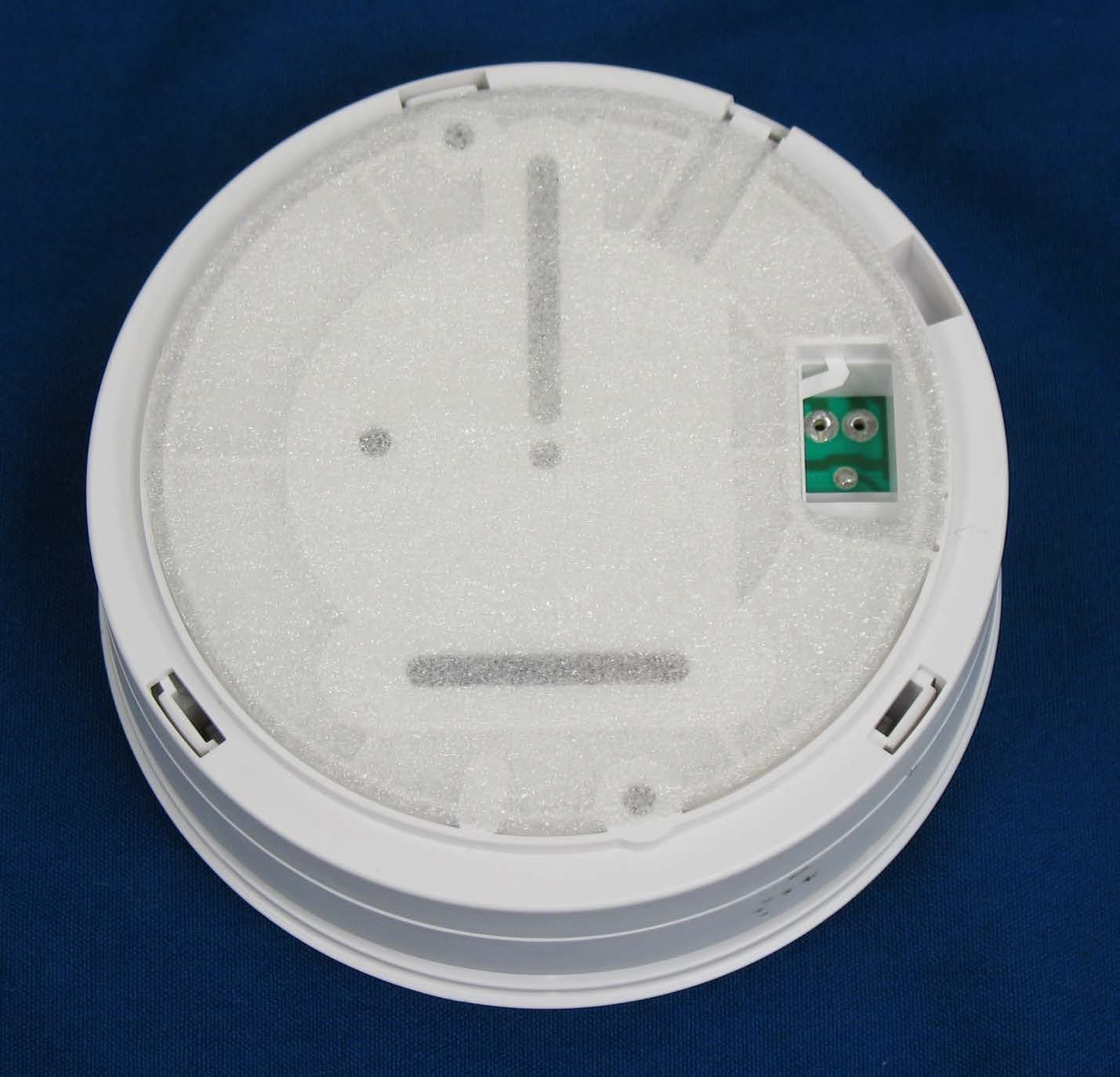
WMSBETXSA2
Aug 18, 2015BE1281 Optical Smoke Alarm Transmitter
Equipment Class
DSC - Part 15 Security/Remote Control Transmitter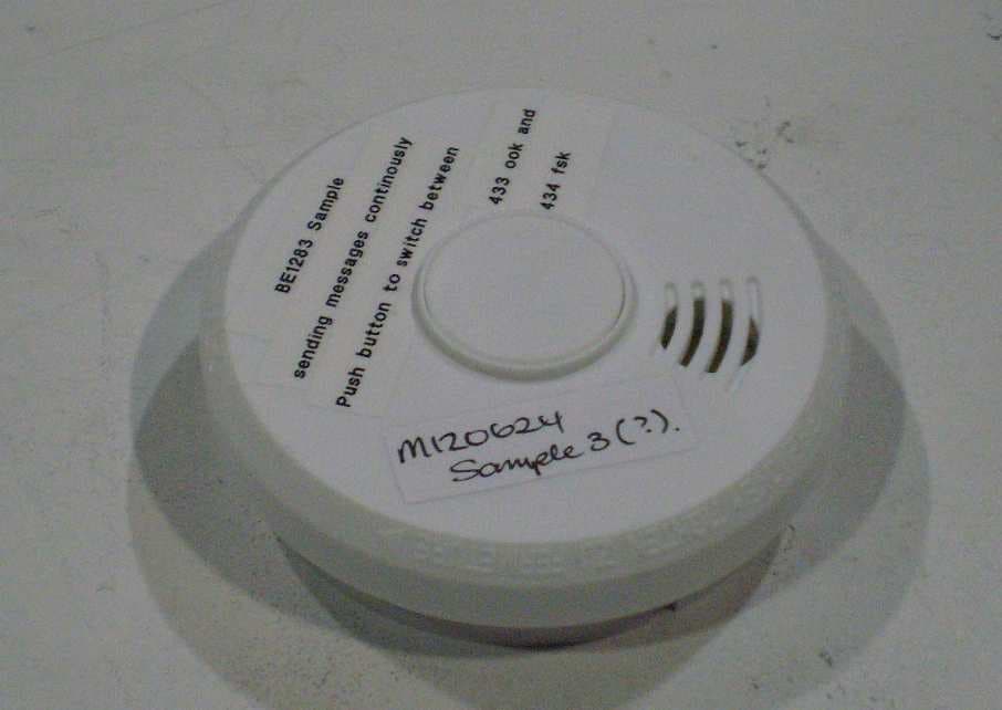
WMSBETXSA
Dec 10, 2012BE1283 OPTICAL SMOKE ALARM
Equipment Class
DSC - Part 15 Security/Remote Control Transmitter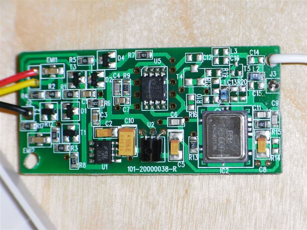
WMSBETX1
May 11, 2010Optical Smoke Alarm
Equipment Class
DSC - Part 15 Security/Remote Control Transmitter