WS312WA2BC00Multimedia Projector
SANYO Electronics (Dongguan) Co., Ltd.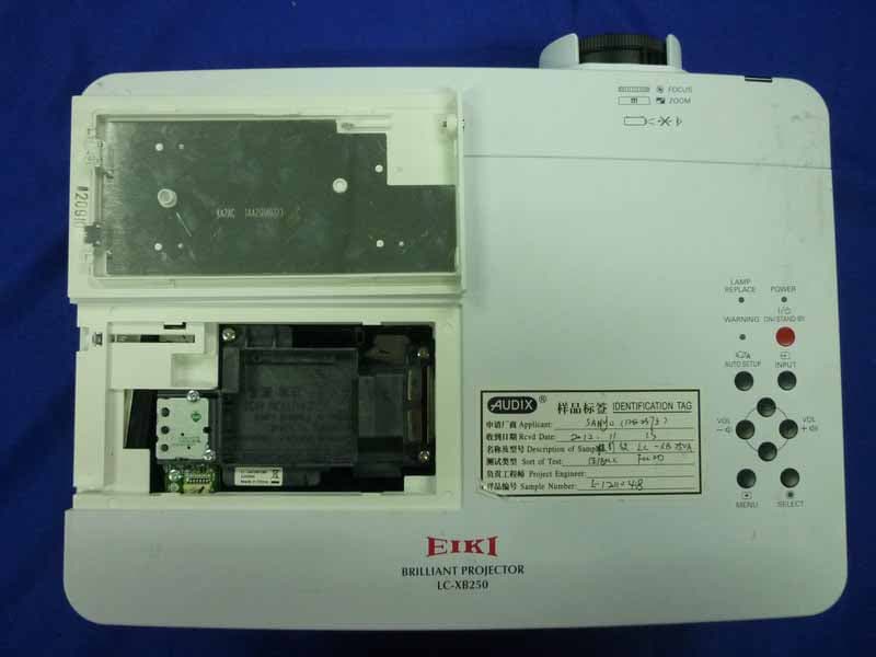
Click to zoom
Application Details
- Equipment Class
- JBP - Part 15 Class B Computing Device Peripheral
- Date of Grant
- Dec 12, 2012
- Application Purpose
- Original Equipment
- Date of Application
- Dec 11, 2012
- Equipment Note
- Multimedia Projector
- Country
- China
Documents & Files
Document Text
Text extracted from the exhibit documents filed with the FCC. Open a document above to read the original.
Users Manual
Owner's Manual Multimedia Projector MODEL LC-XB250A Network Supported Wired LAN Refer to the Owner's Manuals below for details about network function. Network Set-up and Operation PJ Network Manager 2 Features and Design This Multimedia Projector is designed with the most advanced technology for portability, durability, and ease of use. This projector utilizes built-in multimedia features, a palette of 16.77 million colors, and matrix liquid crystal display (LCD) technology. Compact Design This projector is designed compact in size and weight. It is easy to carry and installed anywhere you wish to use. Simple Computer System Setting The projector has the Multi-scan system to conform to almost all computer output signals quickly (p.29). Up to WUXGA resolution can be accepted. Useful Functions for Presentations - The digital zoom function allows you to focus on the crucial information during a presentation (p.36). - Blackboards* can be used as a projection screen. *The board color is limited to Green (pp.33, 41). Lamp Control Brightness of the projection lamp can be selected (pp.25, 54). Direct OFF Function With the Direct OFF function, you can disconnect the power cord from the wall outlet or turn off the breaker even during projection (p.20). Logo Function The Logo function allows you to customize the screen logo (pp.48-50). You can capture an image for the screen logo and use it for the starting-up display or between presentations. Multilanguage Menu Display Operation menu is available in 21 languages: English, German, French, Italian, Spanish, Portuguese, Dutch, Swedish, Finnish, Polish, Hungarian, Romanian, Czech, Russian, Turkish, Kazakh, Vietnamese, Chinese, Korean, Japanese and Thai (p.46). Note: • The On-Screen Menu and figures in this manual may differ slightly from the product. • The contents of this manual are subject to change without notice. Security Function The Security function helps you to ensure security of the projector. With the Key lock function, you can lock the operation on the top control or remote control (p.55). PIN code lock function prevents unauthorized use of the projector (pp.19, 55–56). Helpful Maintenance Functions Lamp and filter maintenance functions provide for better and proper maintenance of the projector. LAN Network Function This projector is loaded with the Wired LAN network function. You can operate and manage the projector via network. For details, refer to the owner’s manual “Network Set-up and Operation.” Auto Setup Function This function enables Input search, Auto Keystone correction and Auto PC adjustment by simple pressing the AUTO SETUP button on the top control (p.47). Colorboard Function At the time of simple projection on the colored wall, you can get the close color image to the color image projected on a white screen by selecting the similar color to the wall color from the preset four colors. Power Management The Power management function reduces power consumption and maintains the lamp life (p.51). Closed caption Closed caption is a function that displays the audio portion of a TV program as text on the screen. The closed captioning service is available mainly in the U.S (p.53). 3 Table of Contents Trademarks Each name of corporations or products in this book is either a registered trademark or a trademark of its respective corporation. Features and Design . . . . . . . . . . . . . . . . . . .2 Table of Contents . . . . . . . . . . . . . . . . . . . . . .3 To the Owner . . . . . . . . . . . . . . . . . . . . . . . . . .4 Safety Instructions . . . . . . . . . . . . . . . . . . . . .5 Air Circulation 6 Installing the Projector in Proper 6 Position 6 Moving the Projector 6 Compliance . . . . . . . . . . . . . . . . . . . . . . . . . . .7 Part Names and Functions . . . . . . . . . . . . . .8 Front 8 Back 8 Bottom 8 Rear Terminal 9 Top Control 10 Remote Control 11 Remote Control Battery Installation 12 Remote Control Operating Range 12 Remote Control Code 12 Installation . . . . . . . . . . . . . . . . . . . . . . . . . . .13 Positioning the Projector 13 Adjustable Feet 13 Connecting to a Computer 14 Connecting to Video Equipment 15 Connecting to Component Video Equipment 16 Connecting the AC Power Cord 17 Basic Operation . . . . . . . . . . . . . . . . . . . . . .18 Turning On the Projector 18 Turning Off the Projector 20 How to Operate the On-Screen Menu 21 Main Menu 22 Zoom and Focus Adjustment 23 Auto Setup Function 23 Keystone Correction 23 Sound Adjustment 24 Remote Control Operation 25 Computer Input . . . . . . . . . . . . . . . . . . . . . .27 Input Source Selection {(RGB: Computer 1/Computer 2(Analog)} 27 Input Source Selection {Computer 2: RGB(PC digital), RGB(AV HDCP)} 28 Computer System Selection 29 Auto PC Adjustment 30 Manual PC Adjustment 31 Image Mode Selection 33 Image Adjustment 34 Screen Size Adjustment 35 Video Input . . . . . . . . . . . . . . . . . . . . . . . . . .38 Input Source Selection (Video, S-video) 38 Input Source Selection (Component, Scart) 39 Video System Selection 40 Image Mode Selection 41 Image Adjustment 42 Screen Size Adjustment 44 Setting . . . . . . . . . . . . . . . . . . . . . . . . . . . . . .46 Setting 46 Information . . . . . . . . . . . . . . . . . . . . . . . . . .59 Input Source Information Display 59 Maintenance and Cleaning . . . . . . . . . . . . .60 WARNING indicator 60 Replacing the Filters 61 Resetting the Filter Counter 61 Attaching the Lens Cap 62 Cleaning the Projection Lens 62 Cleaning the Projector Cabinet 62 Lamp Replacement 63 Appendix . . . . . . . . . . . . . . . . . . . . . . . . . . .65 Troubleshooting 65 Menu Tree 68 Indicators and Projector Condition 70 Compatible Computer Specifications 71 Technical Specifications 73 Optional Parts 74 PJ Link Notice 75 Attaching the Filter Cover to the projector 75 Configurations of Terminals 76 PIN Code Number Memo 77 Dimensions 78 4 To the Owner CAUTION: TO REDUCE THE RISK OF ELECTRIC SHOCK, DO NOT …
Text truncated - open the document above for the full version.
Users Manual
34 Image adjust Menu Image Adjustment Reset Press the MENU button to display the On-Screen Menu. Use the Point ▲▼ buttons to select Image adjust and then press the Point ► or the SELECT button. 1 2 Use the Point ▲▼ buttons to select the desired item and then press the SELECT button to display the adjustment dialog box. Use the Point ◄► buttons to adjust the setting value. Note: • When White balance Red, Green or Blue is adjusted, Color temp . will change to User. • When Blackboard(Green) or Colorboard is selected in Image select, Color temp . will change to Blackboard or Colorboard. Press the Point ◄ button to decrease the contrast; press the Point ► button to increase the contrast (from 0 to 63). Press the Point ◄ button to decrease the brightness; press the Point ► button to increase the brightness (from 0 to 63). Contrast Brightness Press the Point ◄ button to lighten R/G/B tone; press the Point ► button to deepen R/G/B tone (from 0 to 63). white balance (Red/Green/Blue) Use the Point ◄► buttons to select the desired Color temp. level (XLow, Low, Mid or High). Color temp . Use the Point ◄► buttons to adjust the gamma value to obtain a better balance of contrast (from 0 to 15). Gamma Press the Point ◄ button to decrease the sharpness of the image; press the Point ► button to increase the sharpness of the image (from 0 to 15). Sharpness To reset the adjusted data, select Reset and press the SELECT button. A confirmation box appears and then select yes. All adjustments will return to their previous figures. Use the Point ◄► buttons to adjust the setting value. Selected Image mode Computer Input 35 This projector has the picture screen resize function, which enables you to customize the image size. Screen Menu Screen Size Adjustment Provide the image to fit the screen size. Normal Full Provide the full screen image. Note: • This projector cannot display any resolution higher than 1920 x 1200. If your computer’s screen resolution is higher than it, reset the resolution lower before connecting to the projector. • The image data in other than 1024 x 768 is modified to fit the screen size in initial mode. • True and Digital zoom +/– cannot be selected when 480i, 575i, 480p, 575p, 720p, 1035i or 1080i is selected in the PC System Menu (p.29). 1 2 Press the MENU button to display the On-Screen Menu. Use the Point ▲▼ buttons to select Screen and then press the Point ► or the SELECT button. Use the Point ▲▼ buttons to select the desired item and then press the SELECT button . Computer Input wide (16:9) Provide the image at the 16:9 wide screen ratio. Zoom Scale the image proportionally to fit the entire screen. Either side of image may go over the screen. Custom Provide the last stored aspect screen image. Store To store the adjusted data, select Store and press the Point ► button or the SELECT button. Use the Point ▲▼ buttons to select one from Image 1 to 4 and press the SELECT button. A confirmation box appears and then select yes. Stored data can be called up by selecting an Image (1–4) in the Image Mode Selection on page 33. True Provide the image in its original size. When the original image size is larger than the screen size (1024 x 768), the projector enters to the panning mode automatically. Use the Point ▲▼◄► buttons to pan the image. When adjusted, the arrows will turn red. When reached to the correction limits, the arrows will disappear. A confirmation box appears and then select yes. 36 Select Digital zoom +. The On-Screen Menu disappears and D . zoom + appears. Press the SELECT button to expand the image size. Use the Point ▲▼◄► buttons to pan the image. The Panning function can work only when the image is larger than the screen size. A projected image can be also expanded by pressing the D.ZOOM ▲ or the SELECT button on the remote control. To exit the Digital zoom +/– mode, press any button except the D.ZOOM ▲▼ buttons and the SELECT button. Digital zoom + Select Digital zoom –. The On-Screen Menu disappears and D . zoom – appears. Press the SELECT button to compress image size. The projected image can be also compressed by pressing the D.ZOOM ▼ or the SELECT button on the remote control. Digital zoom – To return to the previous screen size, select a screen size from the Screen Size Adjustment Menu or select an input source from the Input Source Selection Menu (pp.27-28) again, or adjust the screen size with the D.ZOOM ▲▼ buttons. Remote Control D .ZOOM ▲ button POINT ▲▼◄► buttons SELECT button D .ZOOM ▼button Computer Input Computer Input Adjust the screen scale and position manually with this function. Press the Point ► button at Custom and the Custom is displayed on the screen, you can use the Point ▲▼ buttons to choose the item you want to adjust. Scale H/V .......... Adjust the Horizontal/Vertical screen scale. H&V ................... When set to On, the aspect ratio is fixed. The Scale V appears dimmed and becomes unavailable. Adjust Scale H, then the screen scale is automatically modified based on the aspect ratio. Position H/V ..... Adjust the Horizontal/Vertical screen position. Common ........... Save the adjusted scale or position to all the inputs. Press the SELECT button at Common to display a confirmation box. To save the scale or position, press the SELECT button at yes. When Custom is selected, the saved scale or position is used. Reset ................. Reset all the adjusted values. Press the SELECT button at Reset to display a confirmation box. To reset, press the SELECT button at yes. Custom adj . Note: • When no signal is detected, Normal is set automatically and the Aspect dialog box disappears. • The adjustable range for Scale H/V and Position H/V is limited depending on the input signal. Note: • The minimum compression ratio is limited depending on the input signal, when the Keystone function is working or when the custom is selected for the screen size. • True and Digital zoom +/– are disabled and cannot be displayed when 480i, 575i, 480p 575p, 720p,…
Text truncated - open the document above for the full version.
External Photos
R AUDIX Technology (Shenzhen) Co., Ltd. FCC ID:WS312WA2BC00 page Audix Technology (Shenzhen) Co., Ltd. Report No. ACS-F12259 7-1 7. PHOTOS OF THE EUT Figure 1 General Appearance of the EUT Figure 2 General Appearance of the EUT R AUDIX Technology (Shenzhen) Co., Ltd. FCC ID:WS312WA2BC00 page Audix Technology (Shenzhen) Co., Ltd. Report No. ACS-F12259 7-2 Figure 3 General Appearance of the EUT Figure 4 General Appearance of the EUT R AUDIX Technology (Shenzhen) Co., Ltd. FCC ID:WS312WA2BC00 page Audix Technology (Shenzhen) Co., Ltd. Report No. ACS-F12259 7-3 Figure 5 General Appearance of the EUT Figure 6 General Appearance of the EUT
ID Label/Location Info
Label Location
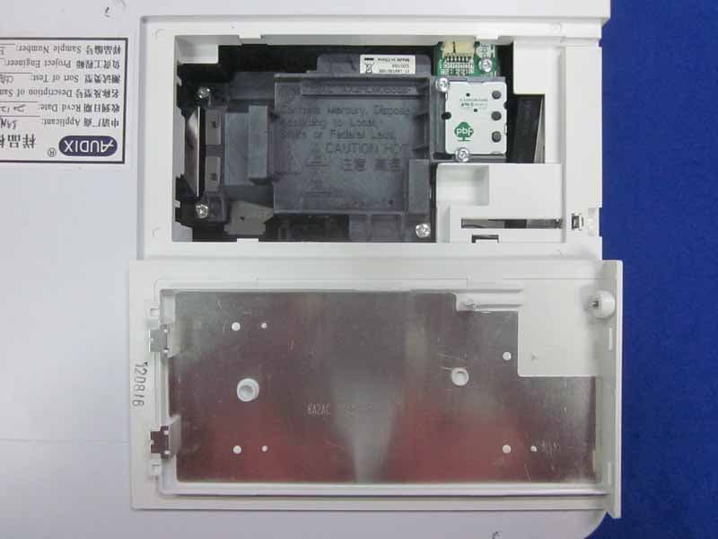
Internal Photos
R AUDIX Technology (Shenzhen) Co., Ltd. FCC ID:WS312WA2BC00 page Audix Technology (Shenzhen) Co., Ltd. Report No. ACS-F12259 7-4 Figure 7 Inside of the EUT Figure 8 Inside of the EUT R AUDIX Technology (Shenzhen) Co., Ltd. FCC ID:WS312WA2BC00 page Audix Technology (Shenzhen) Co., Ltd. Report No. ACS-F12259 7-5 Figure 9 Inside of the EUT Figure 10 Inside of the EUT R AUDIX Technology (Shenzhen) Co., Ltd. FCC ID:WS312WA2BC00 page Audix Technology (Shenzhen) Co., Ltd. Report No. ACS-F12259 7-6 Figure 11 Inside of the EUT Figure 12 Inside of the EUT R AUDIX Technology (Shenzhen) Co., Ltd. FCC ID:WS312WA2BC00 page Audix Technology (Shenzhen) Co., Ltd. Report No. ACS-F12259 7-7 Figure 13 Inside of the EUT Figure 14 Inside of the EUT R AUDIX Technology (Shenzhen) Co., Ltd. FCC ID:WS312WA2BC00 page Audix Technology (Shenzhen) Co., Ltd. Report No. ACS-F12259 7-8 Figure 15 Inside of the EUT Figure 16 Inside of the EUT R AUDIX Technology (Shenzhen) Co., Ltd. FCC ID:WS312WA2BC00 page Audix Technology (Shenzhen) Co., Ltd. Report No. ACS-F12259 7-9 Figure 17 Inside of the EUT Figure 18 Inside of the EUT R AUDIX Technology (Shenzhen) Co., Ltd. FCC ID:WS312WA2BC00 page Audix Technology (Shenzhen) Co., Ltd. Report No. ACS-F12259 7-10 Figure 19 Inside of the EUT Figure 20 Inside of the EUT R AUDIX Technology (Shenzhen) Co., Ltd. FCC ID:WS312WA2BC00 page Audix Technology (Shenzhen) Co., Ltd. Report No. ACS-F12259 7-11 Figure 21 Inside of the EUT Figure 22 Inside of the EUT R AUDIX Technology (Shenzhen) Co., Ltd. FCC ID:WS312WA2BC00 page Audix Technology (Shenzhen) Co., Ltd. Report No. ACS-F12259 7-12 Figure 23 Inside of the EUT Figure 24 Inside of the EUT R AUDIX Technology (Shenzhen) Co., Ltd. FCC ID:WS312WA2BC00 page Audix Technology (Shenzhen) Co., Ltd. Report No. ACS-F12259 7-13 Figure 25 Inside of the EUT Figure 26 Inside of the EUT R AUDIX Technology (Shenzhen) Co., Ltd. FCC ID:WS312WA2BC00 page Audix Technology (Shenzhen) Co., Ltd. Report No. ACS-F12259 7-14 Figure 27 Inside of the EUT Figure 28 Inside of the EUT R AUDIX Technology (Shenzhen) Co., Ltd. FCC ID:WS312WA2BC00 page Audix Technology (Shenzhen) Co., Ltd. Report No. ACS-F12259 7-15 Figure 29 Inside of the EUT Figure 30 Inside of the EUT R AUDIX Technology (Shenzhen) Co., Ltd. FCC ID:WS312WA2BC00 page Audix Technology (Shenzhen) Co., Ltd. Report No. ACS-F12259 7-16 Figure 31 Inside of the EUT Figure 32 Inside of the EUT R AUDIX Technology (Shenzhen) Co., Ltd. FCC ID:WS312WA2BC00 page Audix Technology (Shenzhen) Co., Ltd. Report No. ACS-F12259 7-17 Figure 33 Inside of the EUT Figure 34 Inside of the EUT R AUDIX Technology (Shenzhen) Co., Ltd. FCC ID:WS312WA2BC00 page Audix Technology (Shenzhen) Co., Ltd. Report No. ACS-F12259 7-18 Figure 35 Inside of the EUT Figure 36 Inside of the EUT R AUDIX Technology (Shenzhen) Co., Ltd. FCC ID:WS312WA2BC00 page Audix Technology (Shenzhen) Co., Ltd. Report No. ACS-F12259 7-19 Figure 37 Inside of the EUT Figure 38 Remote Controller R AUDIX Technology (Shenzhen) Co., Ltd. FCC ID:WS312WA2BC00 page Audix Technology (Shenzhen) Co., Ltd. Report No. ACS-F12259 7-20 Figure 39 VGA Cable
Test Report
R AUDIX Technology (Shenzhen) Co., Ltd. FCC ID:WS312WA2BC00 Audix Technology (Shenzhen) Co., Ltd. Report No. ACS-F12259 APPLICATION FOR CERTIFICATION On Behalf of SANYO Electronics (Dongguan) CO., LTD. Multimedia Projector Model No.: LC-XB250A FCC ID: WS312WA2BC00 Prepared for : SANYO Electronics (Dongguan) CO., LTD. Hong Ye Industry Area, TangXia Town, DongGuan City, Guangdong Prov., China Prepared By : Audix Technology (Shenzhen) Co., Ltd. No. 6, Ke Feng Rd., 52 Block, Shenzhen Science & Industrial Park, Nantou, Shenzhen, Guangdong, China Tel: (0755) 26639496 Report Number : ACS-F12259 Date of Test : Nov.14~29, 2011 Date of Report : Dec.03, 2011 R AUDIX Technology (Shenzhen) Co., Ltd. FCC ID:WS312WA2BC00 Audix Technology (Shenzhen) Co., Ltd. Report No. ACS-F12259 TABLE OF CONTENTS Description Page 1. SUMMARY OF STANDARDS AND RESULTS .................................................................. 1-1 1.1. Description of Standards and Results.............................................................................................1-1 2. GENERAL INFORMATION .................................................................................................. 2-1 2.1. Description of Device (EUT) .........................................................................................................2-1 2.2. Tested Supporting System Details .................................................................................................2-2 2.3. Block Diagram of connection between EUT and simulators .........................................................2-3 2.4. Test Facility....................................................................................................................................2-4 2.5. Test Uncertainty (95% confidence levels, k=2) .............................................................................2-4 3. POWER LINE CONDUCTED EMISSION TEST................................................................ 3-1 3.1. Test Equipments.............................................................................................................................3-1 3.2. Block Diagram of Test Setup .........................................................................................................3-1 3.3. Power Line Conducted Emission Test Limits ................................................................................3-1 3.4. Configuration of EUT on Test .......................................................................................................3-1 3.5. Operating Condition of EUT..........................................................................................................3-2 3.6. Test Procedure................................................................................................................................3-2 3.7. Power Line Conducted Emission Test Results...............................................................................3-2 4. RADIATED EMISSION TEST ............................................................................................... 4-1 4.1. Test Equipment ..............................................................................................................................4-1 4.2. Block Diagram of Test Setup .........................................................................................................4-1 4.3. Radiated Emission Limit ................................................................................................................4-2 4.4. EUT Configuration on Test............................................................................................................4-2 4.5. Operating Condition of EUT..........................................................................................................4-2 4.6. Test Procedure................................................................................................................................4-3 4.7. Radiated Emission Test Results .....................................................................................................4-3 5. DEVIATION TO TEST SPECIFICATIONS ........................................................................ 5-1 6. PHOTOGRAPH OF TEST...................................................................................................... 6-1 6.1. Photos of Power Line Conducted Emission Test ...........................................................................6-1 6.2. Photos of Radiated Emission Test for 30~1000MHz.....................................................................6-2 6.3. Photos of Radiated Emission Test for above 1GHz .......................................................................6-3 7. PHOTOS OF THE EUT........................................................................................................... 7-1 R AUDIX Technology (Shenzhen) Co., Ltd. FCC ID:WS312WA2BC00 Page Audix Technology (Shenzhen) Co., Ltd. Report No. ACS-F12259 1-1 1. SUMMARY OF STANDARDS AND RESULTS 1.1. Description of Standards and Results The EUT have been tested according to the applicable standards as referenced below. EMISSION Description of Test Item Standard Limits Results Power Line Conducted Emission Test FCC Part 15: 2011 ANSI C63.4: 2009 Class B PASS Radiated Emission Test FCC Part 15: 2011 ANSI C63.4: 2009 Class B PASS R AUDIX Technology (Shenzhen) Co., Ltd. FCC ID:WS312WA2BC00 Page Audix Technology (Shenzhen) Co., Ltd. Report No. ACS-F12259 2-1 2. GENERAL INFORMATION 2.1. Description of Device (EUT) Description : Multimedia Projector Model Number : LC-XB250A Remote Controller : Manufacturer: EIKI, M/N: CXZS Max Work Frequency : 180MHz Applicant : SANYO Electronics (Dongguan) CO., LTD. Hong Ye industry Area, Tang Xia Town, Dong Guan City, Guang Dong Prov, CHINA Manufacturer : Panasonic Corporation 2-15, Matsuba-cho, Kadoma-City, Osaka, 571-8503, JAPAN Factory : SANYO Electronics (Dongguan) CO., LTD. Hong Ye industry Area, Tang Xia Town, Dong Guan Cit…
Text truncated - open the document above for the full version.
Test Setup Photos
R AUDIX Technology (Shenzhen) Co., Ltd. FCC ID:WS312WA2BC00 Page 6-1 Audix Technology (Shenzhen) Co., Ltd. Report No. ACS-F12259 6. PHOTOGRAPH OF TEST 6.1. Photos of Power Line Conducted Emission Test R AUDIX Technology (Shenzhen) Co., Ltd. FCC ID:WS312WA2BC00 Page 6-2 Audix Technology (Shenzhen) Co., Ltd. Report No. ACS-F12259 6.2. Photos of Radiated Emission Test for 30~1000MHz R AUDIX Technology (Shenzhen) Co., Ltd. FCC ID:WS312WA2BC00 Page 6-3 Audix Technology (Shenzhen) Co., Ltd. Report No. ACS-F12259 6.3. Photos of Radiated Emission Test for above 1GHz
Contact Information
Applicant
Zhao Yan(Technician)
Technical Contact
AUDIX Technology (Shenzhen) Co., Ltd.Sunny Lu
[email protected]86-755-26639497
52 Block Shenzhen Science & Industry. · Shenzhen · China
Test Firm
Audix Technology (Shenzhen) Co.Smart Tsai
Technical Specifications
| # | Rule Parts | Frequency Range | Power Output |
|---|---|---|---|
| 1 | 15B | - | - |
Other Applications from SANYO Electronics (Dongguan) Co., Ltd.
WS312WB2BC00
Dec 12, 2012Multimedia Projector
Equipment Class
JBP - Part 15 Class B Computing Device Peripheral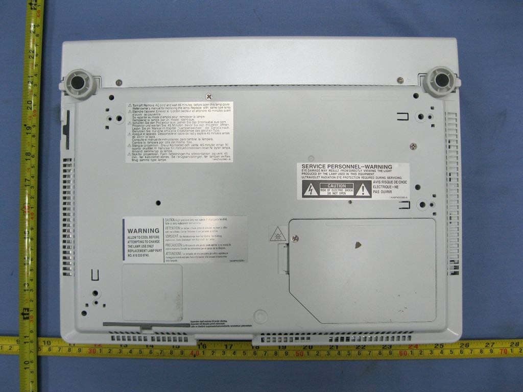
WS311KY7AF00
Jun 07, 2011Multimedia Projector
Equipment Class
JBP - Part 15 Class B Computing Device Peripheral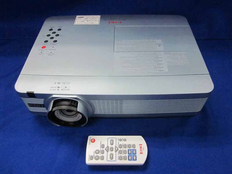
WS311KC2AC00
May 31, 2011LCD Projector
Equipment Class
JBP - Part 15 Class B Computing Device Peripheral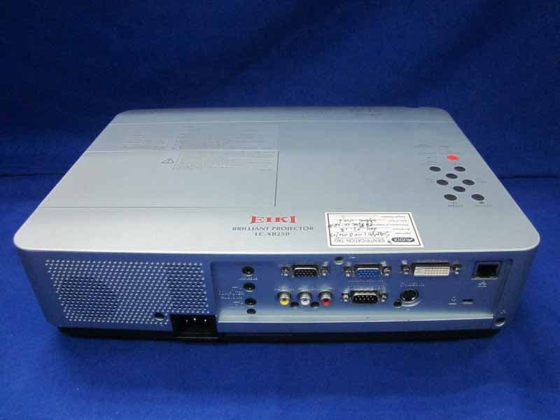
WS311KA2BC00
May 25, 2011LCD Projector
Equipment Class
JBP - Part 15 Class B Computing Device Peripheral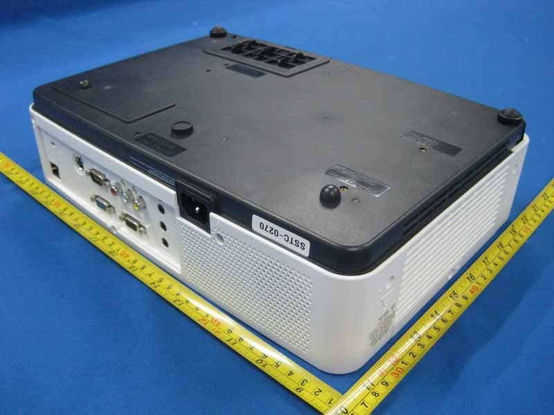
WS310KA2AC00
Dec 05, 2010LCD Projector
Equipment Class
JBP - Part 15 Class B Computing Device Peripheral