WUI-BT532767CAMWIFI
Winplus Co., Ltd.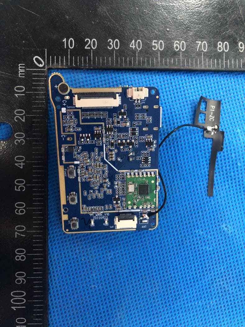
Click to zoom
Application Details
- Equipment Class
- DTS - Digital Transmission System
- Date of Grant
- Jun 19, 2022
- Application Purpose
- Original Equipment
- Date of Application
- Jun 19, 2022
- Equipment Note
- CAMWIFI
- Frequency Range
- 2412.00000000 - 2462.00000000
- Company
- Winplus Co., Ltd.
- Country
- Hong Kong
Documents & Files
Document Text
Text extracted from the exhibit documents filed with the FCC. Open a document above to read the original.
Users Manual
WiFi Module CDW- B18189F-Q1 1. Overview The CDW-B18189F-02 is a highly integrated WI-F I single chip which supports 72.2Mbps PHY rate. It fully complies with IEEE 802.11n and IEEE 802.11b/g standards, offering feature-rich wireless connectivity at high standards, and delivering reliable, cost-effective though put from an extended distance. Optimized RF architecture and baseband algorithms provide superb performance and low power consumption .Intelligent MAC design deploys a high efficient DMA engine and hardware data processing accelerators which offloads the host processor. The CDW-B18189F-02 is designed to support standard based features in the areas of security, quality of service and international regulations, giving end users the greatest performance any time and in any circumstance. 2.Features ■ IEEE 802.11b/g/n ■ Embedded high-performance 32-bit RISC microprocessor ■Hi ghly integrated RF with 55nm CMOS technology ■1T1R mode with support of 72.2Mbps PHY rate ■Integrate high efficiency switching regulator ■Best –in-class power consumption performance ■802.11d/h/k compliant ■Security support for WGA WPA/WPA2 personal,WPS2.0,WAPI ■Supp orts 802.11n protected managed frames ■Qo S support of WFA WMM,WMM PS ■Supports Wi-Fi Direct ■Fully compliance with SDIO 2.0 High-speed mode Page 2 WiFi Module CDW- B18189F-Q1 3.General Specification Model CDW-B18189F-02 Product Name CAMWIFI Major Chipset RTL8189FTV-VC-CG Standard 802.11b/g/n, 802.3, 802.3u Data Transfer Rate 1,2,5.5,6,11,12,18,22,24,30,36,48,54,60,90,120 and maximum of 72.2Mbps Modulation Method BPSK/ QPSK/ 16-QAM/ 64-QAM Frequency Band 2.4~2.4835 GHz ISM Band Spread Spectrum IEEE 802.11b: DSSS (Direct Sequence Spread Spectrum)IEEE802.11g/n:OFDM(OrthogonalFrequency Division Multiplexing) RF Output Power 11n > 12dBm,11g > 13dBm,11b > 16dBm Operation Mode Ad hoc, Infrastructure Receiver Sensitivity 11b CCK11(PER<8%) < -85dBm , 11g OFDM54(PER<10%) < -73dBm , 11n HT20 MCS7(PER<10%) < -69dBm Operation Range Up to 180 meters in open space OS Support Windows2000,XP32-64,Vista32/64,Win732/64, Linux, Mac, Android,WIN CE Security WEP, TKIP, AES, WPA, WPA2 Interface SDIO2.0 Power Consumption DC3.3V 600mA Operating Temperature 0~ +70°C ambient temperature Storage Temperature -20 ~ 125°C ambient temperature Humidity 5 to 90 % maximum (non-condensing) Dimension 14.1 x 12.5 x0.6 mm (LxW) ±0.15mm Page 3 WiFi Module CDW- B18189F-Q1 4. DC Characteristics Description TYP Unit Sleep mode 1.5 mA RX Active,HT40,MCS7 220 mA RX Power saving, DTIM=1 20 mA RX Listen 10 mA TX HT40,mcs7 @13dBm 230 mA TX CCK,11Mbps @17dBm 280 mA No te: All result is measured at the antenna port and VDD33 is 3.3V,3.3V Rating Current 600mA. 5. Pin Description and PCB size Page 4 WiFi Module CDW- B18189F-Q1 NO. Name Description 1 SD_CMD SDIO Command Input 2 SD_D3 SDIO Data Line 3 3 SD_D2 SDIO Data Line 2 4 SD_D1 SDIO Data Line 1 5 SD_D0 SDIO Data Line 0 6 SD_CLK SDIO Clock Input 7 GND Ground 8 GND Ground 9 ANT WIFI radio antenna, Impedence control to 50oh 10 WAKE WIFI WAKE Device 11 VDIO VDD for SDIO Pin. The power supply is the same as the signal level of SDIO bus(3.3V ~ 1.8V) 12 VDD33 Power supply 3.3V 13 CS This pin can Externally Shutdown theRTL8189FTVwithoutrequiring an extra power switch 14,15 GND Ground 16,17 GND Ground , no connect Page 5 WiFi Module CDW- B18189F-Q1 6.Recommended Reflow Profile Ref erred IPC/JEDEC standard. Peak Temperature : <250°C Number of Times : 2 times Page 6 WiFi Module CDW- B18189F-Q1 7.Packing information ESD CAUTION The CDW-B18189F-02 is ESD (electrostatic discharge) sensitive device and may be damaged with ESD or spike voltage. Although CDW-B18189F-02 is with built-in ESD protection circuitry, please handle with care to avoid the permanent malfunction or t he performance degradatio n. Page 7 FCC Statement This device complies with part 15 of the FCC Rules. Operation is subject to the following two conditions: (1) This device may not cause harmful interference, and (2) this device must accept any interference received, including interference that may cause undesired operation. Any Changes or modifications not expressly approved by the party responsible for compliance could void the user's authority to operate the equipment. Note:This equipment has been tested and found to comply with the limits for a Class B digital device, pursuant to part 15 of the FCC Rules. These limits are designed to provide reasonable protection against harmful interference in a residential installation. This equipment generates uses and can radiate radio frequency energy and, if not installed and used in accordance with the instructions, may cause harmful interference to radio communications.However, there is no guarantee that interference will not occur in a particular installation. If this equipment does cause harmful interference to radio or television reception, which can be determined by turning the equipment off and on, the user is encouraged to try to correct the interference by one or more of the following measures: -Reorient or relocate the receiving antenna. -Increase the separation between the equipment and receiver. -Connect the equipment into an outlet on a circuit different from that to which the receiver is connected. -Consult the dealer or an experienced radio/TV technician for help. The CAMWIFI is designed to comply with the FCC statement. FCC ID is WUI-BT532767. The host system using CAMWIFI Module, should have label indicated it contain modular’s FCC ID: WUI-BT532767 . This radio module must not installed to colocate and operating simultaneously with other radios in host system additional testing and equipment authorization may be required to operating simultaneously with other radio. The CAMWIFI is deaigned for a compact PCB design .It should be installed and operated with Dash Cam or other minimum distance of 20 centimeters between the radiator and your body." To comply with FCC regulations limiting both maximum RF output power and human exposure to RF r…
Text truncated - open the document above for the full version.
Cover Letter(s)
THIS MUST BE SIGNED BY THE APPLICANT/AGENT AND SHOULD BE PLACED ON APPROPRIATE LETTERHEAD Request for Modular/Limited Modular Approval Date: June 17, 2022 Subject: Manufacturer’s Declaration for ☐ - Modular Approval ☐ - Split Modular Approval ☒ - Limited Modular Approval ☐ - Limited Split Modular Approval Confidentiality Request for: ______WUI-BT532767_____ 8 Basic Requirements – FCC Part 15.212(a)(1) For Items Marked “NO(*)”, the Limited Module Description Must be Filled Out on the Following Pages Modular Approval Requirement Requirement Met 1. The modular transmitter must have its own RF shielding. This is intended to ensure that the module does not have to rely upon the shielding provided by the device into which it is installed in order for all modular transmitter emissions to comply with FCC limits. It is also intended to prevent coupling between the RF circuitry of the module and any wires or circuits in the device into which the module is installed. Such coupling may result in non-compliant operation. The physical crystal and tuning capacitors may be located external to the shielded radio elements. 15.212(a)(1)(i) ☐ - YES ☒ - NO(*) The product has no metal shielding shell 2. The modular transmitter must have buffered modulation/data inputs (if such inputs are provided) to ensure that the module will comply with FCC requirements under conditions of excessive data rates or over-modulation. 15.212(a)(1)(ii) ☒ - YES ☐ - NO(*) 3. The modular transmitter must have its own power supply regulation on the module. This is intended to ensure that the module will comply with FCC requirements regardless of the design of the power supplying circuitry in the device into which the module is installed. 15.212(a)(1)(iii) ☒ - YES ☐ - NO(*) 4. The modular transmitter must comply with the antenna and transmission system requirements of §§ 15.203, 15.204(b), 15.204(c), 15.212(a), and 2.929(b). The antenna must either be permanently attached or employ a ‘‘unique’’ antenna coupler (at all connections between the module and the antenna, including the cable). The ‘‘professional installation’’ provision of § 15.203 is not applicable to modules but can apply to limited modular approvals under paragraph 15.212(b). 15.212(a)(1)(iv) ☐ - YES ☒ - NO(*) The product has no fixed antenna or standard antenna port 5. The modular transmitter must be tested in a stand-alone configuration, i.e., the module must not be inside another device during testing. This is intended to demonstrate that the module is capable of complying with Part 15 emission limits regardless of the device into which it is eventually installed. Unless the transmitter module will be battery powered, it must comply with the AC line conducted requirements found in Section 15.207. AC or DC power lines and data input/output lines connected to the module must not contain ferrites, unless they will be marketed with the module (see Section 15.27(a)). The length of these lines shall be length typical of actual use or, if that length is unknown, at least 10 centimeters to insure that there is no coupling between the case of the module and supporting equipment. Any accessories, peripherals, or support equipment connected to the module during testing shall be unmodified or commercially available (see Section 15.31(i)). 15.212(a)(1)(v) ☐ - YES ☒ - NO(*) The product needs to work with the host THIS MUST BE SIGNED BY THE APPLICANT/AGENT AND SHOULD BE PLACED ON APPROPRIATE LETTERHEAD Modular Approval Requirement Requirement Met 6. The modular transmitter must be labeled with its own FCC ID number, or use an electron display (see KDB Publication 784748). If using a permanently affixed label with its own FCC ID number, if the FCC ID is not visible when the module is installed inside another device, then the outside of the device into which the module is installed must also display a label referring to the enclosed module. This exterior label can use wording such as the following: “Contains Transmitter Module FCC ID: XYZMODEL1” or “Contains FCC ID: XYZMODEL1.” Any similar wording that expresses the same meaning may be used. The Grantee may either provide such a label, an example of which must be included in the application for equipment authorization, or, must provide adequate instructions along with the module which explain this requirement. In the latter case, a copy of these instructions must be included in the application for equipment authorization. If the modular transmitter uses an electronic display of the FCC identification number, the information must be readily accessible and visible on the modular transmitter or on the device in which it is installed. If the module is installed inside another device, then the outside of the device into which the module is installed must display a label referring to the enclosed module. This exterior label can use wording such as the following: “Contains FCC certified transmitter module(s).” Any similar wording that expresses the same meaning may be used. The user manual must include instructions on how to access the electronic display. A copy of these instructions must be included in the application for equipment authorization. 15.212(a)(1)(vi) ☒ - YES ☐ - NO(*) 7. The modular transmitter must comply with all specific rule or operating requirements applicable to the transmitter, including all the conditions provided in the integration instructions by the grantee. A copy of these instructions must be included in the application for equipment authorization. For example, there are very strict operational and timing requirements that must be met before a transmitter is authorized for operation under Section 15.231. For instance, data transmission is prohibited, except for operation under Section 15.231(e), in which case there are separate field strength level and timing requirements. Compliance with these requirements must be assured. 15.212(a)(1)(vii) ☒ - YES ☐ - NO(*) 8. The modular transmitter must comply with any applicab…
Text truncated - open the document above for the full version.
Cover Letter(s)
Winplus Co., Ltd. 2022-06-10 Eurofins Electrical and Electronic Testing NA, Inc. 914 West Patapsco Avenue Baltimore, MD 21230 RE: LETTER OF AGENT AUTHORIZATION To Whom It May Concern: We, the undersigned, hereby authorize DongGuan Anci Electronic Technology Co., Ltd. to act on our behalf in all matters relating to application for equipment authorization, including the signing of all documents relating to these matters. We also hereby certify that no party to the application authorized hereunder is subject to the denial of benefits, including FCC benefits, pursuant to Section 5301 of the Anti-Drug Abuse Act of 1988, 21 U.S.C.853(a). This agreement expires one year from the current date. Sincerely, Benson H Leung Director Winplus Co., Ltd. Suites 6-11, 7th Floor, Corporation Park, 11 On La, Shatin, Hong Kong
Cover Letter(s)
Winplus Co., Ltd. 2022-06-10 Eurofins Electrical and Electronic Testing NA, Inc. 914 West Patapsco Avenue Baltimore, MD 21230 RE: CONFIDENTIALITY REQUEST FOR (EUT Name: CAMWIFI /Model: BT532767 /FCC ID: WUI-BT532767) To Whom It May Concern: This letter serves as an official request for confidentiality under sections 0.457 and 0.459 of CFR 47. We have requested that the (Block Diagram ,Operational Description,Schematics) required to be submitted with this application be permanently withheld from public review. The above materials contain trade secrets and proprietary information not customarily released to the public. The public disclosure of these materials may be harmful to the applicant and provide unjustified benefits to its competitors. Please contact me if there is any information you may need. Sincerely, Benson H Leung Director Winplus Co., Ltd. Suites 6-11, 7th Floor, Corporation Park, 11 On La, Shatin, Hong Kong
External Photos
ANT
ID Label/Location Info
Silk screen CAMWIFI Model: BT532767 FCC ID: WUI-BT532767 Label Location
Internal Photos
ANT PORT
RF Exposure Info
RF EXPOSURE EVALUATION EUT Specification EUT CAMWIFI Model Number BT532767 FCC ID WUI-BT532767 Antenna gain (Max) 0 dBi Operation Frequency 2.412GHz ~ 2.462GHz Input Rating DC 12V, DC 24V for host Max. output power 802.11b: 10.46dBm 802.11g: 10.27dBm 802.11n(HT20): 9.71dBm 802.11n(HT40): 12.83dBm Test Requirement: According to FCC 1.1310: The criteria listed in the following table shall be used to evaluate the environment impact of human exposure to radio frequency(RF) Radiation as specified in §1.1307(b) Limits for Maximum Permissible Exposure (MPE) Frequency Range(MHz) Electric Field Strength(V/m) Magnetic Field Strength(A/m) Power Density(mW/cm 2 ) Average Time (A) Limits for Occupational/Control Exposures 300-1500 -- -- F/300 6 1500-100000 -- -- 5 6 (B) Limits for General Population/Uncontrol Exposures 300-1500 -- -- F/1500 6 1500-100000 -- -- 1 30 11.1 Friis transmission formula: Pd= (Pout*G)\ (4*pi*R 2 ) Where Pd= Power density in mW/cm 2 Pout=output power to antenna in mW G= Numeric gain of the antenna relative to isotropic antenna Pi=3.1416 R= 20cm distance between observation point and center of the radiator in cm Pd the limit of MPE, 1mW/cm 2 . If we know the maximum gain of the nd total power input to the antenna, through the calculation, we will know the distance where the MPE limit is reached. 11.2 Measurement Result Operation Mode Channel Number Channel Frequency (MHz) Measurement Level (dBm) Limit (dBm) Verdict Ant1 802.11b 1 2412 9.05 30 PASS 6 2437 9.68 30 PASS 11 2462 10.46 30 PASS 802.11g 1 2412 8.87 30 PASS 6 2437 9.79 30 PASS 11 2462 10.27 30 PASS 802.11n (HT20) 1 2412 8.89 30 PASS 6 2437 9.71 30 PASS 11 2462 8.25 30 PASS 802.11n (HT20) 3 2422 11.19 30 PASS 6 2437 11.99 30 PASS 9 2452 12.83 30 PASS 1 9±110 10.000010.001989 1 6 10±1 11 12.589010.002505 1 11 11±112 15.849010.003153 1 1 9±110 10.000010.001989 1 6 10±111 12.589010.002505 1 11 10±111 12.589010.002505 1 802.11n1 9±110 10.000010.001989 1 (HT20)6 10±111 12.589010.002505 1 11 8±19 7.943010.001580 1 802.11n3 11±1 12 15.849010.003153 1 (HT40)6 12±1 13 19.953010.003969 1 9 13±114 25.119010.004997 1 802.11b 802.11g Signature: Tomas Yang Date: 2022-06-10
Test Report
Report No.: E01A22030657F00701 1 of 62 DongGuan Anci Electronic Technology Co., Ltd 1-2 Floor, Building A, No.11, Headquarters 2 Road, Songshan Lake Hi-tech Industrial Development Zone, Dongguan City, Guangdong Pr., China. Phone: 86-769- 8507 5888; Fax: 86-769- 8507 5898 E-mail: [email protected] Rev. 1.0 ELECTROMAGNETIC EMISSIONS COMPLIANCE REPORT INTENTIONAL RADIATOR CERTIFICATION TO FCC PART 15 SUBPART C REQUIREMENT OF CAMWIFI Model No.: BT532767 FCC ID: WUI-BT532767 Trademark: N/A Report No.: E01A22030657F00701 Issue Date: June 07, 2022 Prepared for Winplus Co., Ltd. Suites 6-11, 7th Floor, Corporation Park, 11 On La, Shatin, Hong Kong Prepared by Dong Guan Anci Electronic Technology Co., Ltd. 1-2 Floor, Building A, No.11, Headquarters 2 Road, Songshan, Lake Hi-tech Industrial Development Zone, Dongguan City, Guangdong Pr., China. This report shall not be reproduced, except in full, without the written approval of Dong Guan Anci Eleaactronic Technology Co., Ltd. Report No.: E01A22030657F00701 2 of 62 TRF No.: FCC 15.247/A Rev. 1.0 VERIFICATION OF COMPLIANCE Applicant: Winplus Co., Ltd. Suites 6-11, 7th Floor, Corporation Park, 11 On La, Shatin, Hong Kong Manufacturer: Winplus Co., Ltd. Suites 6-11, 7th Floor, Corporation Park, 11 On La, Shatin, Hong Kong Product Description: CAMWIFI Model Number: BT532767 We hereby certify that: The above equipment was tested by Dong Guan Anci Electronic Technology Co., Ltd. The test data, data evaluation, test procedures, and equipment configurations shown in this report were made in accordance with the procedures given in ANSI C63.10-2013 and the energy emitted by the sample EUT tested as described in this report is in compliance with conducted and radiated emission limits of FCC Rules Part 15.247(2020). Date of Test : Apr. 01, 2022 to May 10, 2022 Prepared by : Tiger Xu/Supervisor Reviewer & Authorized Signer : Tomas Yang /Manager Report No.: E01A22030657F00701 3 of 62 TRF No.: FCC 15.247/A Rev. 1.0 Modified Information Version Summary Revision Date Report No. Ver.1.0 Original Report / E01A22030657F00701 Report No.: E01A22030657F00701 4 of 62 TRF No.: FCC 15.247/A Rev. 1.0 Table of Contents 1. GENERAL INFORMATION ..................................................... 6 1.1 PRODUCT DESCRIPTION ...................................................... 6 1.2 TEST METHODOLOGY ....................................................... 6 2. SYSTEM TEST CONFIGURATION ................................................ 7 2.1 EUT CONFIGURATION ....................................................... 7 2.2 EUT EXERCISE ........................................................... 7 2.3 TEST PROCEDURE ......................................................... 7 2.4 CONFIGURATION OF TESTED SYSTEM ............................................. 7 3. DESCRIPTION OF TEST MODES ................................................ 9 4. SUMMARY OF TEST RESULTS ................................................ 12 5. TEST FACILITY ............................................................ 13 6. CONDUCTED EMISSIONS TEST ................................................ 14 6.1 MEASUREMENT PROCEDURE: ................................................. 14 6.2 TEST SET-UP (BLOCK DIAGRAM OF CONFIGURATION) ................................ 14 6.3 MEASUREMENT EQUIPMENT USED: ............................................. 14 6.4 CONDUCTED EMISSION LIMIT .................................................... 14 6.5 EASUREMENT RESULT: ...................................................... 15 7. RADIATED EMISSION TEST ................................................... 16 7.1 MEASUREMENT PROCEDURE ................................................. 16 7.2 TEST SET-UP (BLOCK DIAGRAM OF CONFIGURATION) ................................ 17 7.3 MEASUREMENT EQUIPMENT USED .............................................. 18 7.4 RADIATED EMISSION LIMIT ................................................... 19 7.5 MEASUREMENT RESULT ..................................................... 20 7.6 RADIATED MEASUREMENT PHOTOS: ............................................... 26 8. 6DB BANDWIDTH TEST ...................................................... 27 8.1 MEASUREMENT PROCEDURE ................................................. 27 8.2 TEST SET-UP (BLOCK DIAGRAM OF CONFIGURATION) ................................ 27 8.3 MEASUREMENT EQUIPMENT USED .............................................. 27 8.4 MEASUREMENT RESULTS .................................................... 27 9. MAXIMUM PEAK OUTPUT POWER TEST ......................................... 36 9.1 MEASUREMENT PROCEDURE ................................................. 36 9.2 TEST SET-UP (BLOCK DIAGRAM OF CONFIGURATION) ................................ 36 9.3 MEASUREMENT EQUIPMENT USED .............................................. 36 9.4 PEAK POWER OUTPUT LIMIT .................................................. 36 9.5 MEASUREMENT RESULTS .................................................... 36 10. BAND EDGE TEST ........................................................ 37 10.1 MEASUREMENT PROCEDURE ................................................. 37 10.2 TEST SET-UP (BLOCK DIAGRAM OF CONFIGURATION) ................................ 38 10.3 MEASUREMENT EQUIPMENT USED .............................................. 38 10.4 MEASUREMENT RESULTS .................................................... 38 11. POWER DENSITY ......................................................... 44 11.1 TEST EQUIPMENT ......................................................... 44 11.2 MEASURING INSTRUMENTS AND SETTING ......................................... 44 Report No.: E01A22030657F00701 5 of 62 TRF No.: FCC 15.247/A Rev. 1.0 11.3 TEST PROCEDURES........................................................ 44 11.4 BLOCK DIAGRAM OF TEST SETUP .............................................. 44 11.5 LIMIT .................................................................. 45 11.6 TEST RESULT ................…
Text truncated - open the document above for the full version.
Test Setup Photos
Close up photo:
Contact Information
Applicant
Benson H Leung(Director)
Technical Contact
DongGuan Anci Electronic Technology Co., Ltd.Kingbo Hu
[email protected]86-769- 8507 5888
1-2 Floor, Building A, No. 11, Headquarters 2 Road · Dongguan, Guangdong, · China
Test Firm
Guangdong GTG Testing Technology Co., Ltd.Kingbo Hu
[email protected]86-769- 8507 5888
Technical Specifications
| # | Rule Parts | Frequency Range | Power Output |
|---|---|---|---|
| 1 | 15C | 2.41 GHz - 2.46 GHz | 19.20 mW |
Other Applications from Winplus Co., Ltd.

WUI-RV433RC
Jan 04, 2026Remote control
Equipment Class
DSC - Part 15 Security/Remote Control Transmitter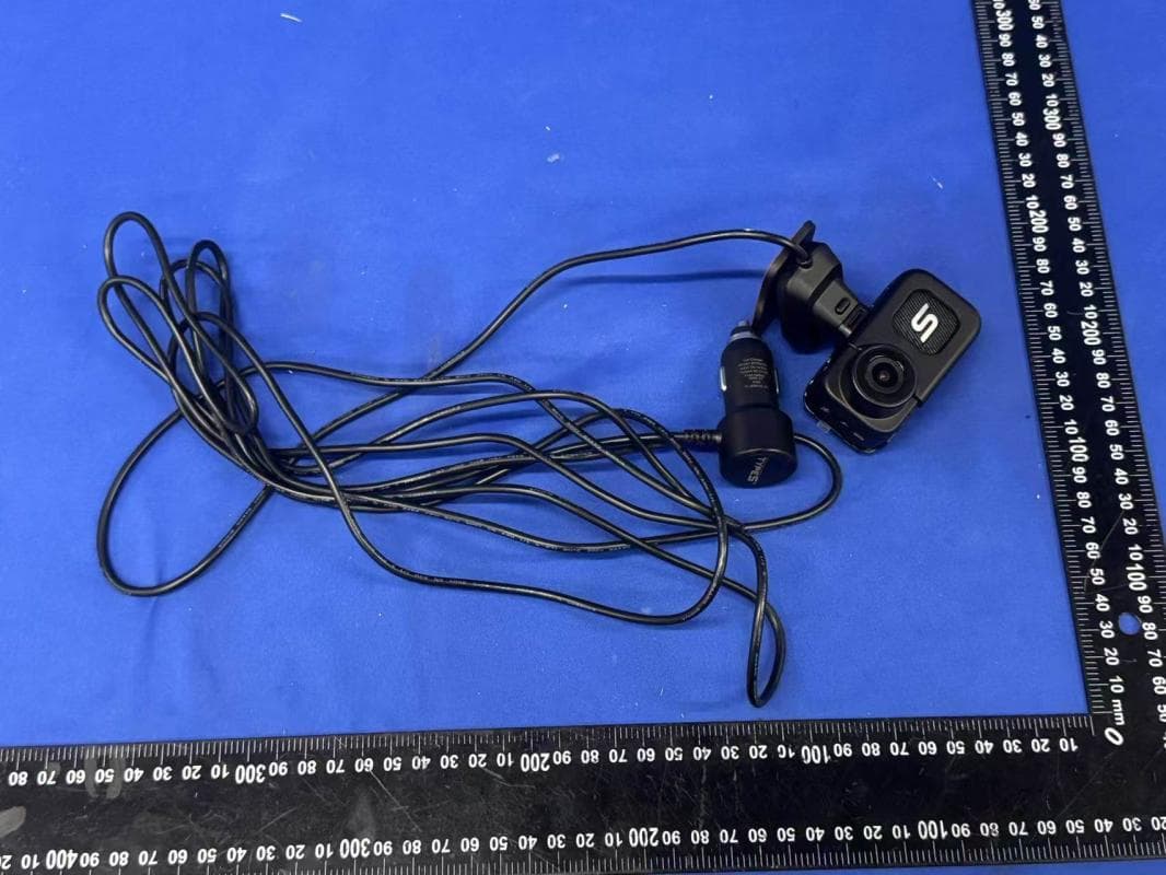
WUI-4KMINI
Sep 21, 20254K Dash Cam & Body cam
Equipment Class
NII - Unlicensed National Information Infrastructure TX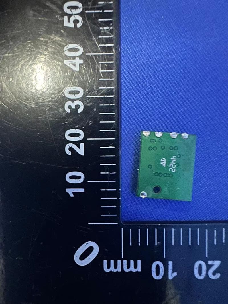
WUI-TTGEN2
Mar 24, 2024MODULE OF TTGEN2
Equipment Class
DTS - Digital Transmission System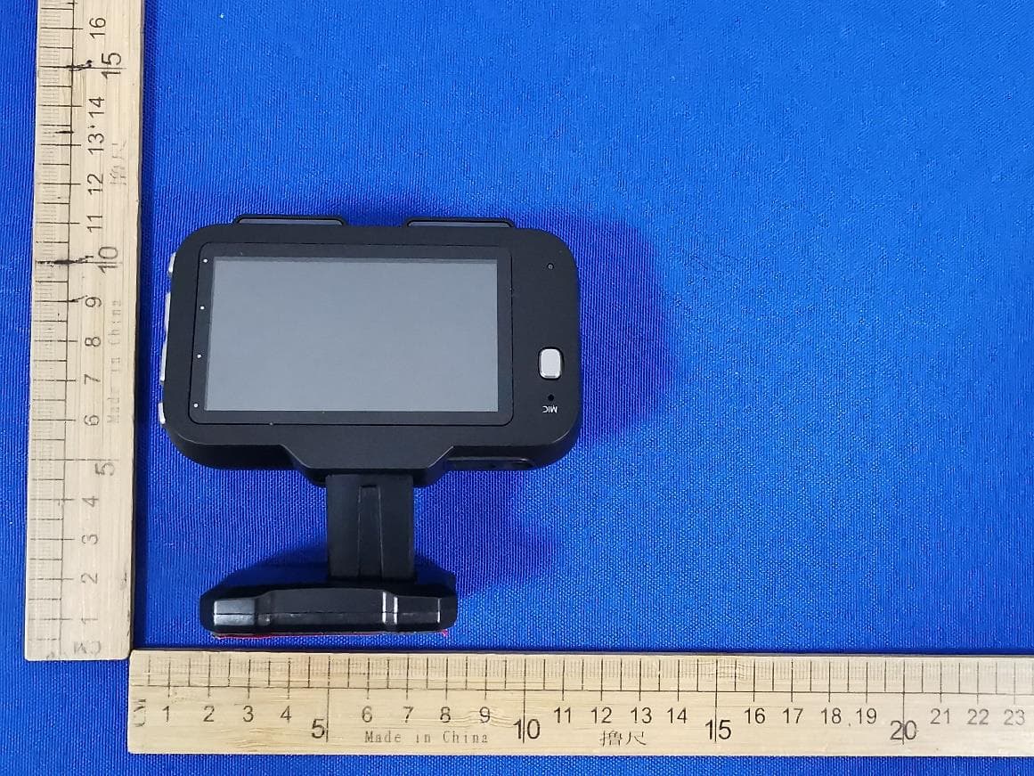
WUI-YDAICAMWIFI
Nov 07, 2023Roadcam AI Plus
Equipment Class
DTS - Digital Transmission System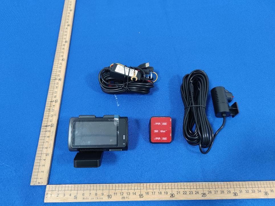
WUI-AICAMWIFI
Oct 31, 2023T200 PLUS 2K AI Dash Cam + 1080P Rear Cam
Equipment Class
DTS - Digital Transmission System