WUIYX-BM0XBluetooth module
Winplus Co., Ltd.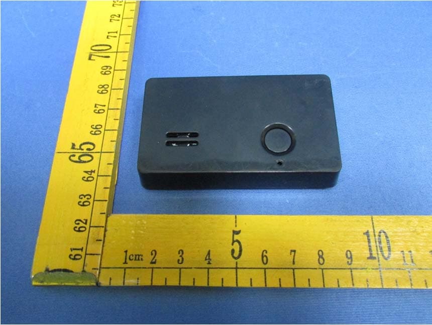
Click to zoom
Application Details
- Equipment Class
- DTS - Digital Transmission System
- Date of Grant
- Sep 22, 2015
- Application Purpose
- Original Equipment
- Date of Application
- Sep 22, 2015
- Equipment Note
- Bluetooth module
- Frequency Range
- 2402.00000000 - 2480.00000000
- Company
- Winplus Co., Ltd.
- Country
- Hong Kong
Documents & Files
Document Text
Text extracted from the exhibit documents filed with the FCC. Open a document above to read the original.
Users Manual
Winplus Co., Ltd. YX-BM0X 1 OEM/integrators installation Manual YX‐BM0X 蓝牙4.0模块说明书 Name: Bluetooth 4.0 Module 名称:蓝牙4.0模块 Model No.: YX-BM0X 型号:YX-BM0X Revision: V1.0 版本:V1.0 Version Remark Approve Date V1.0 First release Li Mingxing 01-12-2014 Winplus Co., Ltd. YX-BM0X 2 CONTENTS 1 Overview ................................................................................................................................................. 3 2 Applications ............................................................................................................................................ 3 3 Electrical Specification ........................................................................................................................... 4 4 Pin Definition .......................................................................................................................................... 4 5 Physical Dimensions ............................................................................................................................... 5 6 Reference Circuit ..................................................................................................................................... 6 7 Product Model ......................................................................................................................................... 7 7.1 Model naming rule ...................................................................................................................... 7 7.2 Ordering product model .............................................................................................................. 7 8 Declaration .............................................................................................................................................. 7 9 Host Information ..................................................................................................................................... 7 10 Installation ....................................................................................................................................... 7 11 Antenna Characteristics ........................................................................................................................... 8 12 FCC Information ............................................................................................................................. 8 Winplus Co., Ltd. YX-BM0X 3 1 Overview YX-BM0X is a kind of SMD/PIN type Bluetooth 4.0 module,using nRF51822 micro controller of Nordic company.This module has higher performance-price retio,lower-power consumption system on chip(Soc),especially suitable for BLE application.It lowers the cost to build up net nodes, Its shardware resources include a ARM Core(cortex-m0),high sensitivity 2.4GHz transceiver,128K/256K embedded FLASH memory,16KB/32KB RAM,and other powerful subsidinary resources,can be flexibly used in ultra-low power consumption,ultra-low sleep circuit system. Key Features: - Support Bluetooth low energy mode - Remarkable Link budge(up to -93 dBm) - Accurate transceiver signal strength test(RSSI) - Meeting standard of CE (EUR) and FCC(US) - High-performance ARM Cortex M0 controller - Inner Temperature sensor and low power comparator - AES HW encryption - Operation Temperature: -20°C to +60°C Module picture: 2 Applications - Low-power consumption systems Winplus Co., Ltd. YX-BM0X 4 - Cellular phone accessories - Sports and fitness equipments - Consumer electronics - Human inter face devices - Health and Medical devices - Bluetooth LED lights,sockets 3 Electrical Specification NAME RANGE REMARK RF frequency 2400MHz-2483MHz Power supply 1.8-3.6V Max transmit Power +4dBm Data Rate 250K/1M/2Mbps transmit current 10mA@0dBm output receive current 13mA@2Mbps MCU working current 4.4mA@16MHz@3V Start from Flash MCU working current 2.4mA@16MHz@3V Start from RAM MCU IDlE mode 2.3uA@3V ON mode,all block idle MCU OFF mode 420uA@3V OFF mode Typcal sensitivity -96dBm@250kbps 0.1%BER 4 Pin Definition NO. NAME TYPEREMARK 1 VDD POWER PINDC1.8‐3.6V working voltage 2 P0.00 GPIO GPIO, PWM output(RED) 3 P0.01 GPIO GPIO, PWM output(GREEN) 4 P0.09 GPIO GPIO, PWM output(BLUE) 5 P0.11 GPIO GPIO, PWM output(WHITE) 6 SWDIO SIGNAL 7 SCLK SIGNAL Winplus Co., Ltd. YX-BM0X 5 8 GND POWER GROUND 5 Physical Dimensions PCB onboard antenna (uint:mil), PCB thickness:1.0mm;PCB+MCU thickness:1.9mm。 Winplus Co., Ltd. YX-BM0X 6 6 Reference Circuit Remark: 1. The power of the LED Drive Module in above figure, should be chose according to actual customer requirement of the product’s power.Recommended use is the Constant current module with output range from 16V~20V 2. The LED count of series and paralle connections is decided by customer’s designed power of the product.The values and power of R1,R3,R5,R7 are calculated according to the product’s LED parameters. 3. To R2、R4、R6、R8 ,the recommended resitance value and package are 100ohm and 0603. Winplus Co., Ltd. YX-BM0X 7 7 Product Model 7.1 Model naming rule YX BMxx Macrothings Company Bluetooth Module 0‐9,A‐Z, Hardware version 0‐9,A‐Z, Software version 7.2 Ordering product model Product model Remark YX‐BM0X bluetooth(4.0BLE) true color LED module() 8 Declaration The content of this product specification is for reference only. If there are some modifications, please forgive no further notice. Shenzhen Macrothings Co.,LTD has the final explanation right of the product’s specification. 9 Host Information Host Brand name: Winplus Host model number: LM55369 Host manufacturer: Winplus Company Ltd 10 Installation This product is mounted inside of the end product by professional installers OEM. They use this module with changing the power and control signal setting by software of end product within the scope of this application. End user can not change this setting. Winplus Co., Ltd. YX-BM0X 8 11 Antenna Characteristics That separate approval is required for all other operating configurations, includi…
Text truncated - open the document above for the full version.
Cover Letter(s)
Winplus Co., Ltd. Modular Approval Declaration Letter (Date) 08/28/2015 (Product name) FCC ID : WUIYX-BM0X , is seeking FCC Authorization as a Single Modular transmitter / Single Limited Modular Approval (Please check one). The EUT meets the requirements for Single Modular approval / Single Limited Modular Approval (please check one) as detailed in FCC public Notice DA00-1407. Compliance to each of the requirements is described below : Host Information: Host Brand name: Winplus Host model number: LM55369 Host manufacturer: Winplus Company Ltd Questions are: * Please provide a detailed explanation if the answer is “No.” Item Modular requirement Yes No 1 The radio elements must have the radio frequency circuitry shielded. Physical components and tuning capacitor(s) may be located external to the shield, but must be on the module assembly; Re: Device is not equipped with metal shielding to cover RF section.This module uses SMD type components which can not be modified by user. 2 The module must have buffered modulation/data inputs to ensure that the device will comply with Part 15 requirements with any type of input signal; 3 The module must contain power supply regulation on the module; Re: Internal 3.3V power regulator. Refer to circuit diagram. 4 The module must contain a permanently attached antenna, or contain a unique antenna connector, and be marketed and operated only with specific antenna(s), per Sections 15.203, 15.204(b), 15.204(c), 15.212(a), 2.929(b); 5 The module must demonstrate compliance in a stand-alone configuration; 6 The module must be labelled with its permanently affixed FCC ID label, or use an electronic display (See KDB Publication 784748 about labelling requirements); 7 The module must comply with all specific rules applicable to the transmitter including all the conditions provided in the integration instructions by the grantee; 8 The module must comply with RF exposure requirements Note: (1) LMA may be granted when one or more of the requirements in the table above cannot be demonstrated. LMA will also be issued in those instances where applicants can demonstrate that they will retain control over the final installation of the device, such that compliance of the end product is assured. In such cases, an operating condition on the LMA for the module must state that the module is only approved for use when installed in devices produced by a specific manufacturer. When LMA is sought, the application for equipment certification must specifically state how control of the end product into which the module will be installed, and will be maintained, such that full compliance of the end product is always ensured. (2) Please provide Clear and specific instructions describing the conditions, limitations and procedures for third-parties to use and/or integrate the module into a host device. (3) For non-Software Defined Radio transmitter modules where software is used to ensure compliance of the device, technical description of how such control is implemented to ensure prevention of third party modification must be provided (see KDB 594280). Note 1: Compliance of a module in its final configuration is the responsibility of the applicant. A host device will not be considered certified if the instructions regarding antenna configuration provided in the original description, of one or more separately certified modules it contains, were not followed. Example: A separately certified low-power transceiver module using Bluetooth technology which is housed in a desktop computer, laptop or peripheral does not require the overall system to be recertified, if the desktop computer, laptop or peripheral, as a stand-alone unit, complies with all applicable technical standards. Client’s signature Benson Leung / Director Client’s name / title Winplus Co., Ltd.
Cover Letter(s)
Winplus Co., Ltd. LMA Declaration Letter We, (Winplus Co., Ltd.), declare that we will retain control over the final installation of the device, (FCC ID: WUIYX-BM0X) so that compliance of the end product is assured. In such cases, an operating condition on the LMA for the module must be only approved for use when installed in devices produced by a specific manufacturer. Client’s signature Benson Leung / Director Client’s name / title Winplus Co., Ltd.
Cover Letter(s)
Winplus Co., Ltd. Date:2015-09-10 FCC ID: WUIYX-BM0X Re: Limited single-modular transmitter To Whom It May Concern This is a complete RF module with an integral reference oscillator. External connections are provided for power and data communication. Its shardware resources include a ARM Core(cortex-m0),high sensitivity 2.4GHz transceiver,128K/256K embedded FLASH memory,16KB/32KB RAM, and other powerful subsidinary resources, can be flexibly used in ultra-low power consumption, ultra-low sleep circuit system. Control command will be wrote into RAM. Pin VDD is power supply port. Pins P0.00,P0.01,P0.09 and P0.11 is PWM output ports. Its send control signals to external circuit system. Pins SWDIO and SCLK is signal ports. Pin GND is ground. Application example Remark: 1. The power of the LED Drive Module in above figure, should be chose according to actual customer requirement of the product’s power.Recommended use is the Constant current module with output range from 16V~20V. 2. The LED count of series and paralle connections is decided by customer’s designed power of the product.The values and power of R1,R3,R5,R7 are calculated according to the product’s LED parameters. 3. To R2、R4、R6、R8 ,the recommended resitance value and package are 100ohm and 0603. Host Brand name: Winplus Host model number: LM55369 Host manufacturer: Winplus Company Ltd Signature: Benson Leung / Director Client’s name / title Winplus Co., Ltd.
External Photos
Host External Photos
ID Label/Location Info
FCC Label Sample for model: YX-BM0X The device is so small or for such use that it is not practicable to place the statement specified under paragraph (a) of FCC Part15.19 section on it, the information required by this paragraph shall be placed in a prominent location in the instruction manual. However, the FCC identifier or the unique identifier, as appropriate, must be displayed on the device. YX-BM0X FCC ID:WUIY X-BM0X
ID Label/Location Info
FCC Label Sample for model: YX-BM0X The device is so small or for such use that it is not practicable to place the statement specified under paragraph (a) of FCC Part15.19 section on it, the information required by this paragraph shall be placed in a prominent location in the instruction manual. However, the FCC identifier or the unique identifier, as appropriate, must be displayed on the device. YX-BM0X FCC ID:WUIY X-BM0X
Internal Photos
Host Internal photos Bluetooth module
Test Report
TEST REPORT Waltek Services (Shenzhen) Co.,Ltd. http://www.waltek.com.cn Reference No. .................... : WTS15S0627846E FCC ID ................................ : WUIYX-BM0X Applicant ............................ : Winplus Co., Ltd. Address .............................. : Suites 6-11, 7th Floor, Corporation Park, 11 On La Shatin Hong Kong Manufacturer .................... : Shenzhen Macrothings Technology Co., Ltd. Address .............................. : Room 1812, Sangtai Building, Lishan Road, Nanshan District, Shenzhen City, Guangdong Province, China Product Name .................... : Bluetooth module Model No. ........................... : YX-BM0X Standards........................... : FCC CFR47 Part 15 Section 15.247:2014 Date of Receipt sample .... : Jun. 06, 2015 Date of Test ....................... : Jun. 07, 2015 - Jun.12, 2015 Date of Issue ...................... : Jun,15, 2015 Test Result ......................... : Pass Remarks: The results shown in this test report refer only to the sample(s) tested, this test report cannot be reproduced, except in full, without prior written permission of the company. The report would be invalid without specific stamp of test institute and the signatures of compiler and approver. Prepared By: Waltek Services (Shenzhen) Co., Ltd. Address: 1/F., Fukangtai Building, West Baima Road, Songgang Street, Baoan District, Shenzhen, Guangdong, China Tel :+86-755-83551033 Fax:+86-755-83552400 Tested by: Approved by: Tiger Ye / Engineer Philo Zhong / Manager Reference No.: WTS15S0627846E Page 2 of 30 Waltek Services (Shenzhen) Co.,Ltd. http://www.waltek.com.cn 2 Test Summary Test Items Test Requirement Result Radiated Emissions 15.205(a) 15.209(a) PASS Conducted Emissions 15.207(a) N/A 6dB Bandwidth 15.247(a)(2) PASS Maximum Peak Output Power 15.247(b)(3),(4) PASS Power Spectral Density 15.247(e) PASS Band Edge 15.247(d) PASS Antenna Requirement 15.203 PASS Maximum Permissible Exposure (Exposure of Humans to RF Fields) 1.1307(b)(1) PASS Reference No.: WTS15S0627846E Page 3 of 30 Waltek Services (Shenzhen) Co.,Ltd. http://www.waltek.com.cn 3 Contents Page 1 COVER PAGE ........................................................................................................................................... 1 2 TEST SUMMARY .................................................................................................................................................. 2 3 CONTENTS ............................................................................................................................................................ 3 4 GENERAL INFORMATION .................................................................................................................................. 4 4.1 GENERAL DESCRIPTION OF E.U.T. ................................................................................................................ 4 4.2 DETAILS OF E.U.T. ......................................................................................................................................... 4 4.3 CHANNEL LIST ................................................................................................................................................. 4 4.4 TEST MODE ..................................................................................................................................................... 4 4.5 TEST FACILITY ................................................................................................................................................. 5 5 EQUIPMENT USED DURING TEST .................................................................................................................. 6 5.1 EQUIPMENTS LIST ........................................................................................................................................... 6 5.2 DESCRIPTION OF SUPPORT UNITS ................................................................................................................. 6 5.3 MEASUREMENT UNCERTAINTY ....................................................................................................................... 7 5.4 TEST EQUIPMENT CALIBRATION ..................................................................................................................... 7 6 CONDUCTED EMISSIONS .................................................................................................................................. 8 7 RADIATED EMISSIONS....................................................................................................................................... 9 7.1 EUT OPERATION ............................................................................................................................................. 9 7.2 TEST SETUP .................................................................................................................................................. 10 7.3 SPECTRUM ANALYZER SETUP ...................................................................................................................... 11 7.4 TEST PROCEDURE ........................................................................................................................................ 12 7.5 SUMMARY OF TEST RESULTS ....................................................................................................................... 13 8 BAND EDGE MEASUREMENT ........................................................................................................................ 16 8.1 TEST PRODUCE ............................................................................................................................................. 16 8.2 TEST RESULT ................................................................................................................................................ 17 9 6 DB BANDWIDTH MEASUREMENT ......................................................…
Text truncated - open the document above for the full version.
Test Setup Photos
Page 1 of 3 Waltek Services (Shenzhen) Co.,Ltd. http://www.waltek.com.cn Photographs – Model YX-BM0X Test S etup Radiated Emission Test frequency below 30MHz Test frequency 30MHz - 1GHz Page 2 of 3 Waltek Services (Shenzhen) Co.,Ltd. http://www.waltek.com.cn Test frequency above 1GHz Page 3 of 3 Waltek Services (Shenzhen) Co.,Ltd. http://www.waltek.com.cn
Contact Information
Applicant
Benson H Leung(Director)
Test Firm
Waltek Services(Shenzhen) Co., Ltd.philo zhong
Technical Specifications
| # | Rule Parts | Frequency Range | Power Output |
|---|---|---|---|
| 1 | 15C | 2.40 GHz - 2.48 GHz | 2.00 mW |
Other Applications from Winplus Co., Ltd.

WUI-RV433RC
Jan 04, 2026Remote control
Equipment Class
DSC - Part 15 Security/Remote Control Transmitter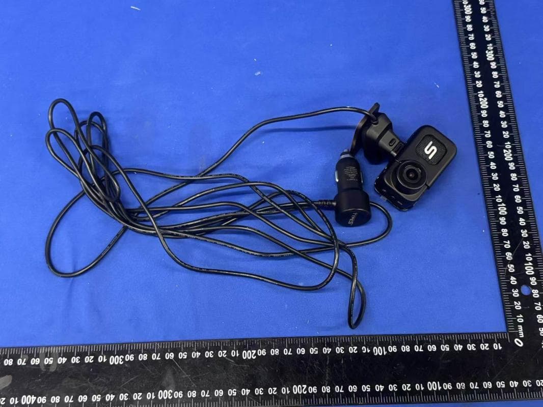
WUI-4KMINI
Sep 21, 20254K Dash Cam & Body cam
Equipment Class
NII - Unlicensed National Information Infrastructure TX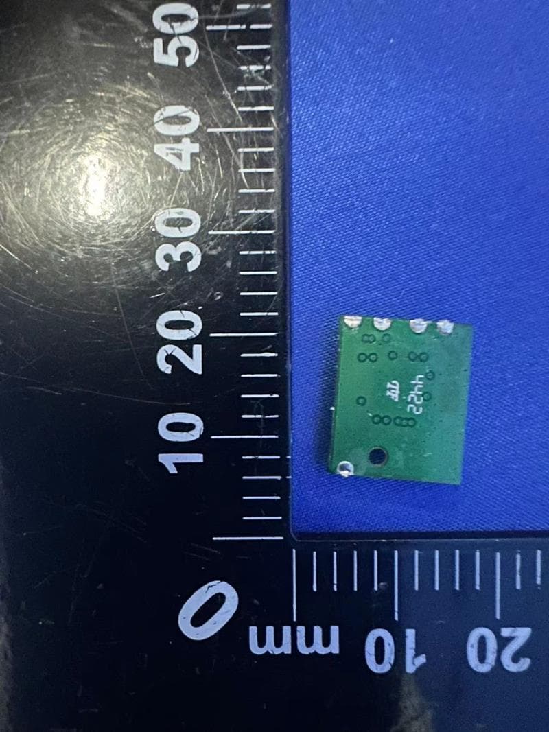
WUI-TTGEN2
Mar 24, 2024MODULE OF TTGEN2
Equipment Class
DTS - Digital Transmission System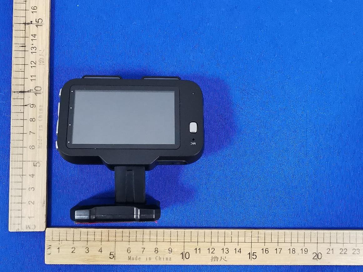
WUI-YDAICAMWIFI
Nov 07, 2023Roadcam AI Plus
Equipment Class
DTS - Digital Transmission System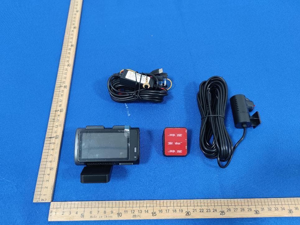
WUI-AICAMWIFI
Oct 31, 2023T200 PLUS 2K AI Dash Cam + 1080P Rear Cam
Equipment Class
DTS - Digital Transmission System