WXF-MX1101Relative Humidity Data Logger
Onset Computer Corporation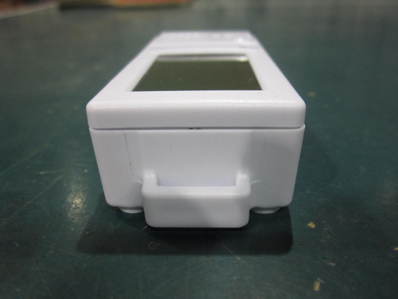
Click to zoom
Application Details
- Equipment Class
- DTS - Digital Transmission System
- Date of Grant
- Jul 22, 2014
- Application Purpose
- Original Equipment
- Date of Application
- Jul 22, 2014
- Equipment Note
- Relative Humidity Data Logger
- Frequency Range
- 2400.00000000 - 2483.50000000
- Company
- Onset Computer Corporation
- Country
- United States
Documents & Files
Document Text
Text extracted from the exhibit documents filed with the FCC. Open a document above to read the original.
Users Manual
Quick Start for the HOBO® MX Temp/RH Logger (MX1101) 1 Go to the App Store et download HOBOmobile™ to your iPhone®, iPod touch®, or iPad®. 2 Install the batteries in the logger. Open the battery door on the back of the logger and insert two AAA batteries observing polarity. Reinsert the battery door and snap it back into place. 3 Open HOBOmobile. Enable Bluetooth® in your device settings if prompted. 4 In HOBOmobile, tap . The logger should appear in the Recently Seen/In Range list shown in step 5. If the logger does not appear, make sure the logger is within range of your device. 5 Tap a row in the Recently Seen/In Range list to connect to the logger. 6 Once connected, tap Configure to set up and start the logger. 7 Choose your logger settings and then tap Start in the upper right corner of the Configure screen. The logger will begin logging data based on the settings you selected. 8 Deploy the logger using the magnets on the back of the logger case or the mounting materials included. 9 To offload data from the logger to your device, connect to it and tap Readout (shown in example in step 6). The data from the logger is saved to your device. Tap and then tap the mini‐ graph to view a larger version of the graph or to share the file. For help with HOBOmobile or more information about this logger, tap the About icon in the app, scan the code at right or go to: www.onsetcomp.com/HOBOmobile 17839‐A MAN‐QSG‐MX1101 Quick Start for the HOBO® MX Temp/RH Logger (MX1101) 1 Go to the App Store and download HOBOmobile™ to your iPhone®, iPod touch®, or iPad®. 2 Install the batteries in the logger. Open the battery door on the back of the logger and insert two AAA batteries observing polarity. Reinsert the battery door and snap it back into place. 3 Open HOBOmobile. Enable Bluetooth® in your device settings if prompted. 4 In HOBOmobile, tap . The logger should appear in the Recently Seen/In Range list shown in step 5. If the logger does not appear, make sure the logger is within range of your device. 5 Tap a row in the Recently Seen/In Range list to connect to the logger. 6 Once connected, tap Configure to set up and start the logger. 7 Choose your logger settings and then tap Start in the upper right corner of the Configure screen. The logger will begin logging data based on the settings you selected. 8 Deploy the logger using the magnets on the back of the logger case or the mounting materials included. 9 To offload data from the logger to your device, connect to it and tap Readout (shown in example in step 6). The data from the logger is saved to your device. Tap and then tap the mini‐ graph to view a larger version of the graph or to share the file. For help with HOBOmobile or more information about this logger, tap the About icon in the app, scan the code at right or go to: www.onsetcomp.com/HOBOmobile 17839‐A MAN‐QSG‐MX1101 Federal Communication Commission Interference Statement This equipment has been tested and found to comply with the limits for a Class B digital device, pursuant to Part 15 of the FCC Rules. These limits are designed to provide reasonable protection against harmful interference in a residential installation. This equipment generates uses and can radiate radio frequency energy and, if not installed and used in accordance with the instructions, may cause harmful interference to radio communications. However, there is no guarantee that interference will not occur in a particular installation. If this equipment does cause harmful interference to radio or television reception, which can be determined by turning the equipment off and on, the user is encouraged to try to correct the interference by one of the following measures: Reorient or relocate the receiving antenna Increase the separation between the equipment and receiver Connect the equipment into an outlet on a circuit different from that to which the receiver is connected Consult the dealer or an experienced radio/TV technician for help This device complies with Part 15 of the FCC Rules. Operation is subject to the following two conditions: (1) This device may not cause harmful interference, and (2) this device must accept any interference received, including interference that may cause undesired operation. FCC Caution: Any changes or modifications not expressly approved by the party responsible for compliance could void the user's authority to operate this equipment. Industry Canada Statement This device complies with Industry Canada license‐exempt RSS standard(s). Operation is subject to the following two conditions: (1) this device may not cause interference, and (2) this device must accept any interference, including interference that may cause undesired operation of the device. Avis de conformité pour l’Industrie Canada Le présent appareil est conforme aux CNR d'Industrie Canada applicables aux appareils radio exempts de licence. L'exploitation est autorisée aux deux conditions suivantes : (1) l'appareil ne doit pas produire de brouillage, et (2) l'appareil doit accepter tout brouillage radioélectrique subi, même si le brouillage est susceptible d'en compromettre le fonctionnement. To comply with FCC and Industry Canada RF radiation exposure limits for general population, the HOBO MX1101 loggers must be installed to provide a separation distance of at least 20cm from all persons and must not be co‐located or operating in conjunction with any other antenna or transmitter. 1‐800‐LOGGERS (564‐4377) • 508‐759‐9500 www.onsetcomp.com • [email protected] © 2014 Onset Computer Corporation. All rights reserved. Onset, HOBO, and HOBOmobile are trademarks or registered trademarks of Onset Computer Corporation. iPhone, iPad, and iPod touch are registered trademarks of Apple Inc. Bluetooth is a registered trademark of Bluetooth SIG, Inc. All other trademarks are the property of their respective companies. 17839‐A MAN‐QSG‐MX1101 Federal Communication Commission Interference Statement This equipment has been tested a…
Text truncated - open the document above for the full version.
Cover Letter(s)
Onset Computer Corporation 470 MacArthur Blvd. Bourne, MA 02532 USA Tel: 508-759-9500 Fax: 508-759-9100 Web: www.onsetcomp.com Email: sales @onsetcomp.com 6/27/2014 To: Federal Communications Commission 7435 Oakland Mills Road Columbia, MD 21046-1609 Curtis-Straus LLC TCB 1 Distribution Center Circle, #1 Littleton, MA 01460 Re: Confidentiality Request Gentlemen: This letter is to comply with 47 CFR 0.457(d)(2) pertaining to confidential material. Onset Computer Corporation requests that the following documents regarding this submission for FCC ID WXF-MX1101 be kept confidential: 1. Schematics 2. Block Diagram 3. Circuit/Technical Description The material above contains technical data, which would customarily be guarded from competitors. Sincerely, Jacob Lacourse Electrical Engineer 6/27/2014 onset ®
Cover Letter(s)
Onset Computer Corporation 470 MacArthur Blvd. Bourne, MA 02532 USA Tel: 508-759-9500 Fax: 508-759-9100 Web: www.onsetcomp.com Email: sales @onsetcomp.com Agent’s Authorization Letter 6/27/2014 I, an officer of Onset Computer Corporation, do hereby authorize, until further notice, Christopher Reynolds of Curtis-Straus LLC, 1 Distribution Center Circle, #1, Littleton, MA 01460, to act on our behalf in dealings before the Federal Communications Commission with respect to all matters relating to equipment authorizations under 47 CFR. This authorization includes, but is not limited to, the signing of Form 731. I certify that no party (as defined in 47 CFR 1.2002) to this application, including myself, is subject to a denial of federal benefits, that include FCC benefits, pursuant to section 5301 of the Anti-Drug Abuse Act of 1988, 21 U.S.C., 853A. Certified By: Jacob Lacourse Electrical Engineer 6/27/2014 onset ®
RF Exposure Info
Prediction of MPE limit at a given distance Equation from page 18 of OET Bulletin 65, Edition 97-01 where:S = power density P = power input to the antenna G = power gain of the antenna in the direction of interest relative to an isotropic radiator R = distance to the center of radiation of the antenna Maximum peak output power at the antenna terminal:0.55(dBm) Maximum peak output power at the antenna terminal:1.135010816(mW)P Antenna gain(typical):-2(dBi) Maximum antenna gain:0.630957344(numeric)G Prediction distance:20(cm)R Prediction frequency:2402(MHz) MPE limit for uncontrolled exposure at prediction frequency:1(mW/cm^2) Power density at prediction frequency:0.000142(mW/cm^2) Maximum allowable antenna gain:36.46269855(dBi) 2 4 R PG S p =
Test Report
Curtis-Straus LLC is accredited by the American Association for Laboratory Accreditation for the specific scope of accreditation under Certificate Number 1627-01. This report may contain data which is not covered by the A2LA accreditation. ____________________________________________________________ Curtis-Straus LLC, a wholly owned subsidiary of BV CPS One Distribution Center Circle, #1 Littleton, MA TEL (978) 486-8880 FAX (978) 486-8828 page 1 of 29 Test Report Curtis-Straus LLC, a wholly owned subsidiary of BV CPS Report No EO0877-1 Client Onset Computer Corporation Jacob Lacourse Address 470 MacArthur Blvd. Bourne, MA 02532 Phone 508-743-3195 Items tested MX1101 FCC ID IC WXF-MX1101 7936A-MX1101 FRN 0009380064 Equipment Type Part 15.247 Digitally Modulated Equipment Code DTS FCC/IC Rule Parts 47 CFR 15.247, RSS-210 Issue 8, RSS GEN Issue 3 Test Dates June 3 – 11, 2014 Results As detailed within this report Prepared by Tuyen Truong A. – Test Engineer Authorized by Christopher Reynolds – EMC Supervisor Issue Date 7/3/2014 Conditions of Issue This Test Report is issued subject to the conditions stated in the ‘Conditions of Testing’ section on page Error! Bookmark not defined. of this report. Test Report for Onset Computer Corporation. Report No. EO0877-1 July 1, 2014 ______________________________________________________________________ ____________________________________________________________ Curtis-Straus LLC, a wholly owned subsidiary of BV CPS One Distribution Center Circle, #1 Littleton, MA TEL (978) 486-8880 FAX (978) 486-8828 page 2 of 29 Contents Contents .................................................................................................................................. 2 Summary ................................................................................................................................. 3 Test Methodology .................................................................................................................... 4 Product Tested - Configuration Documentation ....................................................................... 5 Statement of Conformity ...................................................................................................... 6 Test Results ............................................................................................................................ 7 Bandwidth ............................................................................................................................ 7 Fundamental Emission Output Power ................................................................................ 10 Radiated Spurious Emissions ............................................................................................ 13 Conducted Spurious Emissions ......................................................................................... 16 Power Spectral Density ...................................................................................................... 19 AC Line Conducted Emissions ........................................................................................... 22 Occupied Bandwidth .......................................................................................................... 23 Duty Cycle Correction Calculation ...................................................................................... 26 Measurement Uncertainty...................................................................................................... 27 Conditions Of Testing ............................................................................................................ 28 Form Final Report REV 7-20-07 (DW) Test Report for Onset Computer Corporation. Report No. EO0877-1 July 1, 2014 ______________________________________________________________________ _____________________________________________________________ Curtis-Straus LLC, a wholly owned subsidiary of BV CPS One Distribution Center Circle, #1 Littleton, MA TEL (978) 486-8880 FAX (978) 486-8828 page 3 of 29 Summary This test report supports an application for certification of a transmitter operating pursuant to 47 CFR 15.247. The product is the MX1101. It is a digitally modulated transmitter that operates in the range 2400-2483.5MHz. Product was tested with an on board antenna with a gain of -2dBi. We found that the products met the above requirements without modification. Jacob Lacourse from Onset Computer Corporation was present during the testing. The test samples were received in good condition. Test Report for Onset Computer Corporation. Report No. EO0877-1 July 1, 2014 ______________________________________________________________________ _____________________________________________________________ Curtis-Straus LLC, a wholly owned subsidiary of BV CPS One Distribution Center Circle, #1 Littleton, MA TEL (978) 486-8880 FAX (978) 486-8828 page 4 of 29 Test Methodology Radiated emission and AC Line conducted testing were performed according to the procedures specified in FCC Guidance for performing compliance measurement on DTS operating under section 15.247, April 19, 2013 and ANSI C63.10 (2009) and C63.4 (2003). Radiated Emissions were maximized by rotating the device around its axes as well as varying the test antenna’s height and polarity. The antenna was maximized separately. Conducted emissions at the antenna port were performed, as required by rule section. The EUT operating voltage is 3Vdc (2xAAA battery). No AC Line conducted testing required. Low operating channel frequency = 2402MHz Mid operating channel frequency = 2440MHz High operating channel frequency = 2480MHz The following bandwidths were used during radiated spurious and line conducted emissions. Frequency RBW VBW 0.15-30MHz 9kHz 30kHz 30-1000MHz 120kHz 1MHz 1-10GHz 1MHz 3MHz Test Report for Onset Computer Corporation. Report No. EO0877-1 July 1, 2014 ______________________________________________________…
Text truncated - open the document above for the full version.
Test Setup Photos
Conducted Antenna port tests Radiated Emission
Contact Information
Applicant
James Corrigan
Test Firm
BUREAU VERITAS CONSUMER PRODUCTS SERVICES, INC.Ozgur Ozturk
[email protected]978-486-8880
Technical Specifications
| # | Rule Parts | Frequency Range | Power Output |
|---|---|---|---|
| 1 | 15C | 2.40 GHz - 2.48 GHz | 716.00 µW |
Other Applications from Onset Computer Corporation
WXF-ONST17
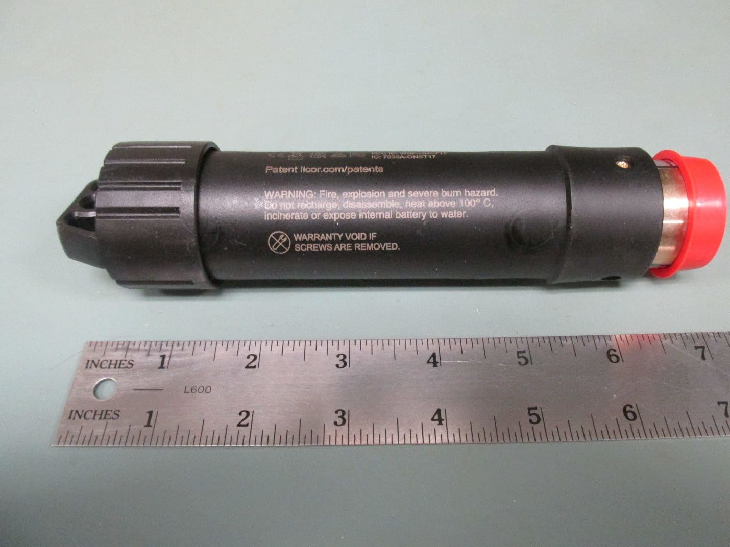
Jun 29, 2026HOBO MX Underwater PAR Data Logger
Equipment Class
DTS - Digital Transmission System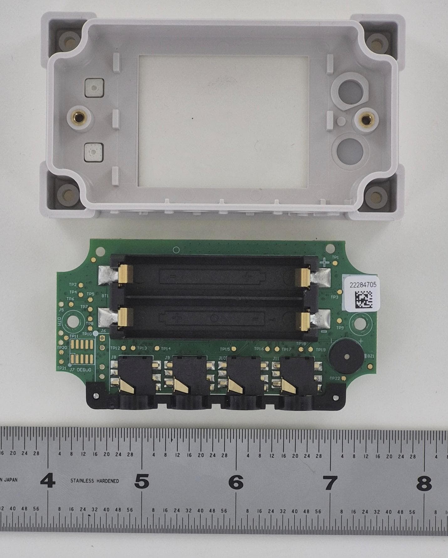
WXF-ONST8
Dec 17, 2025HOBO MX Analog/Temp/RH/Light Data Logger, InTemp CX460 4-Channel Analog Data logger
Equipment Class
DTS - Digital Transmission System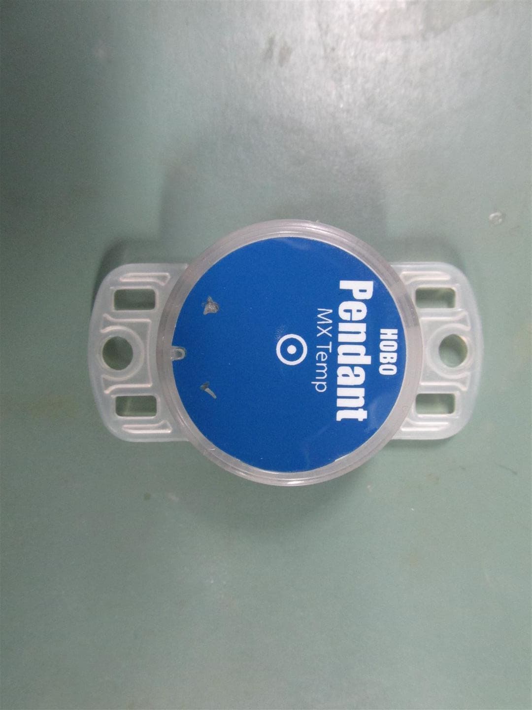
WXF-ONST4
Aug 16, 2020HOBO Pendant MX Loggers
Equipment Class
DTS - Digital Transmission System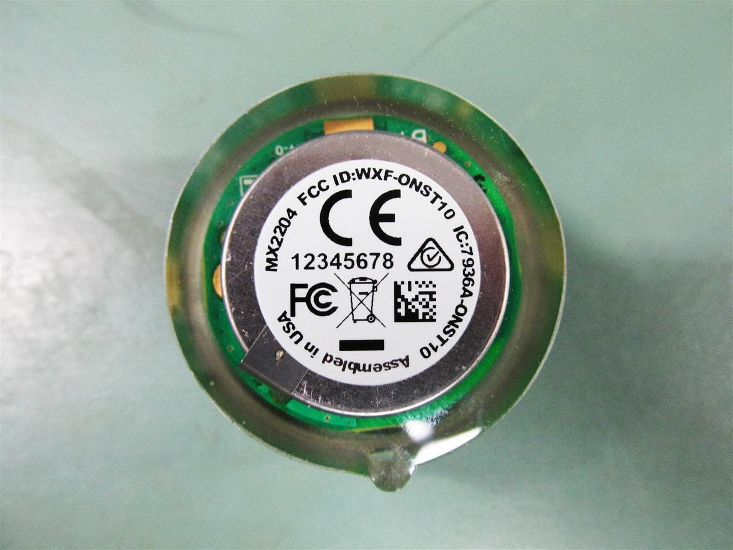
WXF-ONST10
Aug 16, 2020HOBO TidbiT MX Loggers
Equipment Class
DTS - Digital Transmission System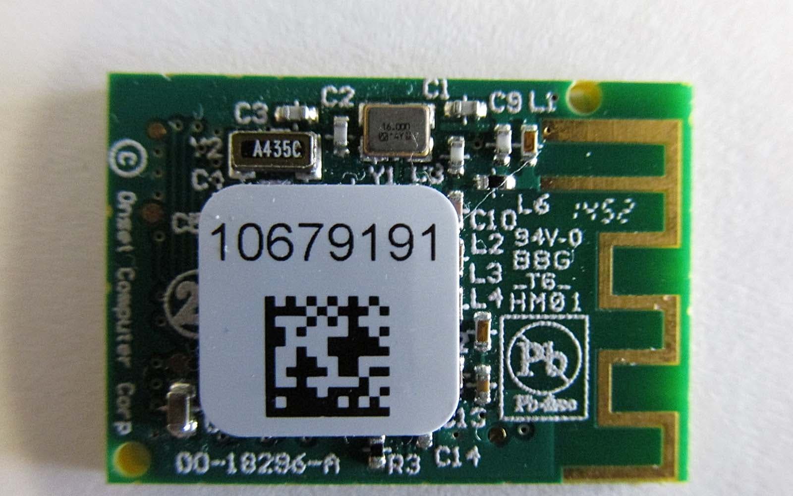
WXF-ONST1
Jun 03, 2015Digital Transmission
Equipment Class
DTS - Digital Transmission System