WXF-ONST17HOBO MX Underwater PAR Data Logger
Onset Computer Corporation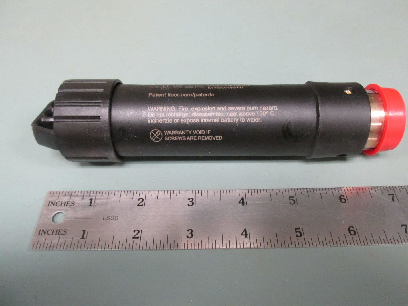
Click to zoom
Application Details
- Equipment Class
- DTS - Digital Transmission System
- Date of Grant
- Jun 29, 2026
- Application Purpose
- Original Equipment
- Equipment Note
- HOBO MX Underwater PAR Data Logger
- Frequency Range
- 2402.00000000 - 2480.00000000
- Company
- Onset Computer Corporation
- Country
- United States
Documents & Files
Document Text
Text extracted from the exhibit documents filed with the FCC. Open a document above to read the original.
Users Manual
HOBO® MX Underwater PAR Data Logger (MX2502) Manual 29772-A The HOBO MX2502 PAR/Temp/Tilt Data Logger measures underwater photosynthetically active radiation (PAR), temperature, and tilt in a single device. This Bluetooth®- enabled logger is designed for wireless communication with a phone, tablet, or computer. Using the HOBOconnect® app, you can easily configure the logger then download logged data to view or export for further analysis. The logger can calculate minimum, maximum, average, and standard deviation statistics and be configured to indicate alarms at thresholds you specify. The logger also supports burst logging, in which data is logged at a faster interval when sensor readings are above or below certain limits. It offers a wide range of solutions for monitoring PAR, temperature, and tilt in numerous applications. Specifications Temperature Sensor Range -20° to 50°C (-4° to 122°F) Accuracy ±0.2°C Resolution 0.008°C (0.014°F) Drift <0.01°C (0.018°F) per year Response Time (90%) 12 minutes in water (typical) Tilt Angle Range 0 to 180° from vertical Accuracy ±5° Resolution 1° Photosynthetically Active Radiation (PAR) Range 0 to 3,000 μmol/m²/s (full sunlight) Accuracy ±5% typical (LI-COR LI-192 factory calibration) Offset +/-1 μmol Resolution 0.16 μmol/m²/s Spectral Range 400–700 nm (PAR waveband) Linearity Maximum deviation of 1% up to 3,000umol/m 2 /s Stability <= 2% change over one year Temperature Dependence ±0.15% per ̊C maximum Cosine Correction Optimized for underwater and atmospheric use Azimuth <±1% error over 360 ̊ at 45 ̊ elevation Detector High stability silicon photovoltaic detector (blue enhanced) Sensor Housing Corrosion resistant metal with acrylic diffuser for saltwater and freshwater applications Logger Operating Range -20° to 50°C (-4° to 122°F); fresh or saltwater; cannot be frozen in ice Radio Power 1.0 mW (0 dBm) Transmission Range Approximately 30.5 m (100 ft) line-of-sight Wireless Data Standard Bluetooth Low Energy (Bluetooth Smart) Logging Rate 1 second to 18 hours Logging Modes Fixed interval (normal, statistics) or burst Memory Modes Wrap when full or stop when full Start Modes Immediate, push button, date & time, or next interval HOBO MX2502 Data Logger Models: • MX2502, PAR/temp/tilt Included Items: • Magnetic activation fob • Light sensor cap Required Items: • HOBOconnect app • Mobile device with Bluetooth and iOS, or Android™, or a Windows computer with Bluetooth Accessories: • Lowering Frame (M-FRM) • Bracket Mount (M-BRK-2) • Wiper Clamp (M-CLP) HOBO MX2502 Underwater PAR Data Logger Manual 1- 508-759-9500 (U.S. and International) 2 www.onsetcomp.com 1- 800-LOGGERS (U.S. only) Stop Modes When memory is full, push button, date & time, or after a set logging period Time Accuracy ±1 minute per month 0° to 50°C (32° to 122°F) Battery Type 2/3 AA 3.6 Volt lithium, factory replaceable Battery Life 3 years, typical with logging interval of 1 minute and Bluetooth Always On enabled; 6 years, typical with logging interval of 1 minute and Bluetooth Always On & LED disabled. Faster logging intervals and statistics sampling intervals, burst logging, remaining connected with the app, excessive downloads, and paging may impact battery life. Memory 195,000 measurements, maximum Full Memory Download Time Approximately 4-5 minutes; may take longer the further the device is from the logger Dimensions Diameter: 1.695" Length: 7.190" Weight Logger: 274 g (0.604 lb.) With packaging: 495 g (1.091 lb.) Materials Housing: ENTEC PINNACLE PP 4220H 4% COLOR LOADING 2U2069 BLACK Cap: BLACK DELRIN 500P Environmental Rating IP68 up to 30 m The CE Marking identifies this product as complying with all relevant directives in the European Union (EU). The UKCA marking identifies this product as complying with all relevant directives in the UK Declaration of Conformity. Logger Components and Operation End Cap: This end cap is removable to allow visual access to the status LED. To remove, twist the end cap clockwise. To replace, twist the cap counterclockwise; do not overtighten. Status LED: This LED blinks red every 4 seconds when the logger is logging (unless Show LED is disabled as described in Configuring the Logger). If the logger is waiting to start logging because it was configured to start On Button Push or with a delayed start, it blinks every 8 seconds. Alarm LED: This LED blinks red every 4 seconds when an alarm is tripped (unless Show LED is disabled as described in Configuring the Logger). WAKE Icon: This icon indicates the activation point for the logger. To wake the logger, hold the magnetic activation fob on the WAKE magnet icon (see Waking the Logger and Bluetooth Communication). Important: When storing or transporting the logger, keep the magnetic fob (or any other magnet) a minimum of 1” away from the logger so that you do not inadvertently drain the logger’s battery. Water Detect Icon: This icon indicates the required water level for detection. The logger must be submerged until the water reaches at least this icon for proper operation. Light Sensor: This light sensor takes PAR measurements and is protected by a red light sensor cap. Replace the cap when the logger is not in use. The logger can record two types of data: samples and events. Samples are the sensor measurements recorded at each logging interval (for example, the light measurement every minute). Events are independent occurrences triggered by a logger activity, such as Bad Battery or Host Connected. Events help you determine what was happening while the logger was logging. Water detect icon Warning: Do not place mounting equipment on the water detect icon. Removable end cap WAKE icon Light sensor LED HOBO MX2502 Underwater PAR Data Logger Manual 1- 508-759-9500 (U.S. and International) 3 www.onsetcomp.com 1- 800-LOGGERS (U.S. only) Waking the Logger and Bluetooth Communication To communicate with the logger, you may need to wake up the logger using the magnetic fob. To do so, hold the magnetic fob on…
Text truncated - open the document above for the full version.
Attestation Statements
Letter of Attestation of Covered List Page 1 of 1 SCS-F235 Attestation of Covered List Rev 1.0 Federal Communications Commission Authorization and Evaluation Division 7435 Oakland Mills Road Columbia, MD 21046 USA Date: 12/22/2025 FCC ID: WXF-ONST17 Ref. #1: Attestation Statements Part 2.911(d)(5)(i) Filing Onset Computer Corporation (“the applicant”) certifies that the equipment for which authorization is sought is not “covered” equipment prohibited from receiving an equipment authorization pursuant to section 2.903 of the FCC rules. Ref. #2: Attestation Statements Part 2.911(d)(5)(ii) Filing Onset Computer Corporation (“the applicant”) certifies that, as of the date of the filing of the application, the applicant is not identified on the Covered List as an entity producing “covered” equipment. Cover List Link: (https://www.fcc.gov/supplychain/coveredlist) Applicant: Onset Computer Corporation Address: 470 MacArthur Blvd., Bourne, MA 02532, United States Contact Person: James W. Corrigan Tel.: 508-743-3195 Email: [email protected] Sincerely, Hardware Engineer
Attestation Statements
Attestation of US Agent for Service Process Page 1 of 1 SCS-F236 Attestation of US Agent for Service Process Rev 1.0 Federal Communications Commission Authorization and Evaluation Division 7435 Oakland Mills Road Columbia, MD 21046 USA FCC ID: WXF-ONST17 Date of Filing to TCB: 12/25/2025 Ref: Attestation Statements Part 2.911(d)(7) Filing Onset Computer Corporation (“the applicant”) certifies that, as of the date of the filing of the application, Onset Computer Corporation is our designated U.S. agent for service of process for the above referenced FCC ID. Onset Computer Corporation accepts to maintain an agent for no less than one year after the grantee has terminated all marketing and importation or the conclusion of any Commission-related proceeding involving the equipment and will notify the TCB/FCC in a timely manner if the US Processing Agent changes. James Corrigan accepts, as of the date of the filing of the application, the obligation of the designated U.S. agent for service of process for the above referenced FCC ID. Designated U.S. Agent Information: Name: Onset Computer Corporation FRN: 0037243292 Address: 470 MacArthur Blvd., Bourne, MA 02532, United States Contact Person: James W. Corrigan Tel.: 508-743-3195 Email: [email protected] Sincerely, (Applicant printed name) James W. Corrigan (Applicant signature) (US Local Agent printed name) James W. Corrigan (US Local Agent signature)
Cover Letter(s)
FCC Agent Authorization 3-19-2026 Eurofins Electrical and Electronic Testing NA, Inc. 914 West Patapsco Avenue Baltimore, MD 21230 RE: LETTER OF AGENT AUTHORIZATION To Whom It May Concern: We, the undersigned, hereby authorize Eurofins Electrical and Electronic Testing NA, Inc. to act on our behalf in all matters relating to application for equipment authorization, including the signing of all documents relating to these matters. We also hereby certify that no party to the application authorized hereunder is subject to the denial of benefits, including FCC benefits, pursuant to Section 5301 of the Anti-Drug Abuse Act of 1988, 21 U.S.C.853(a). This agreement expires one year from the current date. Sincerely, James W. Corrigan Hardware Engineer Onset Computer Corporation 470 MacArthur Blvd. Bourne, MA 02532 USA 508-743-3195
Cover Letter(s)
Confidentiality Request Letter SCS-F019: Confidentiality Request Letter Page 1 of 1 Rev 9.0 (12-22-2025) To: Federal Communications Commission Authorization and Evaluation Division 7435 Oakland Mills Road Columbia, MD 21046-1609 Cc: Eurofins Electrical and Electronic Testing NA Inc. Subject: Confidentiality Request for FCC ID: WXF-ONST17 Pursuant to CFR 47 sections 0.457 and 0.459, we respectfully request permanent confidential treatment of the following Exhibits accompanying this application be held confidential: Type of Confidentiality Requested Exhibit Short Term Long Term Block Diagram Short Term External Photos Short Term Long Term *** Internal Photos Short Term Long Term Operational Description/Theory of Operation Short Term Long Term Parts List Short Term Long Term Tune-Up Procedure Short Term Long Term Schematics Short Term Test Setup Photos Short Term Long Term *** User’s Manual Long Term ** SDR Software/Security Information **Automatically held Long Term Confidential *** Long Term confidentiality may be requested in accordance with FCC KDB 726920 The above materials contain trade secrets and proprietary information not customarily released to the public. The public disclosure of these materials may be harmful to the applicant and provide unjustified benefits to its competitors. Permanent Confidentiality: The applicant requests the exhibits listed above as permanently confidential be permanently withheld from public review due to materials that contain trade secrets and proprietary information not customarily released to the public. Short-Term Confidentiality: To avoid premature release of sensitive information prior to marketing or release of the product to the public, the applicant requests the following documents contained in this certification application be temporarily withheld from public disclosure for an initial period of 45 or 180 days; or for a specified date of not to exceed 180 days from the Grant Date The applicant understands that disclosure of this application and all accompanying documentation will not be made before the date of the Grant for this application. Sincerely, Client’s signature: Client’s name & title: James W. Corrigan / Electrical Engineer Contact information / address: 470 MacArthur Blvd., Bourne, MA 02532, United States, 508-743-3195, [email protected]
External Photos
Page 1 Project Information Product Name HOBO® MX Underwater PAR Data Logger Model Number(s) MX2502 Document Owner Jim Corrigan Date of Document 12/2/2025 The following pages provide external photos of the MX2502 product. The photos show the product from all angles, and a ruler has been included for dimensional purposes. The MX2502 is the only model. This is not a family. The MX2502 doesn’t have an external antenna or an external antenna connector. The BLE antenna is located on the internal PCB. Onset Computer Corporation HOBO® MX2502 Underwater PAR Logger Photos, External Page 2 Front View Page 3 Middle View showing FCC ID Page 4 Lower view showing the remaining lettering on the case. Page 5 Front view showing the lanyard removed. Inside view of lanyard. Page 6 Front view showing the lanyard removed. Outside view of lanyard. Page 7 Left side view of clear plastic end cap which allows the user to see the status LED. Page 8 Right side view with red plastic protective cover over the PAR sensor. Page 9 Right side view with red plastic protective cover removed, thus exposing the PAR sensor diffuser. Page 10 MX2502 pointed upward, View 1. Page 11 MX2502 pointed upward, View 2. Page 12 MX2502 pointed upward, View 3. Sincerely, James W. Corrigan Hardware Engineer Onset Computer Corporation 470 MacArthur Blvd. Bourne, MA 02532 USA 508-743-3195
ID Label/Location Info
Page 3 Middle View showing FCC ID
Internal Photos
Page 1 Project Information Product Name HOBO® MX Underwater PAR Data Logger Model Number(s) MX2502 Document Owner Jim Corrigan Date of Document 12/2/2025 The following pages provide internal photos of the MX2502 product. The photos show all internal components and assemblies, and a ruler has been included for dimensional purposes. The MX2502 is the only model. This is not a family. Onset Computer Corporation HOBO® MX2502 Underwater PAR Logger Photos, Internal Page 2 MX2502 Overall Assembly Drawing Page 3 PCB 91-29702-00, Front side. Page 4 PCB RF Section showing chip antenna A1, Matching circuit (R5, C20, L1), Transceiver IC U5 and Filter F1. Page 5 FR section of the PCB shown from the end view. Note chip antenna A1, matching circuit (R5, C20, L1), Filter F1 and transceiver IC U5. Page 6 PCB Back side. Page 7 Water detect chassis 21-29895-00, foil and wire assembly. Page 8 Water detect assembly slid onto the PCB. Front view. Page 9 Water detect assembly slid onto the PCB, s ide view. Page 10 Clear end cap 85-29751, side view. Page 11 Clear end cap, back view. Page 12 Clear end cap, front view. Page 13 Desiccant package 85-DESICCANT1 Page 14 Clear end cap, in position to fit onto the PCB. Page 15 Clear end cap, slid into position on the PCB. PCB front view. Page 16 Clear end cap, slid into position on the PCB. PCB back side view. Page 17 Logger inner assembly, position to slide into the plastic enclosure 85-29750. Page 18 Logger inner assembly, partially slid into the plastic enclosure. Page 19 Logger inner assembly, fully slid into the enclosure, clear endcap side. Page 20 Logger inner assembly, fully slid into the enclosure, sensor side view. Page 21 PAR light sensor assembly 27-29877, side view. Page 22 PAR light sensor assembly, front view, also showing where it will slide into the enclosure. Page 23 PAR light sensor assembly, slid into the enclosure. Page 24 Completed assembly. Sincerely, James W. Corrigan Hardware Engineer Onset Computer Corporation 470 MacArthur Blvd. Bourne, MA 02532 USA 508-743-3195
RF Exposure Info
Letter of Attestation: RF Exposure Page 1 of 2 Federal Communications Commission Authorization and Evaluation Division 7435 Oakland Mills Road Columbia, MD 21046 USA Date: 4/8/2026 FCC ID: WXF-ONST17 The calculation below will show that power density of WXF-ONST17 at a distance of 20cm is below the FCC allowed limit of 1.0 mW/cm 2 for a mobile device. The power density 푆 is: 푆 = 푃⋅퐺 4휋푅 ଶ Where: S = power density (mW/cm²) P = conducted output power (mW) G = antenna gain (numeric, not dBi) R = separation distance (cm) → use 20 cm minimum for mobile devices In our case, P = 0dBm To convert to mW, Therefore, P(mW) = 1mW G = 0.5dBi max. Numerically, Therefore, G = 1.122 R = 20cm S = (1mW * 1.122) / (4π * 20 2 ) = 0.000223 mW/cm 2 The calculated power density at 20 cm is below the general population/uncontrolled exposure limit of 1.0 mW/cm². Therefore, the device complies with FCC RF exposure requirements for mobile devices. Onset Computer Corporation Applicant: Onset Computer Corporation Address: 470 MacArthur Blvd., Bourne, MA 02532, United States Contact Person: James W. Corrigan Tel.: 508-743-3195 Email: [email protected] Sincerely, Hardware Engineer
Test Report
Bureau Veritas Consumer Product Services Inc. One Distribution Center Circle, #1 Littleton, MA Tel.: (978) 486-8880 Fax: (978) 486-8828 Page 1 of 53 Test Report for Onset Computer Corporation Report No. EZ0729-2 Issue 1 TEST REPORT Applicant Onset Computer Corporation Address 470 MacArthur Blvd Bourne, Massachusetts 02532-3838 United States FCC ID WXF-ONST17 ISED IC 7936A-ONST17 Product Marketing Name (PMN) Underwater PAR Data Logger Model Name or Number MX2502 Hardware Version Identification Number (HVIN) A Additional Models None Firmware Version Identification Number (FVIN) 15.256 Date of tests Oct 31 to Nov 5, 2025 FCC Test Firm DN Canada CABID US1028 US0106 The tests have been carried out according to the requirements of the following standard: FCC Part 15, Subpart C, Section 15.247 ISED Canada RSS-247 Issue 3 CONCLUSION: The submitted sample was found to COMPLY with the test requirement Prepared by Nisha Patel Wireless Engineer I Approved by Yunus Faziloglu EMC Manager Report Issue Date: Nov 18, 2025 Issue Number: 1 This report is governed by, and incorporates by reference, CPS Conditions of Service as posted at the date of issuance of this report at https://www.cps.bureauveritas.com/terms-conditions and is intended for your exclusive use. Any copying or replication of this report to or for any other person or entity, or use of our name or trademark, is permitted only with our prior written permission. This report sets forth our findings solely with respect to the test samples identified herein. The results set forth in this report are not indicative or representative of the quality or characteristics of the lot from which a test sample was taken or any similar or identical product unless specifically and expressly noted. Our report includes all of the tests requested by you and the results thereof based upon the information that you provided to us. Measurement uncertainty is only provided upon request for accredited tests. You have 60 days from date of issuance of this report to notify us of any material error or omission caused by our negligence or if you require measurement uncertainty; provided, however, that such notice shall be in writing and shall specifically address the issue you wish to raise. A failure to raise such issue within the prescribed time shall constitute you unqualified acceptance of the completeness of this report, the tests conducted and the correctness of the report contents. Bureau Veritas Consumer Product Services Inc. One Distribution Center Circle, #1 Littleton, MA Tel.: (978) 486-8880 Fax: (978) 486-8828 Page 2 of 53 Test Report for Onset Computer Corporation Report No. EZ0729-2 Issue 1 TABLE OF CONTENTS RELEASE CONTROL RECORD ....................................................................................................................... 4 1 SUMMARY OF TEST RESULTS .............................................................................................................. 5 2 MEASUREMENT UNCERTAINTY ......................................................................................................... 6 3 GENERAL INFORMATION ..................................................................................................................... 7 3.1 GENERAL DESCRIPTION OF EUT ............................................................................................. 7 3.2 DESCRIPTION OF TEST MODES ............................................................................................... 8 3.3 MEASUREMENT PROCEDURES USED ................................................................................... 11 3.4 DESCRIPTION OF SUPPORT EQUIPMENT .............................................................................. 11 4 TEST RESULTS ........................................................................................................................................ 12 4.1 RADIATED SPURIOUS EMISSIONS .................................................................................................... 12 4.1.1 LIMITS .......................................................................................................................................... 12 4.1.2 TEST EQUIPMENT USED ........................................................................................................... 13 4.1.3 TEST PROCEDURES ................................................................................................................... 14 4.1.4 DEVIATIONS ................................................................................................................................ 15 4.1.5 TEST SETUP ................................................................................................................................. 15 4.1.6 EUT OPERATING CONDITIONS ................................................................................................ 16 4.1.7 TEST RESULTS ............................................................................................................................. 17 4.2 6DB CHANNEL BANDWIDTH & 99% OBW ................................................................................ 37 4.2.1 LIMITS .......................................................................................................................................... 37 4.2.2 TEST SETUP ................................................................................................................................. 37 4.2.3 TEST EQUIPMENT USED ........................................................................................................... 37 4.2.4 TEST PROCEDURES ................................................................................................................... 38 4.2.5 DEVIATIONS ................................................................................................................................ 38 4.2.6 EUT OPERATING CONDITIONS ...........................................................................…
Text truncated - open the document above for the full version.
Test Report
2.4GHz Mini Antenna, SMTP/N 2450AT18B100 Detail Specification: Page 1 of 5 *Efficiency based on Johanson's standard evaluation board ±± ±± ±± https://www.johansontechnology.com 4001 Calle Tecate • Camarillo, CA 93012 • TEL 805.389.1166 FAX 805.389.1821 Ver. 4.0 2018 Johanson Technology, Inc. All Rights Reserved Want the layout file? Request it at: https://www.johansontechnology.com/ask-a-question High Frequency Ceramic Solutions Part Number 11/5/2018 Avg. Rad Efficiency* Let us help you with the antenna design, optimization, and tuning! 2450AT18B100 2400 - 2500 76% General Specifications Frequency (MHz) -45 to +125°C -45 to +125°C 3000pcs Return Loss (dB) Impedance Input Power Storage Temperature Operating Temperature Reel Quantity 50 Ω 2 Watts max. (CW) Recommended Storage Conditions of unused product on T&R and period. +5 to +35°C Humidity 45~75%RH 18 months max. Johanson Technology, Inc. reserves the right to make design changes without notice. All sales are subject to Johanson Technology, Inc. terms and conditions. e.g. 2450AT18B100(E or S)100% Tin Packing Style Evaluation Board 2450AT18B100-EB1SMA (see page 2&3 for details) Bulk (loose) T & R Suffix = E or S Suffix = E P/N Suffix Mechanical Dimensions In L 0.1260.0083.200.2 W 0.0630.0081.600.2 T 0.0511.30 +0.1/-0.2+.004/-.008 a 0.0200.0080.500.2 Terminal Configuration Function FEED NC No. 1 2 mm e.g. 2450AT18B100E e.g. 2450AT18B100SSuffix = S Part Number Explanation Peak Gain (dBi typ.) Average Gain (dBi typ.) 0.5 -0.5 9.5 min. ① ② L W a T 2.4GHz Mini Antenna, SMTP/N 2450AT18B100 Detail Specification: Page 2 of 5 https://www.johansontechnology.com 4001 Calle Tecate • Camarillo, CA 93012 • TEL 805.389.1166 FAX 805.389.1821 Ver. 4.0 2018 Johanson Technology, Inc. All Rights Reserved High Frequency Ceramic Solutions 11/5/2018 Mounting Considerations 1: Evaluation Board Johanson Technology, Inc. reserves the right to make design changes without notice. All sales are subject to Johanson Technology, Inc. terms and conditions. To order a pre‐tuned 50Ω EVB with a female SMA connector click here: https://www.johansontechnology.com/request‐a‐sample Reference p/n: 2450AT18B100‐EB1SMA GND NO GND Units in mm ) ) 13.5 6.5 39.5 6.5 50Feed Line Antenna 4 ) Matching Component JTI P/Ns: L-14C2N7JV4 L-14C2N2JV4 * 2.6 4.2 1.6 1.9 0.4 2.7nH 1.2pF 3.3nH JTI P/N for Matching Circuit: Capacitor (1.2pF): 500R07S1R2BV4T Inductor (2.7nH): L-07C2N7SV6T Inductor (3.3nH): L-07C3N3SV6T *Line width should be designed to provied 50Ω impedance 2.4GHz Mini Antenna, SMTP/N 2450AT18B100 Detail Specification: Page 3 of 5 https://www.johansontechnology.com 4001 Calle Tecate • Camarillo, CA 93012 • TEL 805.389.1166 FAX 805.389.1821 Ver. 4.0 2018 Johanson Technology, Inc. All Rights Reserved High Frequency Ceramic Solutions 11/5/2018 Mounting Considerations 1: Typical Electrical Performance (T=25°C) Johanson Technology, Inc. reserves the right to make design changes without notice. All sales are subject to Johanson Technology, Inc. terms and conditions. Would you like the antenna layout? Have antenna tuning issues? Please contact us if you have any questions regarding the implementation of this antenna in your PCB's layout. We'll be happy to guide you to maximize the antenna's performance. Contact our applications engineers at: https://www.johansontechnology.com/ask‐a‐question 2.4GHz Mini Antenna, SMTP/N 2450AT18B100 Detail Specification: Page 4 of 5 https://www.johansontechnology.com 4001 Calle Tecate • Camarillo, CA 93012 • TEL 805.389.1166 FAX 805.389.1821 Ver. 4.0 2018 Johanson Technology, Inc. All Rights Reserved High Frequency Ceramic Solutions 11/5/2018 Mounting Considerations 1: Antenna Performance Johanson Technology, Inc. reserves the right to make design changes without notice. All sales are subject to Johanson Technology, Inc. terms and conditions. θ +Z (θ= 0°) +Y (θ= 90°) -Y -Z Typical 2D radiation patterns @ 2.44GHz YZ‐plane XZ‐plane XY‐plane Z Y Z X X Y φ +X (φ= 0°) -X +Y (φ= 90°) -Y θ +Z (θ= 0°) +X (θ= 90°) -X -Z 2.4GHz Mini Antenna, SMTP/N 2450AT18B100 Detail Specification: Page 5 of 5 https://www.johansontechnology.com 4001 Calle Tecate • Camarillo, CA 93012 • TEL 805.389.1166 FAX 805.389.1821 Ver. 4.0 2018 Johanson Technology, Inc. All Rights Reserved https://www.johansontechnology.com/rohs-compliance Need help designing the antenna in? Use our antenna design services! https://www.johansontechnology.com/ipc-antenna-services We provide 2 free layout reviews and if you need us to tune and characterize the antenna on your product (inside our anechoic chamber) we can do that too. Small lab fee may apply. High Frequency Ceramic Solutions Antenna tuning, optimization, and validation services: For more antennas and to download measured S-parameters, go to: 11/5/2018 Johanson Technology, Inc. reserves the right to make design changes without notice. All sales are subject to Johanson Technology, Inc. terms and conditions. RoHS Compliance Soldering Information For layout review contact our Applications Team at: MSL Info Packaging information https://www.johansontechnology.com/ipc-antenna-services https://www.johansontechnology.com/antennas https://www.johansontechnology.com/ipcsoldering-profile https://www.johansontechnology.com/msl-rating https://www.johansontechnology.com/tape-reel-packaging https://www.johansontechnology.com/ask-a-question
Test Setup Photos
Page 1 Project Information Product Name HOBO® MX Underwater PAR Data Logger Model Number(s) MX2502 Document Owner Jim Corrigan FCC ID: WXF-ONST17 ISED ID: 7936A-ONST17 Date of Document 4/22/2026 The following pages provide photos of the MX2502 FCC/ISED BLE radio testing setup. The MX2502 is the only model. This is not a family. The MX2502 doesn’t have an external antenna or an external antenna connector. The BLE antenna is located on the internal PCB. Onset Computer Corporation HOBO® MX2502 Underwater FCC and ISED Radio Testing Setup Photos Page 2 EUT Closeup Page 3 Radiated Spurious Emissions (Model MX2502) 9kHz-30MHz Front 9kHz-30MHz Rear Page 4 30MHz-1GHz Front 30MHz-1GHz Rear Page 5 1-18GHz Front 1-18GHz Rear Page 6 18-25GHz Front 18-25GHz Rear Page 7 Antenna Port tests on (Model MX2502) Test Setup Conducted Spurious Emissions Test Setup Page 8 EUT Closeup Front EUT Closeup Rear Page 9 Sincerely, James W. Corrigan Hardware Engineer Onset Computer Corporation 470 MacArthur Blvd. Bourne, MA 02532 USA 508-743-3195
Contact Information
Applicant
James Corrigan
[email protected]Fax: 508-759-9100
Technical Contact
Onset Computer CorporationJames Corrigan
470 MacArthur Blvd. · Bourne, Massachusetts, 02532 · United States
Test Firm
BUREAU VERITAS CONSUMER PRODUCTS SERVICES, INC.Syed Hussain
Technical Specifications
| # | Rule Parts | Frequency Range | Power Output |
|---|---|---|---|
| 1 | 15C | 2.40 GHz - 2.48 GHz | 230.00 µW |
Other Applications from Onset Computer Corporation
WXF-ONST8
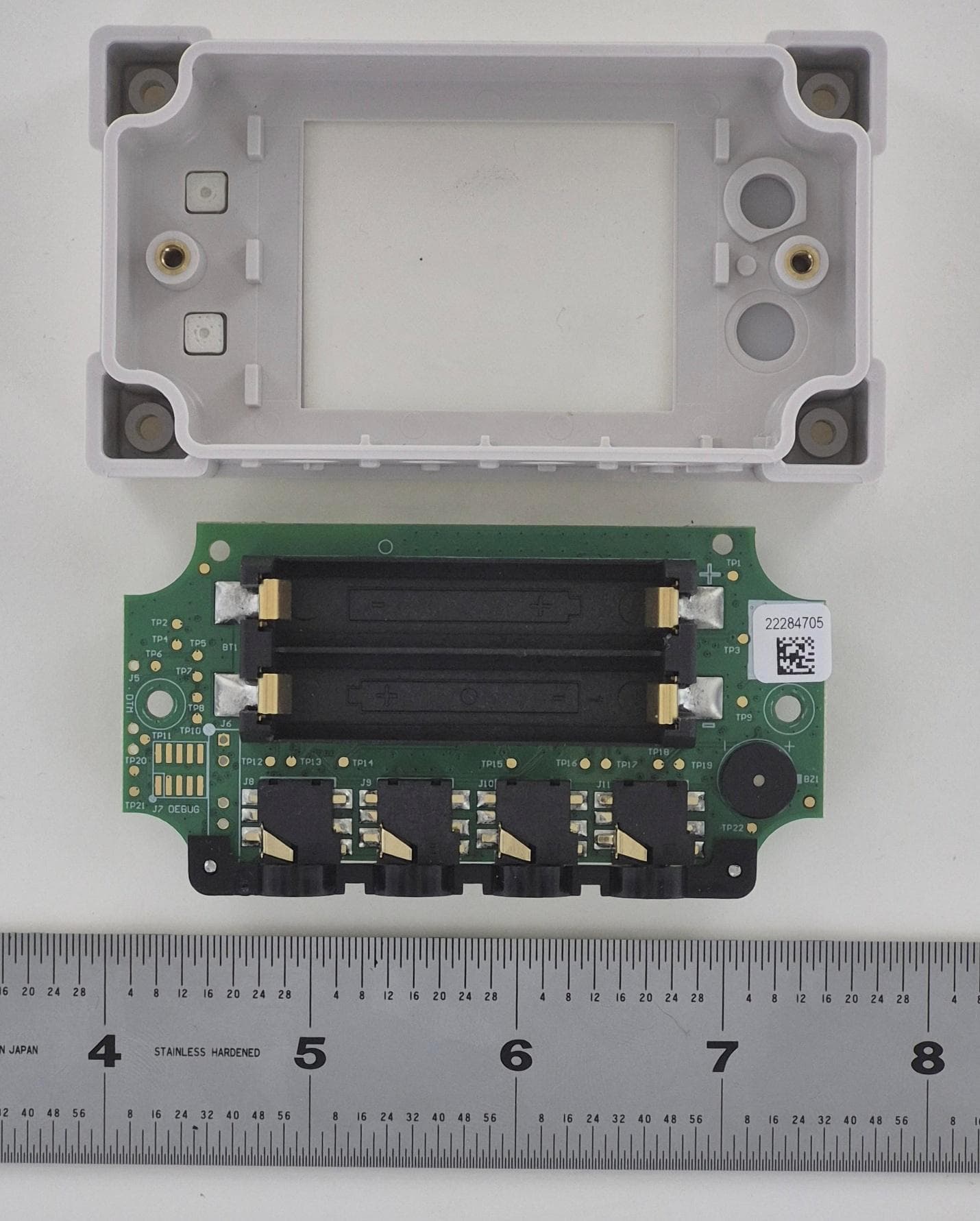
Dec 17, 2025HOBO MX Analog/Temp/RH/Light Data Logger, InTemp CX460 4-Channel Analog Data logger
Equipment Class
DTS - Digital Transmission System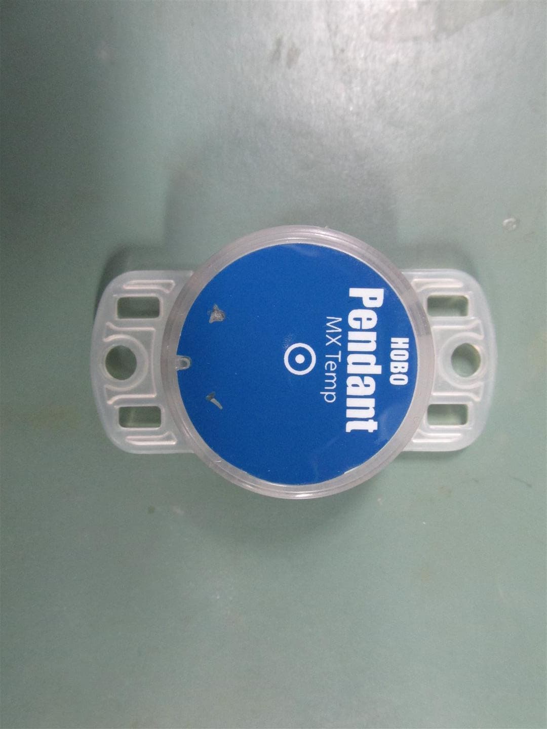
WXF-ONST4
Aug 16, 2020HOBO Pendant MX Loggers
Equipment Class
DTS - Digital Transmission System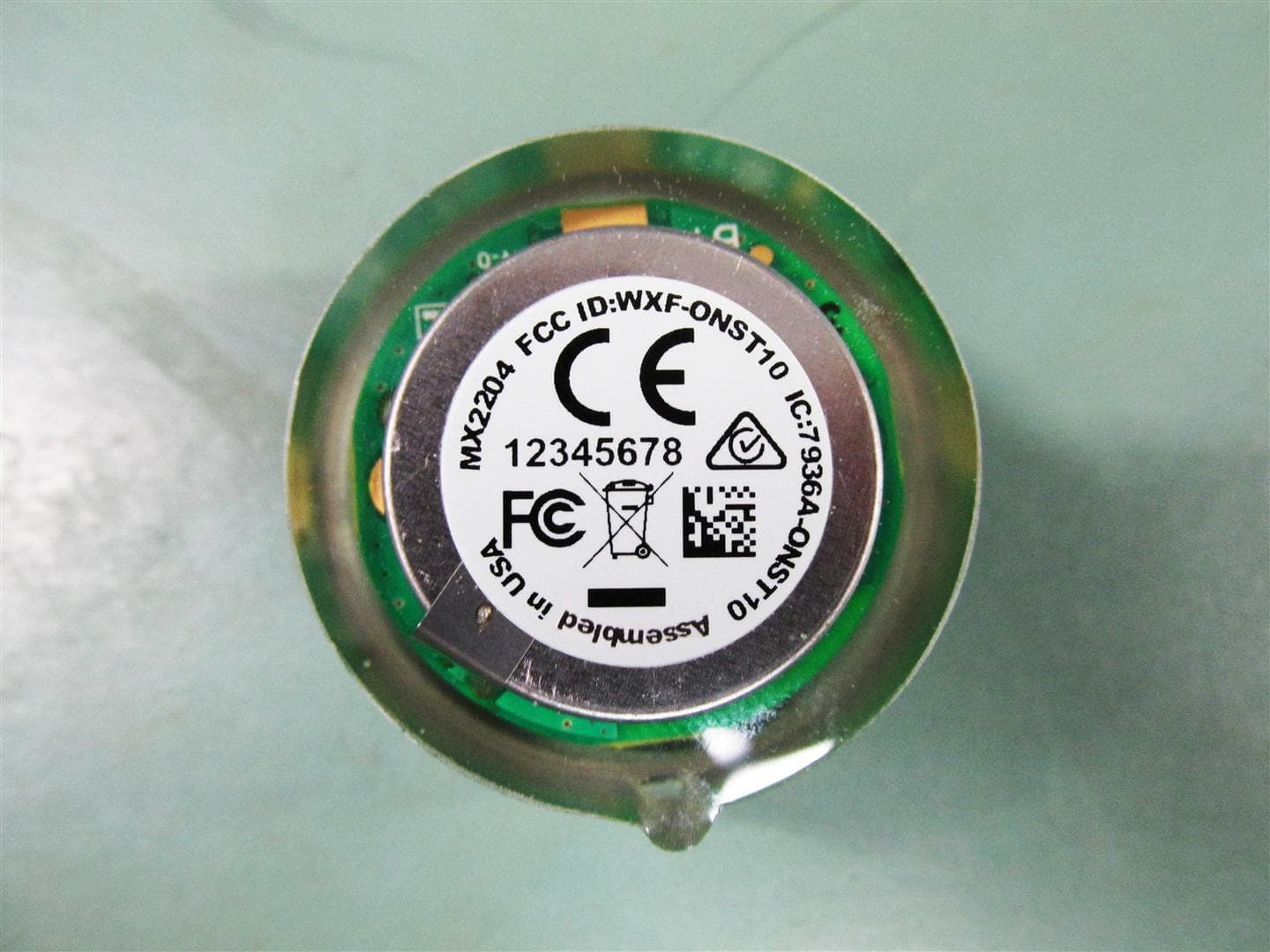
WXF-ONST10
Aug 16, 2020HOBO TidbiT MX Loggers
Equipment Class
DTS - Digital Transmission System
WXF-ONST1
Jun 03, 2015Digital Transmission
Equipment Class
DTS - Digital Transmission System
WXF-MX1101
Jul 22, 2014Relative Humidity Data Logger
Equipment Class
DTS - Digital Transmission System