WXF-ONST8HOBO MX Analog/Temp/RH/Light Data Logger, InTemp CX460 4-Channel Analog Data logger
Onset Computer Corporation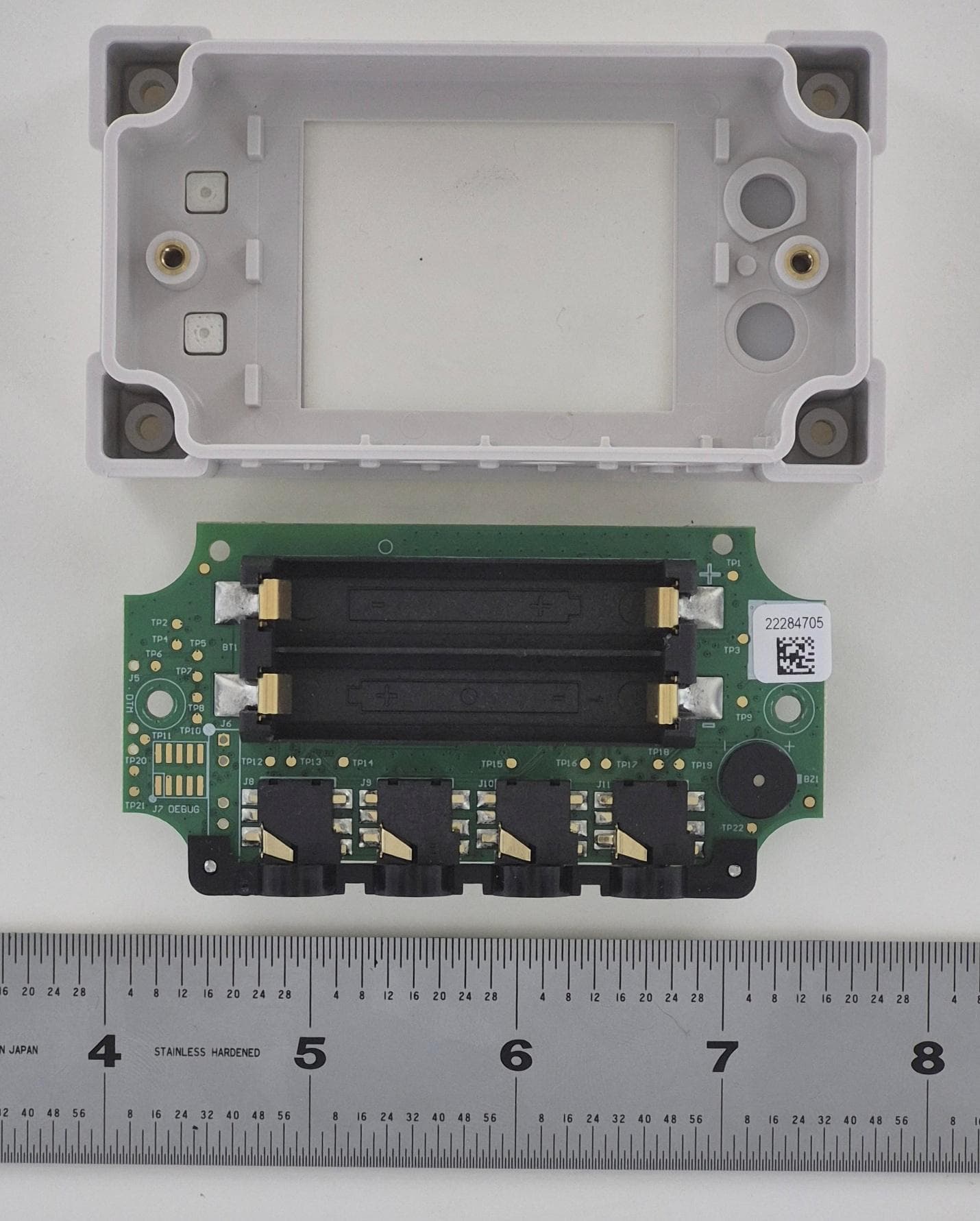
Click to zoom
Application Details
- Equipment Class
- DTS - Digital Transmission System
- Date of Grant
- Dec 17, 2025
- Application Purpose
- Original Equipment
- Equipment Note
- HOBO MX Analog/Temp/RH/Light Data Logger, InTemp CX460 4-Channel Analog Data logger
- Frequency Range
- 2402.00000000 - 2480.00000000
- Company
- Onset Computer Corporation
- Country
- United States
Documents & Files
Document Text
Text extracted from the exhibit documents filed with the FCC. Open a document above to read the original.
Users Manual
29123-A1 InTemp CX460 Data Logger Models: • 4- Channel Analog (CX460) Included Items: • Two AAA 1.5 V alkaline batteries (installed) Required Items: • InTemp app • Mobile device with Bluetooth and iOS, iPadOS®, or Android™, The InTemp CX 4-Channel Analog (CX460) data logger measures and transmits data wirelessly to a mobile device using Bluetooth® Low Energy (BLE) technology. The CX460 has four analog inputs and supports a wide variety of external sensors (sold separately), including self- describing temperature, split-core AC current transformer, 4- 20 mA input, and DC voltage input sensors. The self-describing sensors are designed with integrated strain relief for a secure connection to the loggers and are automatically detected by the InTemp® app for easy setup. Using the app, you can configure the loggers, read out and view data, and export the data for further analysis. The loggers can calculate minimum, maximum, average, and standard deviation statistics and can also be configured to trip audible or visual alarms at thresholds you specify. This compact logger also has a built-in LCD screen to display current sensor readings, logging status, battery use, memory consumption, and more. Specifications InTemp® CX 4-Channel Analog CX460 Data Logger User Guide Logger Operating Range -20° to 70°C (-4° to 158°F) Radio Power 1 mW (0 dBm) Transmission Range Approximately 30.5 m (100 ft) line-of-sight Wireless Data Standard Bluetooth Low Energy Logging Interval 1 second to 18 hours Start Modes Start now, on interval, on button push, after elapsed time, or date & time Time Accuracy ±1 minute per month at 25°C (77°F) Battery Type Two AAA 1.5 V alkaline batteries, user replaceable Battery Life 1 year, typical with logging interval of 1 minute and Bluetooth Always On enabled; 2 years, typical with logging interval of 1 minute and Bluetooth Always On disabled; and temperatures between 0° and 50°C (32° and 122°F). Faster logging intervals and statistics sampling intervals, burst logging, remaining connected with the app, excessive downloads, and paging may impact battery life. Memory 4 MB (1.9 million measurements, maximum) Full Memory Download Time Approximately 4 to 15 minutes depending on the mobile device; may take longer the further the device is from the logger LCD LCD is visible from 0° to 50°C (32° to 122°F); the LCD may react slowly or go blank in temperatures outside this range Size 11.28 x 5.41 x 2.92 cm (4.44 x 2.13 x 1.15 in.) Weight 123 g (4.34 oz) Environmental Rating IP54 See last page InTemp CX 4-Channel Analog (CX460) Manual U.S. and International Sales: 1-508-743-3309 2 www.onsetcomp.com Logger Components and Operation Self-Describing Sensor Mounting Loop Analog Sensor Port: Use this 2.5 mm jack to connect a self- describing sensor or other analog sensor. The CX460 has four ports. Top Button: Press this button for 3 seconds to start logging (if the logger is configured with the Start On Button Push option). This requires configuring the logger in the app with a logger profile that has Start on Button Push selected for the start mode (see Configure the Logger). You can also press the top button for 1 second to wake up the logger, bring the logger to the top of the list in the app, cycle through each channel on the LCD, and silence a beeping alarm (see Logger Alarms). Bottom Button: You can press this button for 1 second to wake up the logger or silence a beeping alarm. Press both the top and bottom buttons simultaneously for 10 seconds to reset a logger password. Self-Describing Sensor: This is a type of external sensor available for CX460loggers. Turn the sensor plug one-quarter clockwise when inserting it into an analog sensor port to secure it in place. This sensor also features automatic detection by the logger (see Working with External Sensors). Plug: Use this Santoprene® (TPE) plug to fill an empty analog sensor port. Mounting Loops: Use the two mounting loops (only one visible in the diagrams) to mount the logger (see Mounting the Logger). LCD Screen: This logger is equipped with an LCD screen that displays details about the current status. This example shows all symbols illuminated on the LCD screen followed by definitions of each symbol. LCD Screen Plug LCD Symbol Description The logger is waiting to be started or restarted. Press and hold the top button for 3 seconds to start the logger; the logger also displays HOLD during this time. The logger displays HOLD when you press the top button for 3 seconds to start the logger, or while pressing the bottom button for 3 seconds to clear an alarm. The logger displays NEXT when it is logging more than one. Press the top button to cycle through each channel to view sensor measurements. The battery indicator shows the approximate battery power remaining. The logger is set to Stop When Memory Fills. The memory bar indicates the approximate amount of storage space remaining in the logger. When the logger first starts logging data, all five segments are empty. The logger is currently logging. The bell icon indicates a sensor alarm has tripped. Press the top button to view the channel with the alarm icon. This indicates a problem with an external sensor. See Working with External Sensors for more details. This is an example of a sensor reading, with the latest reading displayed above the unit type for that sensor. To switch between US and SI units, change the units in the Settings area of the app (reconfigure the logger to have your unit’s changes take effect). Note: If the sensor value exceeds five digits, the scientific notation E3 is appended to the value on the LCD to signify that the displayed digits are multiplied by 1,000 The logger has been configured to start logging on a particular date/time. The display counts down in days, hours, minutes, and seconds until logging begins. In this example, 5 minutes and 38 seconds remain until logging begins. The configuration settings are being loaded onto the logger from the app. The logg…
Text truncated - open the document above for the full version.
Users Manual
HOBO® MX Analog/Temp/RH/Light (MX1104) and MX 4‐Channel Analog (MX1105) Data Logger Manual 23968‐B The HOBO MX Analog/Temp/RH/Light (MX1104) and HOBO MX 4‐Channel Analog (MX1105) data loggers measure and transmit data wirelessly from indoor environments to mobile devices using Bluetooth® Low Energy technology. The MX1104 model has integrated temperature, relative humidity (RH), and light intensity sensors and one analog input while the MX1105 model has four analog inputs. Both models support a wide variety of external sensors (sold separately), including self‐describing temperature, split‐core AC current transformer, 4‐20 mA input, and DC voltage input sensors. The self‐describing sensors are designed with integrated strain relief for a secure connection to the loggers and are automatically detected by the HOBOmobile app for easy setup. Using the app, you can configure the loggers, read out and view data, and export the data for further analysis. The loggers can calculate minimum, maximum, average, and standard deviation statistics and can also be configured to trip audible or visual alarms at thresholds you specify. In addition, both loggers support burst logging in which data is logged at a different interval when sensor readings are above or below certain limits. These compact loggers also have built‐in LCD screens to display current sensor readings, logging status, battery use, memory consumption, and more. Specifications Temperature Sensor (MX1104) Range ‐20° to 70°C (‐4° to 158°F) Accuracy ±0.20°C from 0° to 50°C (±0.36°F from 32° to 122°F) Resolution 0.002°C at 25°C (0.004°F at 77°F) Drift <0.1°C (0.18°F) per year RH Sensor* (MX1104) Range 0% to 100% at ‐20° to 70°C (‐4° to 158°F); exposure to conditions above 95% may temporarily increase the maximum RH sensor error by an additional 1% Accuracy ±2.5% from 10% to 90% (typical) to a maximum of ±3.5% including hysteresis at 25°C (77°F); below 10% and above 90% ±5% typical Resolution 0.01% Drift <1% per year typical Response Time (MX1104) Temperature 11 minutes in air moving 1 m/s (2.2 mph) RH 30 seconds to 90% in airflow of 1 m/s (2.2 mph) Light Sensor (M1104) Range 0 to 167,731 lux (15,582 lum/ft 2 ) Accuracy ±10% typical for direct sunlight (see Light Measurement on page 4 for more details) Logger with Cable Type SD‐MA‐420 or CABLE‐4‐ 20mA SD‐VOLT‐2.5 or CABLE‐2.5‐ STEREO SD‐VOLT‐05 or CABLE‐ ADAP5 SD‐VOLT‐10 or CABLE‐ ADAP10 SD‐VOLT‐24 or CABLE‐ ADAP24 Measurement Range 0 to 20.1 mA 0 to 2.5 V 0 to 5.0 V 0 to 10 V 0 to 24 V Accuracy ±0.001 mA ±0.2% of reading ±0.1 mV ±0.1% of reading ±0.2 mV ±0.3% of reading ±0.4 mV ±0.3% of reading ±1.0 mV ±0.3% of reading Resolution 0.3 μA 40 μV 80 μV 160 μV 384 μV Logger Operating Range ‐20° to 70°C (‐4° to 158°F) Radio Power 1 mW (0 dBm) HOBO MX1104 and MX1105 Data Loggers Models: Analog/Temp/RH/Light (MX1104) 4‐Channel Analog (MX1105) Included Items: Tie wraps Two AAA 1.5 V alkaline batteries (installed) Required Items: HOBOmobile app Device with iOS and Bluetooth MX1105 Model Shown HOBO MX Analog/Temp/RH/Light (MX1104) and MX 4‐Channel Analog (MX1105) Manual 1‐800‐LOGGERS 2 www.onsetcomp.com Specifications (continued) Transmission Range Approximately 30.5 m (100 ft) line‐of‐sight Wireless Data Standard Bluetooth Low Energy (Bluetooth Smart) Logging Rate 1 second to 18 hours Logging Modes Fixed interval (normal, statistics) or burst Memory Modes Wrap when full or stop when full Start Modes Immediate, push button, date & time, or next interval Stop Modes When memory full, push button, date & time, or after a set logging period Restart Mode Push button Time Accuracy ±1 minute per month at 25°C (77°F) Battery Type Two AAA 1.5 V alkaline batteries, user replaceable Battery Life 1 year, typical with logging interval of 1 minute and Bluetooth Always On enabled; 2 years, typical with logging interval of 1 minute and Bluetooth Always On disabled; and temperatures between 0° and 50°C (32° and 122°F). Faster logging intervals and statistics sampling intervals, burst logging, remaining connected with the app, excessive downloads, and paging may impact battery life. Memory 4 MB (1.9 million measurements, maximum) Full Memory Download Time Approximately 4 to 15 minutes depending on the mobile device; may take longer the further the device is from the logger LCD LCD is visible from 0° to 50°C (32° to 122°F); the LCD may react slowly or go blank in temperatures outside this range Size 11.28 x 5.41 x 2.92 cm (4.44 x 2.13 x 1.15 in.) Weight 123 g (4.34 oz) Environmental Rating IP54 The CE Marking identifies this product as complying with all relevant directives in the European Union (EU). See last page *Per RH sensor manufacturer data sheet Logger Components and Operation RH Sensor: This sensor is located in the upper left corner and to the left of the LCD screen in the MX1104 model. Light Sensor: This sensor is located below the RH sensor and to the left of the LCD screen in the MX1104 model. Temperature Sensor: This sensor is located in the bottom left corner and to the left of the LCD screen in the MX1104 model. A small pipe protrudes from the bottom side of the logger case to vent the temperature sensor. Analog Sensor Port: Use this 2.5 mm jack to connect a self‐ describing sensor or other analog sensor. The MX1104 model has one port and the MX1105 model has four ports. Top Button: Press this button for 3 seconds to start or stop logging data, or to resume logging on the next even logging interval. This requires configuring the logger in HOBOmobile with a push button start or stop, and with Allow Button Restart selected (see Setting up the Logger). MX1104 Model Analog Sensor Port Bottom Button Top Button Light Sensor Temperature Sensor (internal) and Venting Pipe Mounting Loop Self‐Describing Sensor Plug LCD Screen MX1105 Model RH Sensor HOBO MX Analog/Temp/RH/Light (MX1104) and MX 4‐Channel Analog (MX1105) Manual 1‐800‐LOGGERS 3 www.onsetcomp.com You can also press the top button for 1 second…
Text truncated - open the document above for the full version.
Test Setup Photos
FCC ID: WXF-ONST8 IC: 7936A-ONST8 Model MX1104 for Pre-Scan X-Axis Y-Axis FCC ID: WXF-ONST8 IC: 7936A-ONST8 Z-Axis Worst-Case Model MX1105 for Final Testing X-Axis FCC ID: WXF-ONST8 IC: 7936A-ONST8 Y-Axis (Worst-case orientation) Z-Axis FCC ID: WXF-ONST8 IC: 7936A-ONST8 9k-30MHz Front 9k-30MHz Rear FCC ID: WXF-ONST8 IC: 7936A-ONST8 30MHz-1GHz Front 30MHz-1GHz Rear FCC ID: WXF-ONST8 IC: 7936A-ONST8 1-18GHz Front 1-18GHz Rear FCC ID: WXF-ONST8 IC: 7936A-ONST8 18-25GHz Front 18-25GHz Rear FCC ID: WXF-ONST8 IC: 7936A-ONST8 Model MX1105 Antenna Port Measurements Test Setup EUT Close-up 1 FCC ID: WXF-ONST8 IC: 7936A-ONST8 EUT Close-up 2 Conducted Spurious Emissions
Test Report
2.4GHz Chip Antenna, SMD, AEC-Q200 Qualified Detail Specification: Page 1 of 5 ±± ±± ±± ±± ±± https://www.johansontechnology.com 4001 Calle Tecate • Camarillo, CA 93012 • TEL 805.389.1166 FAX 805.389.1821 Ver. 1.2 2020 Johanson Technology, Inc. All Rights Reserved mm e.g. 2450AT43B100E-AEC e.g. 2450AT43B100S-AECSuffix = S Part Number Explanation Return Loss (dB) 9.5 min. Peak Gain (dBi) 1.3 typ. Average Gain (dBi) -0.5 typ. Impedance (Ω) Input Power (W) Recommended Storage Conditions and Period for unused T&R Product +5 to +35°C Humidity 45 - 75% RH 50 2 max. (CW) 4 Terminal Configuration Function FEED 1 FEED 2 NC No. 1 2 3 NC a 0.0200.0120.500.3 W1 0.0200.0080.500.2 T 0.0792.00+0.1 / -0.2+0.004 / -0.008 0.0790.0082.000.2 L1 0.1022.600.20.008 Johanson Technology, Inc. reserves the right to make design changes without notice. All sales are subject to Johanson Technology, Inc. terms and conditions. e.g. 2450AT43B100(E or S)-AEC100% Tin Packing Style Evaluation Board 2450AT43B100-EB1SMA Bulk (loose) T&R Suffix = E or S Suffix = E P/N Suffix Mechanical Dimensions In L 0.2760.0087.000.2 W 18 months max. Frequency (GHz) 2.4 - 2.5 Reel Quantity (pcs/reel) 1000 Operating Temperature -40 to +105°C High Frequency Ceramic Solutions Part Number 6/29/2021 Let us help you with the antenna design, optimization, and tuning! 2450AT43B100E-AEC General Specifications P/N 2450AT43B100E-AEC Bottom Top View Side View L W L1W1 Bottom View a T 2.4GHz Chip Antenna, SMD, AEC-Q200 QualifiedP/N 2450AT43B100E-AEC Detail Specification: Page 2 of 5 https://www.johansontechnology.com 4001 Calle Tecate • Camarillo, CA 93012 • TEL 805.389.1166 FAX 805.389.1821 Ver. 1.2 2020 Johanson Technology, Inc. All Rights Reserved "High Frequency Ceramic Solutions" 6/29/2021 Mounting Considerations 1: Evaluation Board Johanson Technology, Inc. reserves the right to make design changes without notice. All sales are subject to Johanson Technology, Inc. terms and conditions. Would you like the layout file? Contact our engineers at: https://www.johansontechnology.com/ask-a-question 0.83 2.81 1.6 1.6 1 0.8 1.83 0.8 1 2 22 10 4.87 * 1.8nH 2.7nH ) ) 4.87 40 20 Ground No Ground 10 Antenna Units in mm *50ΩGCPW transmission line recommended Note 1: Pins 2, 3 & 4, although "NC", must be soldered to their corresponding PCB pads for proper electrical operation 2.4GHz Chip Antenna, SMD, AEC-Q200 QualifiedP/N 2450AT43B100E-AEC Detail Specification: Page 3 of 5 https://www.johansontechnology.com 4001 Calle Tecate • Camarillo, CA 93012 • TEL 805.389.1166 FAX 805.389.1821 Ver. 1.2 2020 Johanson Technology, Inc. All Rights Reserved "High Frequency Ceramic Solutions" 6/29/2021 Mounting Considerations 1: Electrical Performance @25°C Johanson Technology, Inc. reserves the right to make design changes without notice. All sales are subject to Johanson Technology, Inc. terms and conditions. Measured Return Loss Have antenna tuning issues? Please contact us if you have any questions regarding the implementation of this antenn a in your PCB's layout. We'll be happy to guide you to maximize the antenna's performance Contact our applications engineers at: https://www.johansontechnology.com/ask-a-question 2.4GHz Chip Antenna, SMD, AEC-Q200 QualifiedP/N 2450AT43B100E-AEC Detail Specification: Page 4 of 5 https://www.johansontechnology.com 4001 Calle Tecate • Camarillo, CA 93012 • TEL 805.389.1166 FAX 805.389.1821 Ver. 1.2 2020 Johanson Technology, Inc. All Rights Reserved "High Frequency Ceramic Solutions" 6/29/2021 Mounting Considerations 1: Antenna Performance Johanson Technology, Inc. reserves the right to make design changes without notice. All sales are subject to Johanson Technology, Inc. terms and conditions. Typical 2D radiation patterns @ 2.45GHz YZ‐plane XZ‐plane XY‐plane θ φ +Z (θ= 0°) θ +Z +Z +X -Z +Y (θ= 90°) -Y -Z +Z (θ= 0°) +X (θ= 90°) -X -Z -Z +Y -Y +X -X +Y -Y -X +X (φ= 0°) -X +Y (φ= 90°) -Y Vertical Horizontal Vertical Horizontal Vertical Horizontal 2.4GHz Chip Antenna, SMD, AEC-Q200 QualifiedP/N 2450AT43B100E-AEC Detail Specification: Page 5 of 5 https://www.johansontechnology.com 4001 Calle Tecate • Camarillo, CA 93012 • TEL 805.389.1166 FAX 805.389.1821 Ver. 1.2 2020 Johanson Technology, Inc. All Rights Reserved "High Frequency Ceramic Solutions" Antenna tuning, optimization, and validation services: https://www.johansontechnology.com/ipc-antenna-services For more antennas and to download measured S-parameters, go to: 6/29/2021 Johanson Technology, Inc. reserves the right to make design changes without notice. All sales are subject to Johanson Technology, Inc. terms and conditions. https://www.johansontechnology.com/antennas Soldering Information https://www.johansontechnology.com/ipcsoldering-profile MSL Info https://www.johansontechnology.com/msl-rating https://www.johansontechnology.com/rohs-compliance Packaging Information https://www.johansontechnology.com/tape-reel-packaging For layout review contact our applications team at: https://www.johansontechnology.com/ask-a-question RoHS Compliance Need help designing the antenna in? Use our antenna design services! https://www.johansontechnology.com/ipc-antenna-services We provide 2 free layout reviews and if you need us to tune and characterize the antenna on your product (inside anechoic chamber) we can do that too. Small lab fee may apply for the latter.
Test Report
Bureau Veritas Consumer Product Services Inc. One Distribution Center Circle, #1 Littleton, MA Tel.: (978) 486-8880 Fax: (978) 486-8828 Page 1 of 52 Test Report for Onset Computer Corporation Report No. EY0826-1 Issue 5 TEST REPORT Applicant Onset Computer Corporation Address 470 MacArthur Blvd. Bourne, MA 02532 FCC ID WXF-ONST8 ISED Canada IC 7936A-ONST8 Product Marketing Name (PMN) MX1104: HOBO ® MX Analog/Temp/RH/Light Data Logger MX1105: HOBO ® MX 4-Channel Analog Data Logger CX460: InTemp ® CX 4-Channel Analog Data Logger Model Name or Number MX1104, MX1105 and CX460 Hardware Version Identification Number (HVIN) MX1104, MX1105, CX460 Firmware Version Identification Number (FVIN) 59 Model Differences See Section 3.1 of this report for more details Date of tests Oct 22-28, 2024 FCC Test Firm DN Canada CABID US1028 US0106 The tests have been carried out according to the requirements of the following standard: FCC Part 15, Subpart C, Section 15.247 ISED Canada RSS-247 Issue 3 CONCLUSION: The submitted sample was found to COMPLY with the test requirement Prepared by Nisha Patel Wireless Engineer I Approved by Yunus Faziloglu EMC Manager Report Issue Date: Aug 25, 2025 Issue Number: 5 This report is governed by, and incorporates by reference, CPS Conditions of Service as posted at the date of issuance of this report at https://www.cps.bureauveritas.com/terms-conditions and is intended for your exclusive use. Any copying or replication of this report to or for any other person or entity, or use of our name or trademark, is permitted only with our prior written permission. This report sets forth our findings solely with respect to the test samples identified herein. The results set forth in this report are not indicative or representative of the quality or characteristics of the lot from which a test sample was taken or any similar or identical product unless specifically and expressly noted. Our report includes all of the tests requested by you and the results thereof based upon the information that you provided to us. Measurement uncertainty is only provided upon request for accredited tests. You have 60 days from date of issuance of this report to notify us of any material error or omission caused by our negligence or if you require measurement uncertainty; provided, however, that such notice shall be in writing and shall specifically address the issue you wish to raise. A failure to raise such issue within the prescribed time shall constitute you unqualified acceptance of the completeness of this report, the tests conducted and the correctness of the report contents. Bureau Veritas Consumer Product Services Inc. One Distribution Center Circle, #1 Littleton, MA Tel.: (978) 486-8880 Fax: (978) 486-8828 Page 2 of 52 Test Report for Onset Computer Corporation Report No. EY0826-1 Issue 5 TABLE OF CONTENTS RELEASE CONTROL RECORD ....................................................................................................................... 4 1 SUMMARY OF TEST RESULTS .............................................................................................................. 5 2 MEASUREMENT UNCERTAINTY ......................................................................................................... 6 3 GENERAL INFORMATION ..................................................................................................................... 7 3.1 GENERAL DESCRIPTION OF EUT ............................................................................................. 7 3.2 DESCRIPTION OF TEST MODES ............................................................................................... 8 3.3 MEASUREMENT PROCEDURES USED .................................................................................. 10 3.4 DESCRIPTION OF SUPPORT EQUIPMENT ............................................................................. 10 4 TEST RESULTS ......................................................................................................................................... 11 4.1 RADIATED SPURIOUS EMISSIONS .......................................................................................... 11 4.1.1 LIMITS ........................................................................................................................................... 11 4.1.2 TEST EQUIPMENT USED ........................................................................................................... 12 4.1.3 TEST PROCEDURES ................................................................................................................... 13 4.1.4 DEVIATIONS ................................................................................................................................ 14 4.1.5 TEST SETUP ................................................................................................................................. 14 4.1.6 EUT OPERATING CONDITIONS ................................................................................................ 15 4.1.7 TEST RESULTS ............................................................................................................................. 16 4.2 6DB CHANNEL BANDWIDTH & 99% OBW ................................................................................ 33 4.2.1 LIMITS .......................................................................................................................................... 33 4.2.2 TEST SETUP ................................................................................................................................. 33 4.2.3 TEST EQUIPMENT USED ........................................................................................................... 33 4.2.4 TEST PROCEDURES ................................................................................................................... 33 4.2.5 DEVIATIONS ..................................................................................…
Text truncated - open the document above for the full version.
RF Exposure Info
Bureau Veritas Consumer Product Services, Inc. Test Report Number: One Distribution Center Circle #1, Littleton, MA 01460 Y0826-2 Issue 2 Page 1 of 6 Template Version 2023-01-09 CFR Title 47 FCC Parts 1.1307, 1.1310, 2.1091 RF Exposure Exhibit Prepared for Onset Computer Corporation Model: MX1105 Hardware Version: MX1104, MX1105, CX460 Prepared by Nisha Patel Wireless Engineer I Approved by Yunus Faziloglu EMC Manager Issue Date: Aug 19, 2025 Issue Number: 2 This test result relates only to the described test object. This document shall not be reproduced, except in full, without the written approval of Bureau Veritas Test Lab. Customer must not use this test report as the product certification of each accreditation body or each national organization. The test is traceable to national standard or related international standard Bureau Veritas Consumer Product Services, Inc. Test Report Number: One Distribution Center Circle #1, Littleton, MA 01460 Y0826-2 Issue 2 Page 2 of 6 Template Version 2023-01-09 Contents 1 Device Under Test ....................................................................................................................................3 2 Test Laboratory Information .....................................................................................................................4 3 RF Exposure Limit .....................................................................................................................................5 4 RF Exposure – MPE Evaluation ..................................................................................................................6 5 Conclusion ...............................................................................................................................................6 Bureau Veritas Consumer Product Services, Inc. Test Report Number: One Distribution Center Circle #1, Littleton, MA 01460 Y0826-2 Issue 2 Page 3 of 6 Template Version 2023-01-09 1 Device Under Test 1.1 Product Information Project Number: EY0826 Applicant Information: Onset Computer Corporation 470 Mac Arthur Blvd. Bourne, MA 02535 Model: MX1105 Hardware Version MX1104, MX1105, CX460 Additional Models MX1104, CX460 Model differences: As described in EY0826-1 Test Report Separation Distance: 20cm Exposure Category of DUT: Mobile Multiple Simultaneous RF Sources: No Type of Evaluation: MPE Calculation Evaluation Method: 447498 D01 General RF Exposure Guidance v06 Deviations from Standard: None 1.2 Technical Information Radio Description BLE FCC ID: WXF-ONST8 Exposure Category of Transmitter: Mobile Maximum Conducted Output Power (mW): 0.27mW (Average) Maximum Tune-up Tolerance (dB): N/A Maximum Antenna Gain (dBi): 1.3dBi Bureau Veritas Consumer Product Services, Inc. Test Report Number: One Distribution Center Circle #1, Littleton, MA 01460 Y0826-2 Issue 2 Page 4 of 6 Template Version 2023-01-09 2 Test Laboratory Information Location of Test Lab: One Distribution Center Circle #1 Littleton, MA 01460 (978) 486-8880 Key Contact: Yunus Faziloglu [email protected] Laboratory Accreditations: BUREAU VERITAS CONSUMER PRODUCTS SERVICES, INC is accredited in accordance with the recognized International Standard ISO/IEC 17025:2017 General requirements for the competence of testing and calibration laboratories. ISO/IEC 17025:2017: 1627-01 FCC Test Site Number: US1028 Bureau Veritas Consumer Product Services, Inc. Test Report Number: One Distribution Center Circle #1, Littleton, MA 01460 Y0826-2 Issue 2 Page 5 of 6 Template Version 2023-01-09 3 RF Exposure Limit: According to CFR Title 47 FCC section 1.1310, the criteria listed in the following table shall be used to evaluate Maximum Permissible Exposure (MPE) to radiofrequency electromagnetic fields. Bureau Veritas Consumer Product Services, Inc. Test Report Number: One Distribution Center Circle #1, Littleton, MA 01460 Y0826-2 Issue 2 Page 6 of 6 Template Version 2023-01-09 4 RF Exposure – MPE Evaluation 5 Conclusion EUT complies with FCC section 1.1310 MPE limits for general population as a mobile device. Document Revisions Issue No. Summary of Changes Date Issued Prepared by Approved by 1 Original Release Nov 5, 2024 YF AA 2 To address TCB review comments: - HVIN information updated on the Cover page and in section 1.1. Aug 19, 2025 NP YF End of Report Prediction of MPE limit at a given distance Equation from page 18 of OET Bulletin 65, Edition 97-01 where: S = power density P = power input to the antenna G = power gain of the antenna in the direction of interest relative to an isotropic radiator R = distance to the center of radiation of the antenna Maximum peak output power at the antenna terminal: -5.622(dBm) Maximum peak output power at the antenna terminal:0.27(mW) Antenna gain(typical):1.3(dBi) Maximum antenna gain: 1.35(numeric) Prediction distance:20(cm) Prediction frequency:2402(MHz) MPE limit for uncontrolled exposure at prediction frequency: 1(mW/cm^2) Power density at prediction frequency:0.000074(mW/cm^2) 2 4R PG S p =
Internal Photos
Page 14 MX1105 PCB Back Page 15 MX1105 PCB Front w/ LCD Page 16 MX1105 PCB Front & LCD Removed Page 17 MX1105 LCD Page 18 MX1105 PCB Front Page 19 MX1105 Radio Page 20 MX1105 Antenna Page 21 MX1105 PCB Bottom Page 22 MX1105 PCB Bottom w/ No Connector Shroud Page 23 MX1105 Connector Shroud Page 24 MX1105 Exploded View
Internal Photos
Page 13 MX1104 PCB Front w/ LCD & Daughter Board Page 14 MX1104 Housing & PCB Front Daughter Board Removed Page 15 MX1104 PCB Front & LCD Page 16 MX1104 PCB Front LCD Removed Page 17 MX1104 LCD Page 18 MX1104 PCB Front Page 19 MX1104 PCB Back Page 20 MX1104 Radio Page 21 MX1104 Antenna Page 22 MX1104 PCB Bottom Page 23 MX1104 PCB Bottom No Connector Shroud Page 24 MX1104 Connector Shroud Page 25 MX1104 Daughter Board Top Page 26 MX1104 Daughter Board Bottom Page 27 MX1104 Exploded View
Internal Photos
Page 14 CX460 PCB Front w/ LCD Page 15 CX460 PCB Front & LCD Removed Page 16 CX460 LCD Page 17 CX460 PCB Front Page 18 CX46…
Text truncated - open the document above for the full version.
Contact Information
Applicant
James Corrigan
[email protected]Fax: 508-759-9100
Technical Contact
Onset Computer CorporationJames W. Corrigan
470 MacArthur Blvd. · Bourne, Massachusetts, 02532 · United States
Test Firm
BUREAU VERITAS CONSUMER PRODUCTS SERVICES, INC.Syed Hussain
Technical Specifications
| # | Rule Parts | Frequency Range | Power Output |
|---|---|---|---|
| 1 | 15C | 2.40 GHz - 2.48 GHz | 270.00 µW |
Other Applications from Onset Computer Corporation
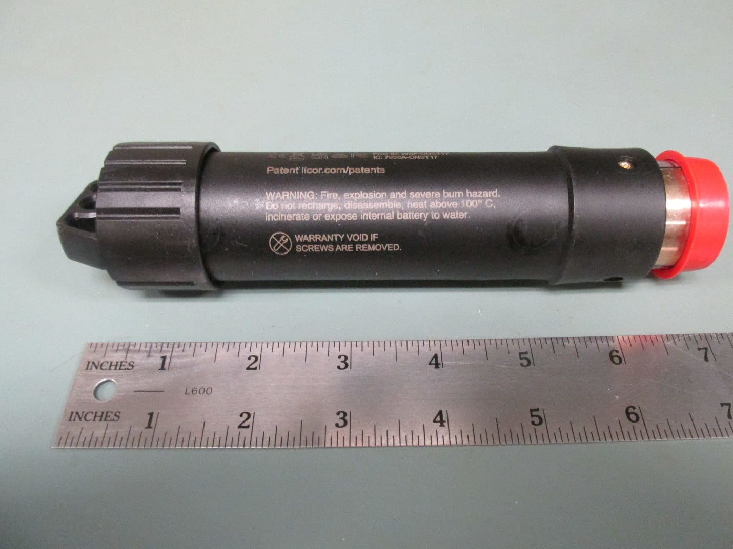
WXF-ONST17
Jun 29, 2026HOBO MX Underwater PAR Data Logger
Equipment Class
DTS - Digital Transmission System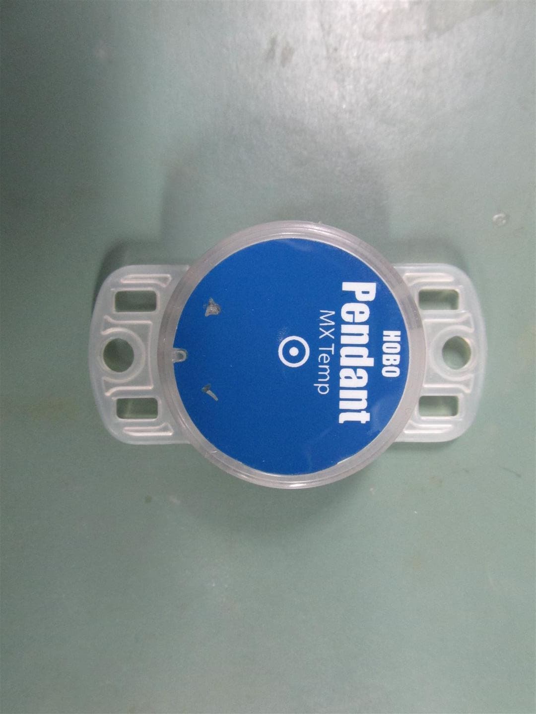
WXF-ONST4
Aug 16, 2020HOBO Pendant MX Loggers
Equipment Class
DTS - Digital Transmission System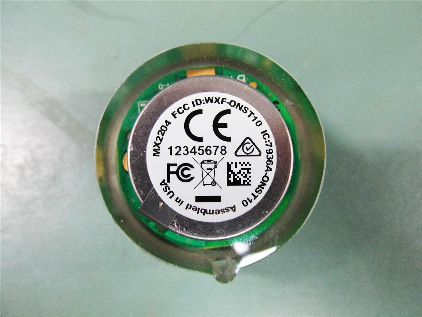
WXF-ONST10
Aug 16, 2020HOBO TidbiT MX Loggers
Equipment Class
DTS - Digital Transmission System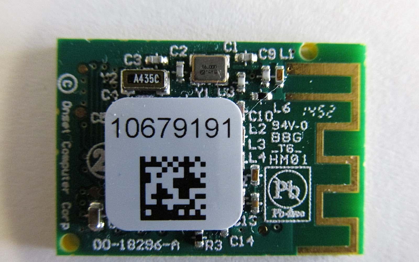
WXF-ONST1
Jun 03, 2015Digital Transmission
Equipment Class
DTS - Digital Transmission System
WXF-MX1101
Jul 22, 2014Relative Humidity Data Logger
Equipment Class
DTS - Digital Transmission System