WY7-SWAN1Wireless Module
SHIMANO INC.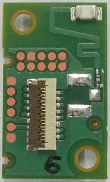
Click to zoom
Application Details
- Equipment Class
- DXX - Part 15 Low Power Communication Device Transmitter
- Date of Grant
- May 21, 2012
- Application Purpose
- Original Equipment
- Date of Application
- May 15, 2012
- Equipment Note
- Wireless Module
- Frequency Range
- 2403.00000000 - 2480.00000000
- Company
- SHIMANO INC.
- Country
- Japan
Documents & Files
Document Text
Text extracted from the exhibit documents filed with the FCC. Open a document above to read the original.
Users Manual
8 May 2012 Rev.E SHIMANO INC. Confidential SHIMANO INC. 1/11 SWAN-1 Wireless Module SWAN-1 User’s Manual 8 May 2012 Rev.E SHIMANO INC. Confidential SHIMANO INC. 2/11 SWAN-1 TABLE OF CONTENTS Introduction................................................ 3 General description................................... 3 Block diagram............................................ 3 Software install........................................... 4 Operating procedure.................................. 4 - 6 Regulatory information.............................. 7 - 11 Rev. Record 07 Mar. 2012> Rev A 03 Apr. 2012> Rev B 23 Apr. 2012> Rev C 26 Apr. 2012> Rev D 08 May 2012> Rev E 8 May 2012 Rev.E SHIMANO INC. Confidential SHIMANO INC. 3/11 SWAN-1 Introduction This document describes the system operation of SWAN-1 –ANT module, as well as driver installation and the use of control software. General description SWAN-1 is an ANT module which has UART interface. This module can support a range of +1.9V ~ +3.6V power supply and regulated in main chip, nRF24AP2. A reference clock is used in the device, which is of 16MHz. Block diagram 8 May 2012 Rev.E SHIMANO INC. Confidential SHIMANO INC. 4/11 SWAN-1 Software install 1. USB Driver Connect EVB and PC by USB cable. Run USBXpressInstaller.exe in “USB Board Drivers” folder 2. ANTware Run ANTwareII_v3.0.11.msi. Operating procedure 1. Continuous transmission a. Connect EVB and PC by USB cable. Run ANTware. Click and open right window. b. Click “General” tab and uncheck “Increment last byte every message”. c. Click “Broadcast” tab. Type in “1ba84b3e1ba84b3e” and click “Set Broadcast”. d. Set frequency and click “Set Radio Frequency”. e. Type in “256” instead of 8192 and click “Set Channel Period” f. Click “Auto-Open” 8 May 2012 Rev.E SHIMANO INC. Confidential SHIMANO INC. 5/11 SWAN-1 2. Continuous reception a. Connect EVB and PC by USB cable. Run ANTware. Click and open right window. b. Check “Slave (Receive)”. c. Click “Auto-Open” then click “Close” d. Set frequency and click “Set Radio Frequency”. e. Click “Advanced” tab and click “Open in Scan Mode” 8 May 2012 Rev.E SHIMANO INC. Confidential SHIMANO INC. 6/11 SWAN-1 3. Communication a. Connect EVB (TX) and PC by USB cable. Run ANTware. Click and open right window. b. Type in “512” and click “Set Message Period” c. Set frequency and click “Set Radio Frequency”. d. Click “Auto-Open”. e. Connect EVB (RX) and PC by USB cable. Run another ANTware. Click and open right window f. RX - Check “Slave (Receive)”. g. Type in “512” instead of 8192 and click “Set Message Period” h. Set frequency and click “Set Radio Frequency”. i. Click “Auto-Open”. j You can see received data in window. 8 May 2012 Rev.E SHIMANO INC. Confidential SHIMANO INC. 7/11 SWAN-1 Regulatory information 1) Canada regulatory information - This device complies with Industry Canada license-exempt RSS standards. Operation is subject to the following two conditions: (1) this device may not cause interference, and (2) this device must accept any interference, including interference that may cause undesired operation of the device. - Le présent appareil est conforme aux CNR d'Industrie Canada applicables aux appareils radio exempts de licence. L'exploitation est autorisée aux deux conditions suivantes : (1) l'appareil ne doit pas produire de brouillage, et (2) l'utilisateur de l'appareil doit accepter tout brouillage radioélectrique subi, même si le brouillage est susceptible d'en compromettre le fonctionnement. - Please display “Contains Transmitter module IC: 8117A-SWAN1”, “Contains IC: 8117A-SWAN1” or similar wording expresses same meaning on outside of device into which “SWAN-1” is installed. 2) FCC regulatory information - This device complies with 47 CFR Part 15 of the FCC rules. Operation is subject to 1) this device may not cause harmful interference and 2) this device must accept any interference received, including interference that may cause undesired operation. - Please display “Contains Transmitter Module FCC ID: WY7-SWAN1”, “Contains FCC ID: WY7-SWAN1” or similar wording expresses same meaning on outside of device into which “SWAN-1” is installed. [CAUTION] To maintain compliance with FCC’s RF exposure guidelines, use only the supplied antenna. Unauthorized antenna, modification, or attachments could damage the transmitter and may violate FCC regulations. 3) CE regulatory information 8 May 2012 Rev.E SHIMANO INC. Confidential SHIMANO INC. 8/11 SWAN-1 Българин[Bulgarian] С настоящето [SHIMANO INC.] декларира, че [SWAN-1] отговаря на съществените изисквания и другите приложими изисквания на Директива 1999/5/ЕС. Česky [Czech] [SHIMANO INC.] tímto prohlašuje, že tento [SWAN-1] je ve shodě se základními požadavky a dalšími příslušnými ustanoveními směrnice 1999/5/ES. Dansk [Danish] Undertegnede [SHIMANO INC.] erklærer herved, at følgende udstyr [SWAN-1] overholder de væsentlige krav og øvrige relevante krav i direktiv 1999/5/EF. Deutsch [German] Hiermit erklärt [SHIMANO INC.], dass sich das Gerät [SWAN-1] in Übereinstimmung mit den grundlegenden Anforderungen und den übrigen einschlägigen Bestimmungen der Richtlinie 1999/5/EG befindet. Eesti [Estonian] Käesolevaga kinnitab [SHIMANO INC.] seadme [SWAN-1] vastavust direktiivi 1999/5/EÜ põhinõuetele ja nimetatud direktiivist tulenevatele teistele asjakohastele sätetele. English Hereby, [SHIMANO INC.], declares that this [SWAN-1] is in compliance with the essential requirements and other relevant provisions of Directive 1999/5/EC. Español [Spanish] Por medio de la presente [SHIMANO INC.] declara que el [SWAN-1] cumple con los requisitos esenciales y cualesquiera otras disposiciones aplicables o exigibles de la Directiva 1999/5/CE. Ελληνική [Greek] ΜΕ ΤΗΝ ΠΑΡΟΥΣΑ [SHIMANO INC.] ΔΗΛΩΝΕΙ ΟΤΙ [SWAN-1] ΣΥΜΜΟΡΦΩΝΕΤΑΙ ΠΡΟΣ ΤΙΣ ΟΥΣΙΩΔΕΙΣ ΑΠΑΙΤΗΣΕΙΣ ΚΑΙ ΤΙΣ ΛΟΙΠΕΣ ΣΧΕΤΙΚΕΣ ΔΙΑΤΑΞΕΙΣ ΤΗΣ ΟΔΗΓΙΑΣ 1999/5/ΕΚ. Français [French] Par la présente [SHIMANO INC.] déclare que l'appareil [SWAN-1] est conforme aux exigences essentielle…
Text truncated - open the document above for the full version.
Cover Letter(s)
RF_734_00, Issue 1 Modular Approval Request FCC (per DA 00-1407) FCC ID: WY7-SWAN1 Items to be covered Answer from applicant 1. The modular transmitter must have its own RF shielding. This module has RF shielding with metal case. Refer to external photo. 2. The modular transmitter must have buffered modulation/data inputs (if such inputs are provided) to ensure that the module will comply with Part 15 requirements under conditions of excessive data rates or over-modulation. Using IC nRF24AP2, has buffered circuit. 3. The modular transmitter must have its own power supply regulation. IC equipped into this module has regulator. Refer to Block diagram. 4. The modular transmitter must comply with the antenna requirements of Section 15.203 and 15.204(c). The antenna must either be permanently attached or employ a “unique” antenna coupler (at all connections between the module and the antenna, including the cable).. Yes, this module use ceramic chip antenna attached with solder. 5. The modular transmitter must be tested in a stand-alone configuration, i.e., the module must not be inside another device during testing. This is intended to demonstrate that the module is capable of complying with Part 15 emission limits regardless of the device into which it is eventually installed. Yes, this testing is performed by stand-alone configuration. 6. The modular transmitter must be labeled with its own FCC ID number, and, if the FCC ID is not visible when the module is installed inside another device, then the outside of the device into which the module is installed must also display a label referring to the enclosed module. This exterior label can use wording such as the following: “Contains Transmitter Module FCC ID: XYZMODEL1” or “Contains FCC ID: XYZMODEL1.” Any similar wording that expresses the same meaning may be used. The Grantee may either provide such a label, an example of which must be included in the application for equipment authorization, or, must provide adequate instructions along with the module which explain this requirement. In the latter case, a copy of these instructions must be included in the application for equipment authorization. The label of this module with its own FCC ID is put on PCB. Exterior label instruction to installer of this module is provided in user manual. 7. The modular transmitter must comply with any specific rule or operating requirements applicable to the transmitter and the manufacturer must provide adequate instructions along with the module to explain any such requirements. A copy of these instructions must be included in the application for equipment authorization. For example, there are very strict operational and timing requirements that must be met before a transmitter is authorized for operation under Section 15.231. For instance, data transmission is prohibited, except for operation under Section 15.231(e), in which case there are separate field strength level and timing requirements. Compliance with these requirements must be assured. Instruction for operational requirements is provided in user manual. 8. The modular transmitter must comply with any applicable RF exposure requirements. For example, FCC Rules in Sections 2.1091, 2.1093 and specific Sections of Part 15, including 15.319(i), 15.407(f), 15.253(f) and 15.255(g), require that Unlicensed PCS, UNII and millimeter wave devices perform routine environmental evaluation for RF Exposure to demonstrate compliance. In addition, spread spectrum transmitters operating under Section 15.247 are required to address RF Exposure compliance in accordance with Section 15.247(b)(4). Modular transmitters approved under other Sections of Part 15, when necessary, may also need to address certain RF Exposure concerns, typically by providing specific installation and operating instructions for users, installers and other interested parties to ensure compliance. This module complies with RF exposure requirements and instruction for users is provided in the user manual. Note: If compliance with one or more of the numbered requirements, listed above, cannot be demonstrated, it may be possible to obtain a “Limited Modular Approval” (LMA). Name and surname of applicant (or authorized representative): Manabu Satomi Date: 6 April 2012 Signature:
ID Label/Location Info
10.5 6.7 4.2 7.3 一枚目 表 SHIMANO INC. Wireless ModuleModel : SWAN-1 Made In Japan FCC ID : WY7-SWAN1IC : 8117A-SWAN1 CCXXxxYYyyyZzW 001-A00119 R マーク直径 : 3.0 ㎜ 単位 / UNIT :㎜ 10.5 6.7 4.2 7.3 の り し ろ 0.8 一枚目 裏 KCC-REI-ABC-XXXXXXXXXXXXXX NTC Type AcceptedNo.:ESD-XXXXXXXX 単位 / UNIT :㎜ 10.5 6.7 4.2 7.3 二枚目 表 の り し ろ 0.8 TA-XXXX/XXXXAPPROVED 単位 / UNIT :㎜
ID Label/Location Info
Position of Indication label Indication Label Model No.:SWAN-1
Test Report
Report No.: RF120301C36 1 Report Format Version 4.2.0 FCC TEST REPORT REPORT NO.: RF120301C36 MODEL NO.: SWAN-1 FCC ID: WY7-SWAN1 RECEIVED: Mar. 01, 2012 TESTED: Mar. 21 ~ Mar. 27, 2012 ISSUED: Mar. 28, 2012 APPLICANT: SHIMANO INC. ADDRESS: 3-77 Oimatsu-cho, Sakai-ku, Sakai City, Osaka, Japan, 590-8577 ISSUED BY: Bureau Veritas Consumer Products Services (H.K.) Ltd., Taoyuan Branch LAB ADDRESS: No. 47, 14th Ling, Chia Pau Vil., Lin Kou Dist., New Taipei City, Taiwan ( R.O.C. ) TEST LOCATION: No. 19, Hwa Ya 2nd Rd, Wen Hwa Tsuen, Kwei Shan Hsiang, Taoyuan Hsien 333, Taiwan, R.O.C. This test report consists of 25 pages in total. It may be duplicated completely for legal use with the approval of the applicant. It should not be reproduced except in full, without the written approval of our laboratory. The client should not use it to claim product, certification, approval or endorsement by TAF or any government agency. The test results in the report only apply to the tested sample. The test results in this report are traceable to the national or international standards. Report No.: RF120301C36 2 Report Format Version 4.2.0 Table of Contents RELEASE CONTROL RECORD ............................................................................................... 3 1. CERTIFICATION ........................................................................................................... 4 2. SUMMARY OF TEST RESULTS ................................................................................... 5 2.1 MEASUREMENT UNCERTAINTY ................................................................................ 5 3. GENERAL INFORMATION ............................................................................................ 6 3.1 GENERAL DESCRIPTION OF EUT .............................................................................. 6 3.2 DESCRIPTION OF TEST MODES ................................................................................ 7 3.2.1 TEST MODE APPLICABILITY AND TESTED CHANNEL DETAIL ................................ 8 3.3 DESCRIPTION OF SUPPORT UNITS .......................................................................... 9 3.3.1 CONFIGURATION OF SYSTEM UNDER TEST ........................................................... 9 3.4 GENERAL DESCRIPTION OF APPLIED STANDARDS ............................................... 9 4. TEST TYPES AND RESULTS ..................................................................................... 10 4.1 RADIATED EMISSION and band edge MEASUREMENT .......................................... 10 4.1.1 LIMITS OF RADIATED EMISSION MEASUREMENT ................................................. 10 4.1.2 TEST INSTRUMENTS ................................................................................................ 11 4.1.3 TEST PROCEDURES ................................................................................................. 12 4.1.4 DEVIATION FROM TEST STANDARD ....................................................................... 12 4.1.5 TEST SETUP .............................................................................................................. 13 4.1.6 EUT OPERATING CONDITIONS ................................................................................ 13 4.1.7 TEST RESULTS .......................................................................................................... 14 4.2 CONDUCTED EMISSION MEASUREMENT .............................................................. 19 4.2.1 LIMITS OF CONDUCTED EMISSION MEASUREMENT............................................ 19 4.2.2 TEST INSTRUMENTS ................................................................................................ 19 4.2.3 TEST PROCEDURES ................................................................................................. 20 4.2.4 DEVIATION FROM TEST STANDARD ....................................................................... 20 4.2.5 TEST SETUP .............................................................................................................. 20 4.2.6 EUT OPERATING CONDITIONS ................................................................................ 20 4.2.7 TEST RESULTS .......................................................................................................... 21 5. PHOTOGRAPHS OF THE TEST CONFIGURATION .................................................. 23 6. INFORMATION ON THE TESTING LABORATORIES ................................................ 24 7. APPENDIX A – MODIFICATION RECORDERS FOR ENGINEERING CHANGES TO THE EUT BY THE LAB .............................................................................................. 25 Report No.: RF120301C36 3 Report Format Version 4.2.0 RELEASE CONTROL RECORD ISSUE NO. REASON FOR CHANGE DATE ISSUED RF120301C36 Original release Mar. 28, 2012 Report No.: RF120301C36 4 Report Format Version 4.2.0 1. CERTIFICATION PRODUCT: Wireless Module MODEL NO.: SWAN-1 BRAND: SHIMANO APPLICANT: SHIMANO INC. TESTED: Mar. 21 ~ Mar. 27, 2012 TEST SAMPLE: ENGINEERING SAMPLE STANDARDS: FCC Part 15, Subpart C (Section 15.249) ANSI C63.10-2009 The above equipment (model: SWAN-1) has been tested by Bureau Veritas Consumer Products Services (H.K.) Ltd., Taoyuan Branch, and found compliance with the requirement of the above standards. The test record, data evaluation & Equipment Under Test (EUT) configurations represented herein are true and accurate accounts of the measurements of the sample’s EMC characteristics under the conditions specified in this report. PREPARED BY : , DATE :Mar. 28, 2012 Andrea Hsia / Specialist APPROVED BY : , DATE :Mar. 28, 2012 Gary Chang / Technical Manager Report No.: RF120301C36 5 Report Format Version 4.2.0 2. SUMMARY OF TEST RESULTS The EUT has been tested according to the following specifications: APPLIED STANDARD: FCC Part 15, Subpart C (Section 15.249) STANDARD PARAGRAPH TEST TYPE RESULTREMARK 15.207 Conducted Emission Test PASS Meet the requir…
Text truncated - open the document above for the full version.
Test Report
2.4GHz Multilayer Monopole Antenna ( for Bluetooth ® , W-LAN ) AH 212M245001 Actual data L= 2.0 ± 0.3 mm * Ultra Small Efficiency : -1.8dB ( 66%) W= 1.25 ± 0.2 mm * Low Profile Peak Gain : 0.9dBi T= 0.85 ± 0.2 mm Average Gain : -0.9dBi (ZX plane-Vertical polarization) 2400MHz 2450MHz 2500MHz Efficiency [dB] -1.9 -1.8 -1.7 ( 64%) ( 66%) ( 68%) Peak gain [dBi] 0.9 0.9 1.3 Average XY-plane TX-H -4.1 -4.0 -3.9 gain TX-V -9.8 -9.4 -8.7 [dBi] YZ-plane TX-H -3.0 -3.0 -2.9 TX-V -35.7 -35.1 -34.9 ZX-plane TX-H -10.1 -9.8 -9.3 TX-V -1.0 -0.9 -0.9 Frequency [MHz] XY-plane YZ-plane ZX-plane @2450MHz (-X) (+Z) (+Z) (-Y) (+Y) (-Y) (+Y) (+X) (-X) unit: dBi (+X) (-Z) (-Z) @2450MHz -45-35-25-15 -5 5 TX-HTX-V -45-35-25-15 -5 5 TX-HTX-V -45-35-25-15 -5 5 TX-HTX-V +Y +X +Z +Y +X +Z +Y +X +Z 123456789 1011 1950 2450 2950 ■ ■■■ Shapes ■ ■■■ Feature ■ ■■■ Radiation Pattern ■ ■■■ Electrical Characteristics *on Taiyo Yuden’s Evaluation Board ( 52 x 10 mm ) *Element-GND Distance : 4.0 mm ■ ■■■ VSWR Bandwidth: 260MHz (VSWR<2) + 0.3 - 0.1 The data is reference only. Electrical characterist ics vary depending on environment or measurement co ndition. TAIYO YUDEN reserves the right to make change to th e Date at any time without notice. Before making final selection, please check product specification Date: Sep/01/2011
Test Setup Photos
1 PHOTOGRAPHS OF THE TEST CONFIGURATION CONDUCTED EMISSION TEST 2 RADIATED EMISSION TEST 3
Contact Information
Applicant
Osamu Kariyama(Assistant Vice President)
Technical Contact
Test Firm
Bureau Veritas CPS (H.K.) Ltd., Taoyuan BranchRichard Chen
Technical Specifications
| # | Rule Parts | Frequency Range | Power Output |
|---|---|---|---|
| 1 | 15C | 2.40 GHz - 2.48 GHz | - |
Other Applications from SHIMANO INC.
WY7-0MX2
Dec 09, 2023Dual Control Lever
Equipment Class
DTS - Digital Transmission System
WY7-3GK1
Jan 25, 2021Rear Derailleur
Equipment Class
DTS - Digital Transmission System
WY7-927A
Jan 24, 2021Wireless Module
Equipment Class
DTS - Digital Transmission System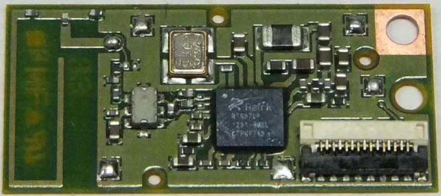
WY7-21
Feb 25, 2014Wireless LAN Module
Equipment Class
DTS - Digital Transmission System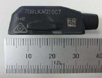
WY7-11
Dec 26, 2013Wireless Unit
Equipment Class
DXX - Part 15 Low Power Communication Device Transmitter