WZ7AR150WSAIS Receiver
Alltek Marine Electronics Corporation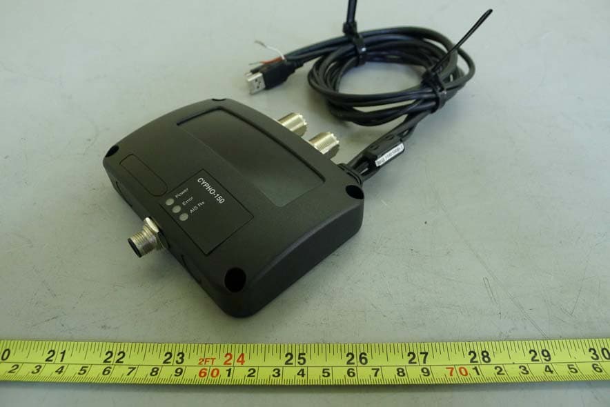
Click to zoom
Application Details
- Equipment Class
- DTS - Digital Transmission System
- Date of Grant
- May 12, 2013
- Application Purpose
- Original Equipment
- Date of Application
- May 09, 2013
- Equipment Note
- AIS Receiver
- Frequency Range
- 2412.00000000 - 2462.00000000
- Country
- Taiwan
Documents & Files
Document Text
Text extracted from the exhibit documents filed with the FCC. Open a document above to read the original.
Users Manual
User’s Manual CYPHO-150WS I Copyright The entire contents of this instruction manual, including any future contents updates, revisions, and specification modifications, shall remain the property of Alltek Marine Electronics Corp. (hereinafter called AMEC) at all times. Unauthorized copies or reproduces of this manual, either in part or as a whole, is prohibited. The contents herein can only be used for the purpose subjects to this manual. Disclaimer The contents of this manual are well prepared by AMEC. As we are constantly improving our products, AMEC shall incur no liability based on the contents, updates or modification of the contents, or the lack of contents in this manual. Contact us at: Technical Support: Sales & Marketing: ALLTEK MARINE ELECTRONICS CO., LTD 7F, NO. 605, Ruei-Guang RD., Neihu, Taipei, Taiwan 114 TEL: +886 2 2627 1599 FAX: +886 2 2627 1600 www.alltekmarine.com (Your Local Dealer/Agent Warranty Stamp) Version 1.00 II WARNING The equipment said in this manual must only be used to which it was designed. Improper operation or installation may cause damages to the equipment or personal injury. AMEC will not incur any liability of equipment damage or personal injury due to improper use or installation of the equipment. It is strongly recommended to read this manual and the following safety instructions before proceeding to installation or operation. SAFETY INSTRUCTIONS ELECTRICAL SHOCK HAZARD Do not disassemble equipment. Only qualified personnel could work inside the equipment. Improper disassemble or modification could cause electrical shocks, fire, or personal injury. WARNING WARNING TURN OFF THE POWER IMMEDIATELY IF WATER LEAKS INTO THE EQUIPMENT OR OBJECT DROPS INTO THE EQUIPMENT. Continue operating the equipment could cause electrical shock or fire. Contact your nearest distributor for service. TURN OFF THE POWER BEFORE PROCEEDING WITH INSTALLATION. Proceeding with installation with the power on could cause electrical shock or fire. EVEN THOUGH THE EQUIPMENT IS WATERPROOF, PLEASE AVOID DIRECT CONTACT WITH RAIN OR SPLASHING WATER. Electrical shock or fire could be resulted if water leaks into the equipment. AVOID OPERATING THE EQUIPMENT WITH WET HANDS. Electrical shocks could be resulted if operating with wet hands. PLEASE USE THE PROPER FUSE. Damage to the equipment or fire could be resulted if using the wrong fuse. Warning Label A warning label (Figure 2-1-1) is attached underneath the equipment. Warranty of the equipment will be invalid if this label is detached or broken. AMEC and your local agent/dealer will not bare any responsibility of any damage to the equipment, or damage in related to the equipment, personnel injury, and etc. Reject the equipment if this label is detached or broken. Please contact your local agent/dealer if this label is missing. WARNING Name: Warning Label No Warranty if this label is detached or broken. 保固撕毁无效 Warning 注意 MAKE SURE THE POWER SOURCE AND THE POWER INPUT OF THE EQUIPMENT ARE COMPATIBLE. Damage to the equipment and fire could be resulted if the power sources are not correct. Please check the correct power input on the adaptor. III FOREWORD ALLTEK MARINE ELECTRONICS (hereinafter called “AMEC”) thank you for choosing our CYPHO-150 Series Automatic Identification System Receiver. No matter where you sail, you can enjoy your voyage journey more having a better control on your surrounding sea with CYPHO-150 AIS receiver series onboard. The equipment you have purchased is designed with precision performance and quality. Each of AMEC’s equipment has been strictly tested to meet the rigorous demands of the marine environment. Unless improper use or false installation or maintenance, the equipment should function at its best. Thank you again for choosing AMEC product and wish you bon voyage! IV 1 INTRODUCTION .............................................................................................. 1 1.1 CYPHO-150X Series Overview ...................................................................................... 1 1.2 Comparison of CYPHO-150 models ............................................................................... 1 1.3 Type of AIS ..................................................................................................................... 2 1.4 AIS Message Type .......................................................................................................... 2 1.5 About This Manual .......................................................................................................... 3 1.6 Important Notice.............................................................................................................. 4 2 GETTING STARTED ........................................................................................ 5 2.1 Items in the Package ...................................................................................................... 5 2.2 Power ON / OFF ............................................................................................................. 5 2.3 CYPHO-150 LED Indicators ........................................................................................... 6 2.4 CYPHO-150WS LED Indicators ...................................................................................... 7 3 INSTALLATION ................................................................................................ 8 3.1 CYPHO-150 Connection Interface .................................................................................. 8 3.2 CYPHO-150 WS Connection Interface ........................................................................... 8 3.3 Installation Precautions ................................................................................................... 9 3.4 Mounting Instructions ...................................................................................................... 9 3.5 Wiring Instructions Applicable to all CYPHO 150 models. .................…
Text truncated - open the document above for the full version.
Cover Letter(s)
RV-1303021 Report No.: NEI-FCCP-1-1212216 Page 104 of 110 Neutron Engineering Inc. 10 RF EXPOSURE COMPLIANCE 10.1 LIMIT Systems operating under the provisions of this section shall be operated in a manner that ensures that the public is not exposed to radio frequency energy levels in excess limit for maximum permissible exposure. In accordance with 47 CFR FCC Part 2 Subpart J, section 2.1091 this device has been defined as a mobile device whereby a distance of 0.2 m normally can be maintained between the user and the device. (A) Limits for Occupational / Controlled Exposure Frequency Range (MHz) Electric Field Strength (E) (V/m) Magnetic Field Strength (H) (A/m) Power Density (S) (mW/ cm 2 ) Averaging Time |E| 2 ,|H| 2 or S (minutes) 0.3-3.0 614 1.63 (100)* 6 3.0-30 1842 / f 4.89 / f (900 / f)* 6 30-300 61.4 0.163 1.0 6 300-1500 F/300 6 1500-100,000 5 6 (B) Limits for General Population / Uncontrolled Exposure Frequency Range (MHz) Electric Field Strength (E) (V/m) Magnetic Field Strength (H) (A/m) Power Density (S) (mW/ cm 2 ) Averaging Time |E| 2 ,|H| 2 or S (minutes) 0.3-1.34 614 1.63 (100)* 30 1.34-30 824/f 2.19/f (180/f)* 30 30-300 27.5 0.073 0.2 30 300-1500 F/1500 30 1500-100,000 1.0 30 NOTE: f = frequency in MHz ; *Plane-wave equivalent power density. 10.2 MEASUREMENT INSTRUMENTS LIST Item Kind of EquipmentManufacturer Type No. Serial No. Calibrated until 1 Power Meter Anritsu ML2495A 1128008 Feb,20,2013 2 Power Meter Sensor Anritsu MA2411B 1126001 Feb,20,2013 10.3 MPE CALCULATION METHOD E (V/m) = d GP××30 Power Density: Pd (W/m²) = 377 2 E E = Electric field (V/m) P = Peak RF output power (W) G = EUT Antenna numeric gain (numeric) d = Separation distance between radiator and human body (m) The formula can be changed to Pd = 2 377 30 d GP × ×× From the peak EUT RF output power, the minimum mobile separation distance, d=0.2m, as well as the gain of the used antenna, the RF power density can be obtained RV-1303021 Report No.: NEI-FCCP-1-1212216 Page 105 of 110 Neutron Engineering Inc. 10.4 TEST SETUP LAYOUT 10.5 DEVIATION FROM TEST STANDARD No deviation 10.6 EUT OPERATING CONDITIONS The EUT tested system was configured as the statements of 4.6 Unless otherwise a special operating condition is specified in the follows during the testing. RV-1303021 Report No.: NEI-FCCP-1-1212216 Page 106 of 110 Neutron Engineering Inc. 10.7 TEST RESULTS - 2400-2483.5 MHZ E.U.T AIS Receiver Model Name CYPHO-150WS Temperature 26°C Relative Humidity 60% Test Voltage DC 12V Test Mode IEEE 802.11b/2412 MHz, 2437 MHz, 2462 MHz Frequency Antenna Gain (dBi) Antenna Gain (numeric) Peak Output Power (dBm) Peak Output Power (mW) Power Density (S) (mW/cm²) Limit of Power Density (S) (mW/cm²) Result 2412 MHz 2.00 1.5849 15.2400 33.4195 0.010543 1 PASS 2437 MHz 2.00 1.5849 15.0300 31.8420 0.010045 1 PASS 2462 MHz 2.00 1.5849 15.2500 33.4965 0.010567 1 PASS RV-1303021 Report No.: NEI-FCCP-1-1212216 Page 107 of 110 Neutron Engineering Inc. E.U.T AIS Receiver Model Name CYPHO-150WS Temperature 26°C Relative Humidity 60% Test Voltage DC 12V Test Mode IEEE 802.11g/2412 MHz, 2437 MHz, 2462 MHz Frequency Antenna Gain (dBi) Antenna Gain (numeric) Peak Output Power (dBm) Peak Output Power (mW) Power Density (S) (mW/cm²) Limit of Power Density (S) (mW/cm²) Result 2412 MHz 2.00 1.5849 19.7500 94.4061 0.029782 1 PASS 2437 MHz 2.00 1.5849 19.7600 94.6237 0.029850 1 PASS 2462 MHz 2.00 1.5849 19.1200 81.6582 0.025760 1 PASS RV-1303021 Report No.: NEI-FCCP-1-1212216 Page 108 of 110 Neutron Engineering Inc. E.U.T AIS Receiver Model Name CYPHO-150WS Temperature 26°C Relative Humidity 60% Test Voltage DC 12V Test Mode IEEE 802.11n (20 MHz)/2412 MHz, 2437 MHz, 2462 MHz Frequency Antenna Gain (dBi) Antenna Gain (numeric) Peak Output Power (dBm) Peak Output Power (mW) Power Density (S) (mW/cm²) Limit of Power Density (S) (mW/cm²) Result 2412 MHz 2.99 1.9907 24.9200 310.4560 0.123013 1 PASS 2437 MHz 2.99 1.9907 25.0800 322.1069 0.127629 1 PASS 2462 MHz 2.99 1.9907 24.0800 255.8586 0.101380 1 PASS
External Photos
RV-0000000 Project No.: 1212216 Page 2 of 12 Neutron Engineering Inc. 1212216 121221 6 RV-0000000 Project No.: 1212216 Page 3 of 12 Neutron Engineering Inc. 1212216 121221 6
ID Label/Location Info
File No.: Label of CYPHO-150WS family Version: 1.0 Issue Date: Jan. 31, 2013 Page: 5 of 5 FGM-002B 1. Label Figure 1 Label 2. Label position Figure 2 Label position
Internal Photos
RV-0000000 Project No.: 1212216 Page 4 of 12 Neutron Engineering Inc. 1212216 121221 6 RV-0000000 Project No.: 1212216 Page 5 of 12 Neutron Engineering Inc. 1212216 121221 6 RV-0000000 Project No.: 1212216 Page 6 of 12 Neutron Engineering Inc. 1212216 121221 6 RV-0000000 Project No.: 1212216 Page 7 of 12 Neutron Engineering Inc. 1212216 121221 6 RV-0000000 Project No.: 1212216 Page 8 of 12 Neutron Engineering Inc. 1212216 121221 6 RV-0000000 Project No.: 1212216 Page 9 of 12 Neutron Engineering Inc. 1212216 121221 6 RV-0000000 Project No.: 1212216 Page 10 of 12 Neutron Engineering Inc. 1212216 121221 6 RV-0000000 Project No.: 1212216 Page 11 of 1 2 Neutron Engineering Inc. 1212216 121221 6 RV-0000000 Project No.: 1212216 Page 12 of 12 Neutron Engineering Inc. 1212216
Test Report
RV-1303021 Report No.: NEI-FCCP-1-1212216 Page 1 of 110 Neutron Engineering Inc. Radio Test Report FCC ID: WZ7AR150WS This report concerns (check one) : Original Grant Class II Change Issued Date : Mar. 27, 2013 Project No. : 1212216 Equipment : AIS Receiver Model Name : CYPHO-150WS; AR-150WS Applicant : Alltek Marine Electronics Corporation Address : 7F, No.605, Ruei-Guang Rd., Neihu, Taipei, Taiwan, R.O.C. 114 Tested by: Neutron Engineering Inc. EMC Laboratory Date of Receipt: Dec. 28, 2012 Date of Test: Dec. 28, 2012 ~ Feb. 27, 2013 Testing Engineer : (Josh Lin) Technical Manager : (Jeff Yang) Authorized Signatory : (Andy Chiu) Neutron Engineering Inc. B1, No. 37, Lane 365, YangGuang St., NeiHu District 114, Taipei, Taiwan. TEL: +886-2-2657-3299 FAX: +886-2-2657-3331 RV-1303021 Report No.: NEI-FCCP-1-1212216 Page 2 of 110 Neutron Engineering Inc. Declaration Neutron represents to the client that testing is done in accordance with standard procedures as applicable and that test instruments used has been calibrated with the standards traceable to National Measurement Laboratory (NML) of R.O.C., or National Institute of Standards and Technology (NIST) of U.S.A. Neutron's reports apply only to the specific samples tested under conditions. It is manufacture’s responsibility to ensure that additional production units of this model are manufactured with the identical electrical and mechanical components. Neutron shall have no liability for any declarations, inferences or generalizations drawn by the client or others from Neutron issued reports. Neutron’s reports must not be used by the client to claim product endorsement by the authorities or any agency of the Government. This report is the confidential property of the client. As a mutual protection to the clients, the public and Neutron-self, extracts from the test report shall not be reproduced except in full with Neutron’s authorized written approval. Neutron’s laboratory quality assurance procedures are in compliance with the ISO Guide 17025 requirements, and accredited by the conformity assessment authorities listed in this test report. Limitation For the use of the authority's logo is limited unless the Test Standard(s)/Scope(s)/Item(s) mentioned in this test report is (are) included in the conformity assessment authorities acceptance respective. RV-1303021 Report No.: NEI-FCCP-1-1212216 Page 3 of 110 Neutron Engineering Inc. Table of Contents REPORT ISSUED HISTORY 5 1 CERTIFICATION 6 2 . SUMMARY OF TEST RESULTS 7 2.1 TEST FACILITY 8 2.2 MEASUREMENT UNCERTAINTY 8 3 GENERAL INFORMATION 9 3.1 GENERAL DESCRIPTION OF EUT 9 3.2 DESCRIPTION OF TEST MODES 11 3.3 TABLE OF PARAMETERS OF TEXT SOFTWARE SETTING 12 3.4 BLOCK DIAGRAM SHOWING THE CONFIGURATION OF SYSTEM TESTED 13 3.5 DESCRIPTION OF SUPPORT UNITS 14 4 ANTENNA CONDUCTED SPURIOUS EMISSION 15 4.1 LIMIT 15 4.2 MEASUREMENT INSTRUMENTS LIST 15 4.3 TEST PROCEDURES 15 4.4 TEST SETUP LAYOUT 15 4.5 DEVIATION FROM TEST STANDARD 15 4.6 EUT OPERATING CONDITIONS 15 4.7 TEST RESULTS - 2400-2483.5 MHZ 16 5 6 DB BANDWIDTH 28 5.1 LIMIT 28 5.2 MEASUREMENT INSTRUMENTS LIST 28 5.3 TEST PROCEDURES 28 5.4 TEST SETUP LAYOUT 28 5.5 DEVIATION FROM TEST STANDARD 28 5.6 EUT OPERATING CONDITIONS 28 5.7 TEST RESULTS - 2400-2483.5 MHZ 29 6 MAXIMUM PEAK CONDUCTED OUTPUT POWER 35 6.1 LIMIT 35 6.2 MEASUREMENT INSTRUMENTS LIST 35 6.3 TEST PROCEDURES 35 6.4 TEST SETUP LAYOUT 35 6.5 DEVIATION FROM TEST STANDARD 35 6.6 EUT OPERATING CONDITIONS 35 6.7 TEST RESULTS - 2400-2483.5 MHZ 36 7 RADIATED SPURIOUS EMISSION (9 KHZ TO 1 GHZ) 39 7.1 LIMIT 39 7.2 MEASUREMENT INSTRUMENTS LIST 40 RV-1303021 Report No.: NEI-FCCP-1-1212216 Page 4 of 110 Neutron Engineering Inc. Table of Contents 7.3 MEASURING INSTRUMENTS SETTING 40 7.4 TEST PROCEDURES 41 7.5 DEVIATION FROM TEST STANDARD 41 7.6 TEST SETUP LAYOUT 41 7.7 EUT OPERATING CONDITIONS 42 7.8 TEST RESULTS - 2400-2483.5 MHZ 43 8 RADIATED SPURIOUS EMISSION (ABOVE 1 GHZ) 45 8.1 LIMIT 45 8.2 MEASUREMENT INSTRUMENTS LIST 46 8.3 MEASURING INSTRUMENTS SETTING 46 8.4 TEST PROCEDURES 47 8.5 DEVIATION FROM TEST STANDARD 47 8.6 TEST SETUP LAYOUT 47 8.7 EUT OPERATING CONDITIONS 48 8.8 TEST RESULTS - 2400-2483.5 MHZ 49 8.9 TEST RESULTS (RESTRICTED BANDS) 85 9 POWER SPECTRAL DENSITY 97 9.1 LIMIT 97 9.2 MEASUREMENT INSTRUMENTS LIST 97 9.3 TEST PROCEDURES 97 9.4 TEST SETUP LAYOUT 97 9.5 DEVIATION FROM TEST STANDARD 97 9.6 EUT OPERATING CONDITIONS 97 9.7 TEST RESULTS - 2400-2483.5 MHZ 98 10 RF EXPOSURE COMPLIANCE 104 10.1 LIMIT 104 10.2 MEASUREMENT INSTRUMENTS LIST 104 10.3 MPE CALCULATION METHOD 104 10.4 TEST SETUP LAYOUT 105 10.5 DEVIATION FROM TEST STANDARD 105 10.6 EUT OPERATING CONDITIONS 105 10.7 TEST RESULTS - 2400-2483.5 MHZ 106 11 EUT TEST PHOTO 109 RV-1303021 Report No.: NEI-FCCP-1-1212216 Page 5 of 110 Neutron Engineering Inc. REPORT ISSUED HISTORY Revised Version No. Description Issued Date - Initial Issue. Mar. 08, 2013 RV-1303021 A. Revised model name(s). B. Revised test description. Mar. 27, 2013 RV-1303021 Report No.: NEI-FCCP-1-1212216 Page 6 of 110 Neutron Engineering Inc. 1 CERTIFICATION Equipment : AIS Receiver Brand Name : AMEC Model Name : CYPHO-150WS; AR-150WS A p p l i c a n t : Alltek Marine Electronics Corporation Date of Test : Dec. 28, 2012 ~ Feb. 27, 2013 Standards : FCC Part 15, Subpart C: 2011 ANSI C63.4: 2009 The above equipment has been tested and found compliance with the requirement of the relative standards by Neutron Engineering Inc. EMC Laboratory. The test data, data evaluation, and equipment configuration contained in our test report (Ref No. NEI-FCCP-1-1212216) were obtained utilizing the test procedures, test instruments, test sites that has been accredited by the Authority of NVLAP and TAF according to the ISO-17025 quality assessment standard and technical standard(s). RV-1303021 Report No.: NEI-FCCP-1-1212216 Page 7 of 110 Neutron Engineering Inc. 2. SUMMARY OF TEST RESULTS FCC Part 15, Subpart C: 2011 Standard Clause Test Item Result FCC Part 15, Subpart …
Text truncated - open the document above for the full version.
Test Setup Photos
RV-1303021 Report No.: NEI-FCCP-1-1212216 Page 109 of 110 Neutron Engineering Inc. 11 EUT TEST PHOTO Radiated spurious emission test photos 1212216 1212216 RV-1303021 Report No.: NEI-FCCP-1-1212216 Page 110 of 110 Neutron Engineering Inc. Radiated spurious emission test photos 1212216
Contact Information
Applicant
Leo Hsieh(QC Specialist)
Non-Technical Contact
Neutron Engineering IncKate Lin
[email protected]886-2-2657-3299
Test Firm
BTL Inc.Andy Yeh
Technical Specifications
| # | Rule Parts | Frequency Range | Power Output |
|---|---|---|---|
| 1 | 15C | 2.41 GHz - 2.46 GHz | 94.60 mW |
Other Applications from Alltek Marine Electronics Corporation
WZ7ATON-N321-N323
Jun 30, 2023AIS AtoN (Aids to Navigation)
Equipment Class
AIS - Automatic Identification Systems
WZ7AIS-P200CS
Dec 20, 2020AIS Class B CSTDMA Transponder with Chartplotter
Equipment Class
AIS - Automatic Identification Systems
WZ7AIS-P200SO
Dec 20, 2020AIS Class B SOTDMA Transponder with Chartplotter
Equipment Class
AIS - Automatic Identification Systems
WZ7AIS-W
Feb 13, 2014AIS Class B Transponder
Equipment Class
AIS - Automatic Identification Systems
WZ7AIS-B108
Feb 12, 2014AIS Class B Transponder
Equipment Class
AIS - Automatic Identification Systems