WZ7CAMINO-201Class B AIS Transponder
Alltek Marine Electronics Corporation
Click to zoom
Application Details
- Equipment Class
- AIS - Automatic Identification Systems
- Date of Grant
- Apr 04, 2011
- Application Purpose
- Original Equipment
- Date of Application
- Mar 01, 2011
- Equipment Note
- Class B AIS Transponder
- Frequency Range
- 156.52500000 - 156.52500000
- Country
- Taiwan
Documents & Files
Document Text
Text extracted from the exhibit documents filed with the FCC. Open a document above to read the original.
Users Manual
I II Copyright The entire contents of this instruction manual, including any future updates, revisions, and modifications, shall remain the property of AMEC at all times. Unauthorized copies or reproduction of this manual, either in part or whole, in any form of print and electronic media, is prohibited. The contents herein can only be used for the intended purpose of this manual. Disclaimer AMEC is devoted to publish and maintain this product manual. As we continue to improve our AIS products to satisfy all customers‟ needs, information in this document is subject to change without notice. AMEC does not make any representations or warranties (implied or otherwise) regarding the accuracy and completeness of this document and shall in no event be liable for any loss of profit or any commercial damage, including but not limited to special, incidental, consequential, or other damage. Contact us at: Technical Support: Sales & Marketing: ALLTEK MARINE ELECTRONICS CO., LTD 7F, No.605, Ruei-Guang Road, Neihu, Taipei, Taiwan 114 TEL: +886 2 2627 1599 FAX: +886 2 2627 1600 www.alltekmarine.com (Your Local Dealer/Agent Warranty Stamp) Version 1.52 III FOR USERS IN THE UNITED STATES OF AMERICA ONLY WARNING: It is a violation of the rules of the Federal Communications Commission to input an MMSI that has not been properly assigned to the end user, or to otherwise input any inaccurate data in this device. ★ The entry of static data into this device shall be performed by the vendor of the device or by an appropriately qualified person in the business of installing marine communications equipment on board vessels. ★ Instructions on how to accurately enter and confirm static data in the device can be found in Section 5.3 of this user manual. The equipment said in this manual must only be used to which it was designed. Improper operation or installation may cause damage to the equipment or injury to personnel. AMEC will not incur any liability of equipment damage or personal injury due to improper use or installation of the equipment. It is strongly recommended to read this manual and the following safety instructions before proceeding to installation or operation. WARNING! SAFETY INSTRUCTIONS ELECTRICAL SHOCK HAZARD. Do not open the case of the equipment. Only qualified personnel could work on the interior of the equipment. WARNING WARNING TURN OFF THE POWER IMMEDIATELY IF WATER LEAKS INTO THE EQUIPMENT OR OBJECT DROPS INTO THE EQUIPMENT. Continue operating the equipment could cause electrical shock or fire. Contact your nearest distributor for service. DO NOT DISASSEMBLE OR MODIFY THE EQUIPMENT. Improper disassemble or modification could cause electrical shocks, fire, or personal injury. DO NOT PLACE ANY LIQUID-FILLED CONTAINER ON TOP OF THE EQUIPMENT. Electrical shocks could be resulted if the device is contaminated with liquid. TURN OFF THE POWER IMMEDIATELY IF THE EQUIPMENT IS EMMITTING SMOKE OR FIRE. Continue operating the equipment could cause electrical shock or fire. Contact your nearest distributor for service. EVEN THOUGH THE EQUIPMENT IS WATERPROOF, AVOID DIRECT CONTACT WITH RAIN OR SPLASHING WATER. Electrical shock or fire could be resulted if water leaks into the equipment. AVOID OPERATING THE EQUIPMENT WITH WET HANDS. Electrical shocks could be resulted if operating with wet hands. IV FORWARD Congratulations on the purchase of your new CAMINO-201 Automatic Identification System (hereinafter called “AIS”). No matter where you sail now, you can have a better control of your surrounding sea, and have an enjoyable voyage. Camino-201 AIS is strictly tested to meet the rigorous demands of the marine environment. Unless improper use, installation, or maintenance, the equipment should function properly at its optimum. We thank you for choosing our product and we wish you a bon voyage. V Table of Contents I. COPY RIGHT & DISCLAIMER II. WARNING & SAFETY INSTRUCTION III. FORWARD Pages 1 INTRODUCTION ............................................................................................ 1 1.1 CAMINO-201 Overview ................................................................................................ 1 1.2 Type of AIS ................................................................................................................... 2 1.3 AIS Message Type ........................................................................................................ 3 1.4 AIS Report Rate ............................................................................................................ 3 1.5 About This Manual ....................................................................................................... 4 1.6 Important Notice .......................................................................................................... 4 2 INSTALLATION ............................................................................................. 5 2.1 General ......................................................................................................................... 5 2.1.1 Safety Instructions ........................................................................................................ 5 2.1.2 Unpacking and Handling the Unit.............................................................................. 6 2.1.3 Items in the Package ..................................................................................................... 6 2.2 Installation Procedure ................................................................................................. 7 2.2.1 Installation Precautions ............................................................................................... 7 2.2.2 Step by Step Installation Instructions ...................................................................... 8 2.2.3 Connector Pin Definition and Wiring ...................................................................... 13 2.2.4 VHF Antenna Installation .....................…
Text truncated - open the document above for the full version.
External Photos
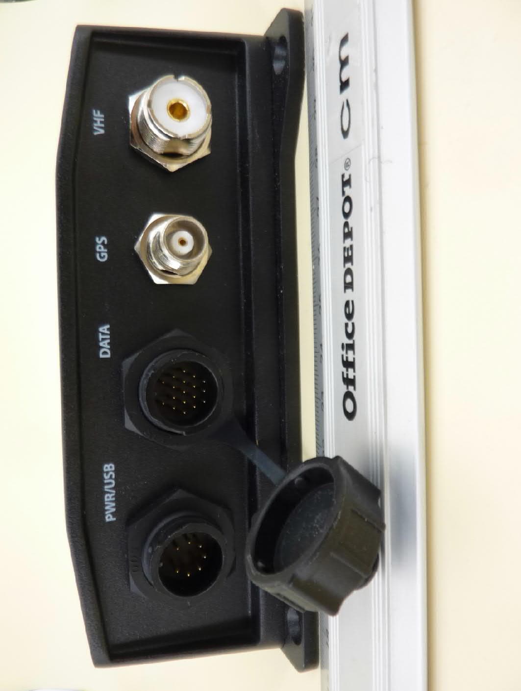
Alltek Marine Electronics Corp. ◆ 7F, No.605, Ruei-Guang Rd., Neihu, Taipei, Taiwan, 11492 ◆ www.alltekmarine.com FCC ID: WZ7CAMINO-201 External Photos of CAMINO-201 Figure 1: Front View of CAMINO-201 Alltek Marine Electronics Corp. ◆ 7F, No.605, Ruei-Guang Rd., Neihu, Taipei, Taiwan, 11492 ◆ www.alltekmarine.com Figure 2: Rear View of CAMINO-201 Alltek Marine Electronics Corp. ◆ 7F, No.605, Ruei-Guang Rd., Neihu, Taipei, Taiwan, 11492 ◆ www.alltekmarine.com Figure 3: Side View of CAMINO-201
ID Label/Location Info
Alltek Marine Electronics Corp. ◆ 7F, No.605, Ruei-Guang Rd., Neihu, Taipei, Taiwan, 11492 ◆ www.alltekmarine.com FCC ID: WZ7CAMINO-201 Type Label and Warning Label Figure 1: Type Label with FCC ID Figure 2: Warning Label Figure 3: Label Location (rear panel of the unit) Alltek Marine Electronics Corp. ◆ 7F, No.605, Ruei-Guang Rd., Neihu, Taipei, Taiwan, 11492 ◆ www.alltekmarine.com Figure 4: Type Label Artwork 38 mm 29 mm Power Supply: 12 / 24V DC Compass Safe Distance: 1.2M FCC ID: WZ7CAMINO-201 USCG Approval No.: 165.156/13/0 Serial Number: 0700 Maker: Alltek Marine Electronics Corp Made in Taiwan CAMINO-201 Class B AIS
ID Label/Location Info
Alltek Marine Electronics Corp. ◆ 7F, No.605, Ruei-Guang Rd., Neihu, Taipei, Taiwan, 11492 ◆ www.alltekmarine.com FCC ID: WZ7CAMINO-201 Warning Label Figure 1: Warning Label Figure 2: Label Location (rear panel of the unit) Alltek Marine Electronics Corp. ◆ 7F, No.605, Ruei-Guang Rd., Neihu, Taipei, Taiwan, 11492 ◆ www.alltekmarine.com Figure 3: Label Location #2 (rear panel of the unit)
Internal Photos
Alltek Marine Electronics Corp. ◆ 7F, No.605, Ruei-Guang Rd., Neihu, Taipei, Taiwan, 11492 ◆ www.alltekmarine.com FCC ID: WZ7CAMINO-201 Internal Photos of CAMINO-201 Figure 1: Top View of Internal CAMINO-201 Figure 2: Internal View with Back Cover removed Alltek Marine Electronics Corp. ◆ 7F, No.605, Ruei-Guang Rd., Neihu, Taipei, Taiwan, 11492 ◆ www.alltekmarine.com Figure 3: Internal View with CPU / RF Module removed Figure 4: Top View of CPU / RF Module with Shielding Case Alltek Marine Electronics Corp. ◆ 7F, No.605, Ruei-Guang Rd., Neihu, Taipei, Taiwan, 11492 ◆ www.alltekmarine.com Figure 5: Top View of CPU / RF Module with Upper Shielding Case removed Alltek Marine Electronics Corp. ◆ 7F, No.605, Ruei-Guang Rd., Neihu, Taipei, Taiwan, 11492 ◆ www.alltekmarine.com Figure 6: Top View of CPU Module Figure 7: Bottom View of CPU Module Alltek Marine Electronics Corp. ◆ 7F, No.605, Ruei-Guang Rd., Neihu, Taipei, Taiwan, 11492 ◆ www.alltekmarine.com Figure 8: Top View of RF Module Figure 9: Bottom View of RF Module
Operational Description
I II Copyright The entire contents of this instruction manual, including any future updates, revisions, and modifications, shall remain the property of AMEC at all times. Unauthorized copies or reproduction of this manual, either in part or whole, in any form of print and electronic media, is prohibited. The contents herein can only be used for the intended purpose of this manual. Disclaimer AMEC is devoted to publish and maintain this product manual. As we continue to improve our AIS products to satisfy all customers‟ needs, information in this document is subject to change without notice. AMEC does not make any representations or warranties (implied or otherwise) regarding the accuracy and completeness of this document and shall in no event be liable for any loss of profit or any commercial damage, including but not limited to special, incidental, consequential, or other damage. Contact us at: Technical Support: Sales & Marketing: ALLTEK MARINE ELECTRONICS CO., LTD 7F, No.605, Ruei-Guang Road, Neihu, Taipei, Taiwan 114 TEL: +886 2 2627 1599 FAX: +886 2 2627 1600 www.alltekmarine.com (Your Local Dealer/Agent Warranty Stamp) Version 1.52 III FOR USERS IN THE UNITED STATES OF AMERICA ONLY WARNING: It is a violation of the rules of the Federal Communications Commission to input an MMSI that has not been properly assigned to the end user, or to otherwise input any inaccurate data in this device. ★ The entry of static data into this device shall be performed by the vendor of the device or by an appropriately qualified person in the business of installing marine communications equipment on board vessels. ★ Instructions on how to accurately enter and confirm static data in the device can be found in Section 5.3 of this user manual. The equipment said in this manual must only be used to which it was designed. Improper operation or installation may cause damage to the equipment or injury to personnel. AMEC will not incur any liability of equipment damage or personal injury due to improper use or installation of the equipment. It is strongly recommended to read this manual and the following safety instructions before proceeding to installation or operation. WARNING! SAFETY INSTRUCTIONS ELECTRICAL SHOCK HAZARD. Do not open the case of the equipment. Only qualified personnel could work on the interior of the equipment. WARNING WARNING TURN OFF THE POWER IMMEDIATELY IF WATER LEAKS INTO THE EQUIPMENT OR OBJECT DROPS INTO THE EQUIPMENT. Continue operating the equipment could cause electrical shock or fire. Contact your nearest distributor for service. DO NOT DISASSEMBLE OR MODIFY THE EQUIPMENT. Improper disassemble or modification could cause electrical shocks, fire, or personal injury. DO NOT PLACE ANY LIQUID-FILLED CONTAINER ON TOP OF THE EQUIPMENT. Electrical shocks could be resulted if the device is contaminated with liquid. TURN OFF THE POWER IMMEDIATELY IF THE EQUIPMENT IS EMMITTING SMOKE OR FIRE. Continue operating the equipment could cause electrical shock or fire. Contact your nearest distributor for service. EVEN THOUGH THE EQUIPMENT IS WATERPROOF, AVOID DIRECT CONTACT WITH RAIN OR SPLASHING WATER. Electrical shock or fire could be resulted if water leaks into the equipment. AVOID OPERATING THE EQUIPMENT WITH WET HANDS. Electrical shocks could be resulted if operating with wet hands. IV FORWARD Congratulations on the purchase of your new CAMINO-201 Automatic Identification System (hereinafter called “AIS”). No matter where you sail now, you can have a better control of your surrounding sea, and have an enjoyable voyage. Camino-201 AIS is strictly tested to meet the rigorous demands of the marine environment. Unless improper use, installation, or maintenance, the equipment should function properly at its optimum. We thank you for choosing our product and we wish you a bon voyage. V Table of Contents I. COPY RIGHT & DISCLAIMER II. WARNING & SAFETY INSTRUCTION III. FORWARD Pages 1 INTRODUCTION ............................................................................................ 1 1.1 CAMINO-201 Overview ................................................................................................ 1 1.2 Type of AIS ................................................................................................................... 2 1.3 AIS Message Type ........................................................................................................ 3 1.4 AIS Report Rate ............................................................................................................ 3 1.5 About This Manual ....................................................................................................... 4 1.6 Important Notice .......................................................................................................... 4 2 INSTALLATION ............................................................................................. 5 2.1 General ......................................................................................................................... 5 2.1.1 Safety Instructions ........................................................................................................ 5 2.1.2 Unpacking and Handling the Unit.............................................................................. 6 2.1.3 Items in the Package ..................................................................................................... 6 2.2 Installation Procedure ................................................................................................. 7 2.2.1 Installation Precautions ............................................................................................... 7 2.2.2 Step by Step Installation Instructions ...................................................................... 8 2.2.3 Connector Pin Definition and Wiring ...................................................................... 13 2.2.4 VHF Antenna Installation .....................…
Text truncated - open the document above for the full version.
Test Report
Report No. 105024R-RFCEP03V01 Page: 1 of 44 Test Report Product Name CAMINO-201 Class B AIS Transponder Model No. CAMINO-201 Applicant Alltek Marine Electronics Corp. Address 7F, No.605, Ruei Guang Rd., Neihu, Taipei, Taiwan, 114 R.O.C. Date of Receipt Apr. 27, 2010 Issued Date Sep. 24, 2010 Report No. 105024R-RFCEP03V01 Report Version V1.0 The Test Results relate only to the samples tested. The test report shall not be reproduced except in full without the written approval of QuieTek Corporation. Report No. 105024R-RFCEP03V01 Page: 2 of 44 Test Report Certification Issued Date: Sep. 24, 2010 Report No.: 105024R-RFCEP03V01 Product Name CAMINO-201 Class B AIS Transponder Applicant Alltek Marine Electronics Corp. Address 7F, No.605, Ruei Guang Rd., Neihu, Taipei, Taiwan, 114 R.O.C. Manufacturer Alltek Marine Electronics Corp. Model No. CAMINO-201 EUT Rated Voltage DC 12-28V EUT Test Voltage DC 12V and DC 24V Trade Name AMEC Applicable Standard ETSI EN 301 843-1:V1.2.1 (2004.06) ETSI EN 301 843-2:V1.2.1 (2004.06) Test Result Complied The test results relate only to the samples tested. The test report shall not be reproduced except in full without the written approval of QuieTek Corporation. Documented By : (Senior Adm. Specialist / Leven Huang ) Tested By : ( Engineer / Joe Guo ) Approved By : ( Manager / Vincent Lin ) Accredited by DNV, Nemko and NIST (NVLAP) Report No. 105024R-RFCEP03V01 Page: 3 of 44 TABLE OF CONTENTS Description Page 1. GENERAL INFORMATION .....................................................................................................5 1.1. EUT Description............................................................................................................................5 1.2. Tested System Details....................................................................................................................6 1.3. Configuration of tested System .....................................................................................................6 1.4. EUT Exercise Software .................................................................................................................6 1.5. Test Facility ...................................................................................................................................7 2. Conducted Emission....................................................................................................................8 2.1. Test Equipmen ...............................................................................................................................8 2.2. Test Setup ......................................................................................................................................8 2.3. Limits ............................................................................................................................................9 2.4. Test Procedure ...............................................................................................................................9 2.5. Test Specification ........................................................................................................................10 2.6. Uncertainty ..................................................................................................................................10 2.7. Test Result ...................................................................................................................................10 3. Radiated Emission ..................................................................................................................... 11 3.1. Test Equipment............................................................................................................................11 3.2. Test Setup ....................................................................................................................................11 3.3. Limits ..........................................................................................................................................12 3.4. Test Procedure .............................................................................................................................12 3.5. Test Specification ........................................................................................................................13 3.6. Uncertainty ..................................................................................................................................13 3.7. Test Result ...................................................................................................................................13 4. Electrostatic Discharge (ESD) ..................................................................................................14 4.1. Test Equipment............................................................................................................................14 4.2. Test Setup ....................................................................................................................................14 4.3. Test Level ....................................................................................................................................14 4.4. Test Procedure .............................................................................................................................15 4.5. Test Specification ........................................................................................................................15 4.6. Uncertainty ..................................................................................................................................15 4.7. Test Result ...................................................................................................................................15 5. Radiated Susceptibility (RS).....................................................................................................16 5…
Text truncated - open the document above for the full version.
Test Report
Report No.: 105024R-RFCEP03V01 Page : 1 of 7 Attachment 1: EUT Test Setup Photographs Front View of Conducted Test Back View of Conducted Test Report No.: 105024R-RFCEP03V01 Page : 2 of 7 Front View of Radiated Test (Loop) Back View of Radiated Test (Loop) Report No.: 105024R-RFCEP03V01 Page : 3 of 7 Front View of Radiated Test (Bilog) Back View of Radiated Test (Bilog) Report No.: 105024R-RFCEP03V01 Page : 4 of 7 Front View of Radiated Test (Horn) ESD Test Setup Report No.: 105024R-RFCEP03V01 Page : 5 of 7 Radiated Susceptibility Test Setup EFT/B Test Setup Report No.: 105024R-RFCEP03V01 Page : 6 of 7 EFT/B Test Setup-Clamp Conducted Susceptibility Test Setup Report No.: 105024R-RFCEP03V01 Page : 7 of 7 Conducted Susceptibility Test Setup-Clamp
Test Report
Report No.: 105024R-RFCEP03V01 Page : 1 of 15 Version:1.0 Attachment 2 : EUT Detailed Photographs (1) EUT Photo (2) EUT Photo Report No.: 105024R-RFCEP03V01 Page : 2 of 15 Version:1.0 (3) EUT Photo (4) EUT Photo Report No.: 105024R-RFCEP03V01 Page : 3 of 15 Version:1.0 (5) EUT Photo (6) EUT Photo Report No.: 105024R-RFCEP03V01 Page : 4 of 15 Version:1.0 (7) EUT Photo (8) EUT Photo Report No.: 105024R-RFCEP03V01 Page : 5 of 15 Version:1.0 (9) EUT Photo (10) EUT Photo
Test Report
Report No.: 105024R-RFCEP03V01 Page : 6 of 15 Version:1.0 (11) EUT Photo (12) EUT Photo Report No.: 105024R-RFCEP03V01 Page : 7 of 15 Version:1.0 (13) EUT Photo (14) EUT Photo Report No.: 105024R-RFCEP03V01 Page : 8 of 15 Version:1.0 (15) EUT Photo (16) EUT Photo Report No.: 105024R-RFCEP03V01 Page : 9 of 15 Version:1.0 (17) EUT Photo (18) EUT Photo Report No.: 105024R-RFCEP03V01 Page : 10 of 15 Version:1.0 (19) EUT Photo (20) EUT Photo Report No.: 105024R-RFCEP03V01 Page : 11 of 15 Version:1.0 (21) EUT Photo (22) EUT Photo Report No.: 105024R-RFCEP03V01 Page : 12 of 15 Version:1.0 (23) EUT Photo (24) EUT Photo Report No.: 105024R-RFCEP03V01 Page : 13 of 15 Version:1.0 (25) EUT Photo (26) EUT Photo Report No.: 105024R-RFCEP03V01 Page : 14 of 15 Version:1.0 (27) EUT Photo (28) EUT Photo Report No.: 105024R-RFCEP03V01 Page : 15 of 15 Version:1.0 (29) EUT Photo
Test Report
Bundesamt für Seeschifffahrt und Hydrographie Federal Maritime and Hydrographic Agency Test Report No.. BSH/46162/4321297/10-1Date: 07.06.2010page 2 of 112 Bundesamt für Seeschifffahrt und Hydrographie Federal Maritime and Hydrographic Agency Test Report No.. BSH/46162/4321297/10-1Date: 07.06.2010page 3 of 112 General Applicant:Alltek Marine Electronics Corp. 9F-1, No.360, Ruei Guang Rd., Neihu, Taipei, Taiwan, R.O.C. Equipment under test: Type:Camino 101 Manufacturer: Alltek Marine Electronics Corp. 9F-1, No.360, Ruei Guang Rd., Neihu, Taipei, Taiwan, R.O.C. Place of test:BSH test laboratory Hamburg, Room 916 Start of test:19 October 2009 End of test:27 May 2010 Test standards 1 : IEC 62287-1 Maritime navigation and radiocommunication equipment and systems- Automatic Identification Systems Class B shipborne equipment of the Universal Automatic Identification System (AIS) using CSTMA techniques Summary Test No. ReferenceSectionResult (passed/ not passed / not applicable / not tested) 2 IEC 62287-1 10 Operational testsPassed 3 IEC 62287-1 11 Physical testsNot included 4 IEC 62287-1 12 Specific tests of link layerPassed 5 IEC 62287-1 13 Specific tests of network layerPassed 6 IEC 62287-1 C.3 DSC functionality testsPassed 1 Numbers listed in the titles of the test sections of this report refer to the respective sections of IEC 61993-2 if not stated otherwise. Bundesamt für Seeschifffahrt und Hydrographie Federal Maritime and Hydrographic Agency Test Report No.. BSH/46162/4321297/10-1Date: 07.06.2010page 4 of 112 GENERAL......................................................................................................................................................................3 SUMMARY ....................................................................................................................................................................3 1GENERAL INFORMATION ............................................................................................................................7 1.1EQUIPMENT HISTORY.........................................................................................................................................7 1.1.1EUT system no 1......................................................................................................................................7 1.1.2EUT system no 2......................................................................................................................................8 1.1.3EUT system no 3......................................................................................................................................8 1.1.4EUT system no 4......................................................................................................................................9 1.1.5EUT system no 5......................................................................................................................................9 1.2T EST ENVIRONMENT........................................................................................................................................10 1.2.1Test environment no 1 ...........................................................................................................................10 1.3COMPOSITION..................................................................................................................................................11 1.4L EGEND............................................................................................................................................................12 1.5TEST NOTES......................................................................................................................................................12 1.5.1General problems..................................................................................................................................13 24. GENERAL REQUIREMENTS ..................................................................................................................14 2.14.2 M ANUALS.................................................................................................................................................14 2.24.3 MARKING AND IDENTIFICATION..............................................................................................................15 310 OPERATIONAL TESTS ..........................................................................................................................17 3.110.2 MODES OF OPERATING...........................................................................................................................17 3.1.110.2.1 Autonomous mode ....................................................................................................................17 3.1.1.110.2.1.1 Transmit Position reports................................................................................................................... 17 3.1.1.210.2.1.2 Receive Class A position reports .......................................................................................................18 3.1.1.310.2.1.3 Receive Class B”CS” position reports................................................................................................ 19 3.1.1.410.2.1.4 Receive in adjacent time periods .......................................................................................................20 3.1.1.510.2.1.5 Rx performance test ........................................................................................................................... 22 3.1.210.2.2 Assigned mode.........................................................................................................................23 3.1.2.110.2.2.1 Group assignment .............................................................................................................................. 23 3.1.2.210.2.2.2 Base station reservations...............................…
Text truncated - open the document above for the full version.
Test Report
Königswinkel 10 32825 Blomberg Germany Phone+49 5235 9500 0 Fax+49 5235 9500 10 TEST REPORT on IEC 62287-1: Edition 1.0(2006-03) MaritimeNavigation and RadiocommunicationEquipment andSystems: Class Bshipborne equipment of the Automatic Identification System(AIS) Part 1: Carrier sense division multiple access (CSTDMA) techniques Test Report Reference: F092025E3 Equipment under Test: AMEC Camino-101 Class B AIS Serial Number:- Applicant:AlltekMarine Electronics Corp. Manufacturer:Alltek Marine Electronics Corp. TEST REPORT REFERENCE: F092025E3 Examiner: Raimund BLASKDate of issue: 11 February 2010page2 of50 1 IDENTIFICATION.....................................................................................................................................3 1.1 APPLICANT.....................................................................................................................................3 1.2 MANUFACTURER..........................................................................................................................3 1.3 DATES.............................................................................................................................................3 1.4 TEST LABORATORY......................................................................................................................4 1.5 RESERVATION.…
Text truncated - open the document above for the full version.
Contact Information
Applicant
Leo Hsieh(QC Specialist)
Test Firm
PHOENIX TESTLAB GmbHHolger Bentje
Technical Specifications
| # | Rule Parts | Frequency Range | Power Output | Emission | Tolerance |
|---|---|---|---|---|---|
| 2 | 8 | 156.525 MHz - 156.525 MHz | 2 W | 14K2G2B | 3 ppm |
Other Applications from Alltek Marine Electronics Corporation
WZ7ATON-N321-N323
Jun 30, 2023AIS AtoN (Aids to Navigation)
Equipment Class
AIS - Automatic Identification Systems
WZ7AIS-P200CS
Dec 20, 2020AIS Class B CSTDMA Transponder with Chartplotter
Equipment Class
AIS - Automatic Identification Systems
WZ7AIS-P200SO
Dec 20, 2020AIS Class B SOTDMA Transponder with Chartplotter
Equipment Class
AIS - Automatic Identification Systems
WZ7AIS-W
Feb 13, 2014AIS Class B Transponder
Equipment Class
AIS - Automatic Identification Systems
WZ7AIS-B108
Feb 12, 2014AIS Class B Transponder
Equipment Class
AIS - Automatic Identification Systems