X280050Evoke Flow Spread Spectrum Transmitters
Imagination Technologies Ltd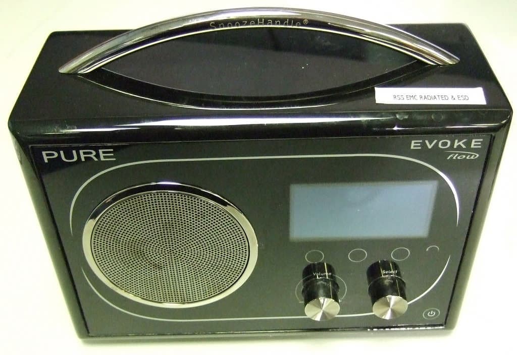
Click to zoom
Application Details
- Equipment Class
- DTS - Digital Transmission System
- Date of Grant
- Aug 26, 2010
- Application Purpose
- Original Equipment
- Date of Application
- Aug 23, 2010
- Equipment Note
- Evoke Flow Spread Spectrum Transmitters
- Frequency Range
- 2412.00000000 - 2462.00000000
- Company
- Imagination Technologies Ltd
- Country
- United Kingdom
Documents & Files
Document Text
Text extracted from the exhibit documents filed with the FCC. Open a document above to read the original.
Users Manual
Owner’s Manual Version 1.0 Warranty information Imagination Technologies Ltd. warrants to the end user that this product will be free from defects in materials and workmanship in the course of normal use for a period of two years from the date of purchase. This guarantee covers breakdowns due to manufacturing or design faults; it does not apply in cases such as accidental damage, however caused, wear and tear, negligence, adjustment, modification or repair not authorised by us. Please visit www.pure.com/register to register your product with us. Should you have a problem with your unit please contact your supplier or contact PURE Support at the address shown on the rear of this manual. If you need to return your product please use the original packaging and include all parts and accessories. We reserve the right to refuse incomplete or badly packaged returns. Disclaimer Imagination Technologies Limited makes no representation or warranties with respect to the content of this document and specifically disclaims any implied warranties of merchantability or fitness for any particular purpose. Further, Imagination Technologies Limited reserves the right to revise this publication and to make changes in it from time to time without obligation of Imagination Technologies Limited to notify any person or organization of such revisions or changes. Acknowledgement of License Agreements Portions of the code used in EVOKE Flow are subject to the following GPL and LPGL licenses and copyright: GNU General Public License Version 2 (GPLv2). For the full text of the license agreement go to: http://www.gnu.org/licenses/gpl-2.0.txt GNU Lesser General Public License Version 2.1 (LGPLv2.1). For the full text of the license agreement go to: http://www.gnu.org/licenses/lgpl-2.1.txt Copyright Copyright 2010 by Imagination Technologies Limited. All rights reserved. No part of this publication may be copied or distributed, transmitted, transcribed, stored in a retrieval system, or translated into any human or computer language, in any form or by any means, electronic, mechanical, magnetic, manual or otherwise, or disclosed to third parties without the express written permission of Imagination Technologies Limited. Portions Copyright ©2004 Intel Corporation. Trademarks EVOKE Flow, the EVOKE Flow logo, PURE, the PURE logo, Imagination Technologies, and the Imagination Technologies logo are trademarks or registered trademarks of Imagination Technologies Limited. The Wi-Fi CERTIFIED Logo is a certification mark of the Wi-Fi Alliance. All other product names are trademarks of their respective companies. Version 1 February 2010. IMPORTANT SAFETY INSTRUCTIONS 1. Read these instructions – All the safety and operating instructions should be read before this product is operated. 2. Keep these instructions – The safety and operating instructions should be retained for future reference. 3. Heed all warnings – All warnings on the appliance and in the operating instructions should be adhered to. 4. Follow all instructions – All operating and use instructions should be followed. 5. Do not use this apparatus near water – The appliance should not be used near water or moisture – for example, in a wet basement or near a swimming pool, and the like. 6. Clean only with dry cloth. 7. Do not block any ventilation openings. Install in accordance with the manufacturer’s instructions. 8. Do not install near any heat sources such as radiators, heat registers, stoves, or other apparatus (including amplifiers) that produce heat. 9. Do not defeat the safety purpose of the polarized or grounding plug. A polarized plug has two blades with one wider than the other. A grounding plug has two blades and a third grounding prong. The wide blade or the third prong is provided for your safety. If the provided plug does not fit into your outlet, consult an electrician for replacement of the obsolete outlet. 10. Only use attachments/accessories specified by the manufacturer. 11. Unplug the apparatus during lightning storms or when unused for long periods of time. 12. Refer all servicing to qualified personnel. Servicing is required when the apparatus has been damaged in any way, such as power supply cord or plug is damaged, liquid has been spilled or objects have fallen into the apparatus has been exposed to rain or moisture, does not operate normally, or has been dropped. 13. Do not install this equipment in a confined or building-in space such as a book case or similar unit. The ventilation should not be impeded by covering the ventilation openings with items such as newspaper, tablecloths, curtains etc. 14. WARNING: To reduce the risk of fire or electric shock, do not expose this apparatus to rain or moisture. the apparatus shall not be exposed to dripping or splashing and that objects filled with liquids, such as vases, shall not be placed on apparatus. 15. WARNING: The direct plug-in adapter is used as disconnect device, the disconnect device shall remain readily operable. 16. WARNING: The battery (or batteries or battery pack) shall not be exposed to excessive heat such as sunshine, fire or the like. 17. The lightning flash with arrowhead symbol within an equilateral triangle is intended to alert the user to the presence of non-insulated “dangerous voltage” within the product’s enclosure that may be of sufficient magnitude to constitute a risk of electric shock. To reduce the risk of electric shock, do not remove cover (or back) as there are no user-serviceable parts inside. Refer servicing to qualified personnel. The exclamation point within an equilateral triangle is intended to alert the user to the presence of important operating and maintenance instructions in the literature accompanying the appliance. 18. This equipment is a Class II or double insulated electrical appliance. It has been designed in such a way that it does not require a safety connection to electrical earth. 19, Separation distance of at least 20cm must be maintained between …
Text truncated - open the document above for the full version.
Cover Letter(s)
Part of the Imagination Technologies Group Registered in England No. 1306335 Registered office: Imagination House Home Park Estate, Kings Langley Hertfordshire. WD4 8LZ. UK FM 25748 Imagination Technologies Ltd. Pinnacle House Home Park Estate Kings Langley Herfordshire WD4 8LZ United Kingdom t: +44 (0)845 1489001 f: +44 (0)845 1489003 www.pure.com RequestforConfidentiality Date:12 th August2010__ Subject: Confidentiality Request for FCC ID:__X280050____ Pursuant to FCC 47 CRF 0.457(d) and 0.459 and IC RSP-100, Section 10,the applicantrequests that a part of the subject FCC application be held confidential. Type of Confidentiality RequestedExhibit Short TermPermanentBlock Diagrams Short TermExternal Photos Short TermPermanent* 1 Internal Photos Short TermPermanentOperation Description/Theory of Operation Short TermPermanentParts List & Placement/BOM Short TermPermanentTune-Up Procedure Short TermPermanentSchematics Short TermTest Setup Photos Short TermPermanent*User’s Manual *Note:______(Insert Explanation as Necessary)______ Imagination Technologies Ltd / Pure Digitalhas spent substantial effort in developing this product and it is one of the first of its kind in industry. Having the subject information easily available to "competition" would negate the advantage they have achieved by developing this product. Not protecting the details of the design will result in financial hardship. Permanent Confidentiality: The applicant requests the exhibits listed above as permanently confidential be permanently withheld from public reviewdue to materials that contain trade secrets and proprietary information not customarily released to the public. Short-Term Confidentiality: The applicant requests the exhibits selected above as short term confidential be withheld from public view for a period of180days from the date of the Grant of Equipment Authorization and prior to marketing. This is to avoid premature release of sensitive information prior to marketing or release of the product to the public. Applicant is also aware that they are responsible to notify ATCB in the eventinformation regarding the product or the product is made available to the public. ATCB will then release the documents listed above for public disclosure pursuant to FCC Public Notice DA 04-1705. Sincerely, By:________________________________JASON MILLER___________
ID Label/Location Info
FCC ID: X280050 IC: 8864A - 0050
Internal Photos
PURE EVOKE Flow – internal photos V1 28-May-2010 Internal view – rear panel opened. Main PCB – top side with screening can fitted Main PCB – top side with screening can removed Main PCB – rear side with screening can fitted Main PCB – rear side with screening can removed L-Band Antenna PCB – front side L-Band Antenna PCB – rear side Battery Connector PCB – front side Battery Connector PCB – rear side Connector PCB – top side Connector PCB – bottom side Shaft Encoder PCB – front side Shaft Encoder PCB – rear side Snoozehandle PCB – front side Snoozehandle PCB – rear side Evoke Flow Front Panel PCB – 01GR Rev 7. (Rear View) Evoke Flow Front Panel PCB – 01GR Rev 7. (Front View)
RF Exposure Info
Evoke FlowRF Exposure: The Evoke Flow is intended as a mobile device. A warning statement is included in the user manual advising users to maintain a minimum distance of 20cm. Evaluation is therefore for exposure potential against the MPE limits givenin Appendix A of OET Bulletin 65, Supplement C: 1500-100,000MHz; 1mW/cm 2 Compliance requirements are based upon General population / Uncontrolled exposure. Equation (3) of OET Bulletin 65: ܵ= ܩܲ 4ߨܴ ଶ where:S = power density (in appropriate units, e.g. mW/cm 2 ) P = power input to the antenna (in appropriate units, e.g. mW) G = power gain of the antenna in the direction of interest relative to an isotropic radiator R = distance tothe centre of radiation of the antenna (appropriate units, e.g. cm) Substituting known values for the Evoke Flow: WiFi part: P = 54 mW G =0.945 R = 20 cm (for mobile use) S =0.010152< 1mW/cm 2 WUSB part: P = 1.2mW G =0.340 R = 20cm (for mobile use) S = 0.000081< 1mW/cm 2 For co-located transmitters the total exposure quotients must not exceed unity: ௌ ೈ ಷ ଵ + ௌ ೈ ೆೄಳ ଵ = 0.010233095< 1
Test Report
File namePURE.398BPAGE 1 OF 116 QMF21J – 3: FCC PART 15C: RNE ISSUE 01: - APR 10 FCC 47CFR part 15C Test Report For Evoke Flow Reference Standard: FCC 47CFR part 15C Manufacturer: Pure Digital Ltd For type of equipment and serial number, refer to section 3 Report Number: 03-398B/4201/2/10 Supersedes report # 03-398A/4201/2/10 Report Produced by: -R.N. Electronics Ltd. 1 Arnolds Court Arnolds Farm Lane Mountnessing Essex CM13 1UT U.K. www.RNelectronics.comTelephone +44 (0) 1277 352219 Facsimile +44 (0) 1277 352968 2004RN ELECTRONICS LIMITEDREPORT NUMBER 03-398B/4201/2/10 ALL RIGHTS RESERVED File namePURE.398BPAGE 2 OF 116 QMF21J – 3: FCC PART 15C: RNE ISSUE 01: - APR 10 1.Contents 1.CONTENTS..................................................................................................................................................................................2 2.SUMMARYOFTESTRESULTS..................................................................................................................................................3 3.EQUIPMENTUNDERTEST(EUT) ..........................................................................................................................................4 3.1Equipment Specification ............................................................................................................4 3.2EUT Configurations for testing.................................................................................................4 3.3EUT Modes .................................................................................................................................5 3.4Emissions Configuration ...........................................................................................................6 4.SPECIFICATIONS.........................................................................................................................................................................7 4.1Deviations ...................................................................................................................................7 4.2Tests at Extremes of Temperature and Voltage ........................................................................7 4.3Measurement Uncertainties........................................................................................................7 5.TESTS,METHODS ANDRESULTS............................................................................................................................................8 5.1Conducted Emissions .................................................................................................................8 5.2Radiated Emissions ....................................................................................................................9 5.3Peak Conducted Power ............................................................................................................11 5.4Frequency Tolerance.................................................................................................................13 5.5Duty Cycle................................................................................................................................13 5.6Maximum Spectral Power Density..........................................................................................14 5.76dB Bandwidth .........................................................................................................................16 5.8Band Edge Compliance ............................................................................................................18 5.9Frequency Separation ...............................................................................................................20 5.10Number of hopping Channels ..................................................................................................20 6.PLOTS ANDRESULTS.............................................................................................................................................................21 6.1Conducted Emissions ...............................................................................................................21 6.2Radiated Emissions ..................................................................................................................25 6.3Fundamental Emissions ...........................................................................................................57 6.4Duty Cycle.................................................................................................................................59 6.56dB Bandwidth .........................................................................................................................60 6.6Band Edge Compliance ............................................................................................................81 6.7Frequency separation............................................................................................................. 103 6.8Number of hopping channels ................................................................................................ 103 7EXPLANATORYNOTES........................................................................................................................................................104 7.1Explanation of FAIL LIMIT 1 Statement ............................................................................. 104 7.2Explanation of limit line calculations for radiated measurements...................................... 104 8.PHOTOGRAPHS.....................................................................................................................................................................105 9.SIGNALLEADS......................................................................................................................................................................110 10.TESTEQUIPMENTCALIBRATION LIST.............................…
Text truncated - open the document above for the full version.
Contact Information
Applicant
Jason Miller(Quality Manager)
Technical Contact
Imagination Technologies LtdCarl French
Home Park Estate · Kings Langley · United Kingdom
Test Firm
R.N. Electronics Ltd.Roger Ray
Technical Specifications
| # | Rule Parts | Frequency Range | Power Output |
|---|---|---|---|
| 2 | 15C | 2.41 GHz - 2.46 GHz | 209.00 mW |
Other Applications from Imagination Technologies Ltd
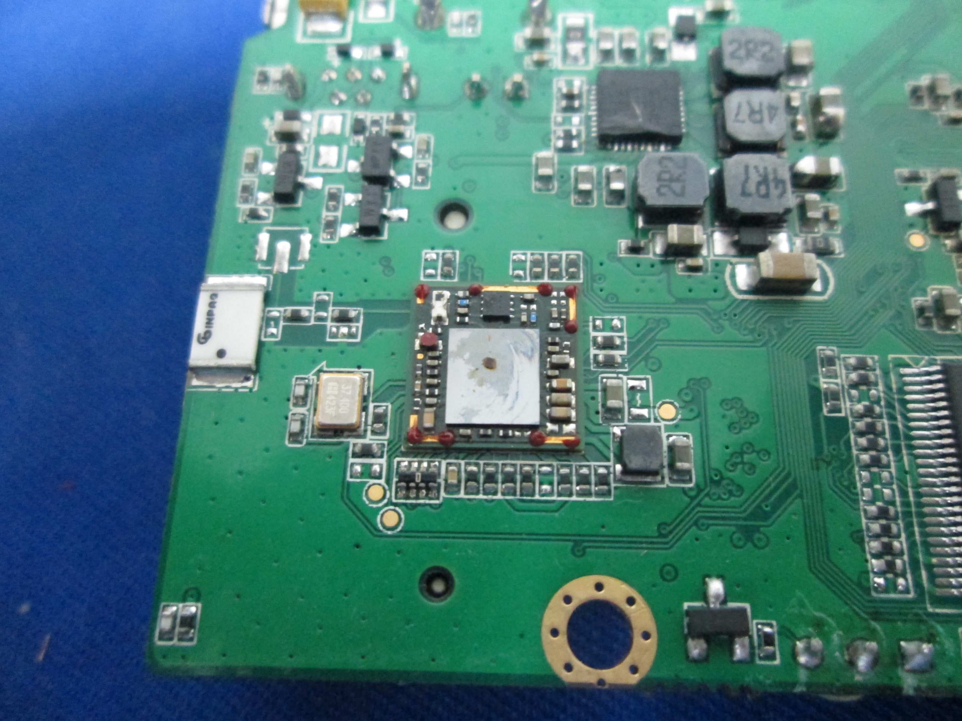
X280073
Jan 20, 2015MIPS Creator CI20 platform
Equipment Class
DTS - Digital Transmission System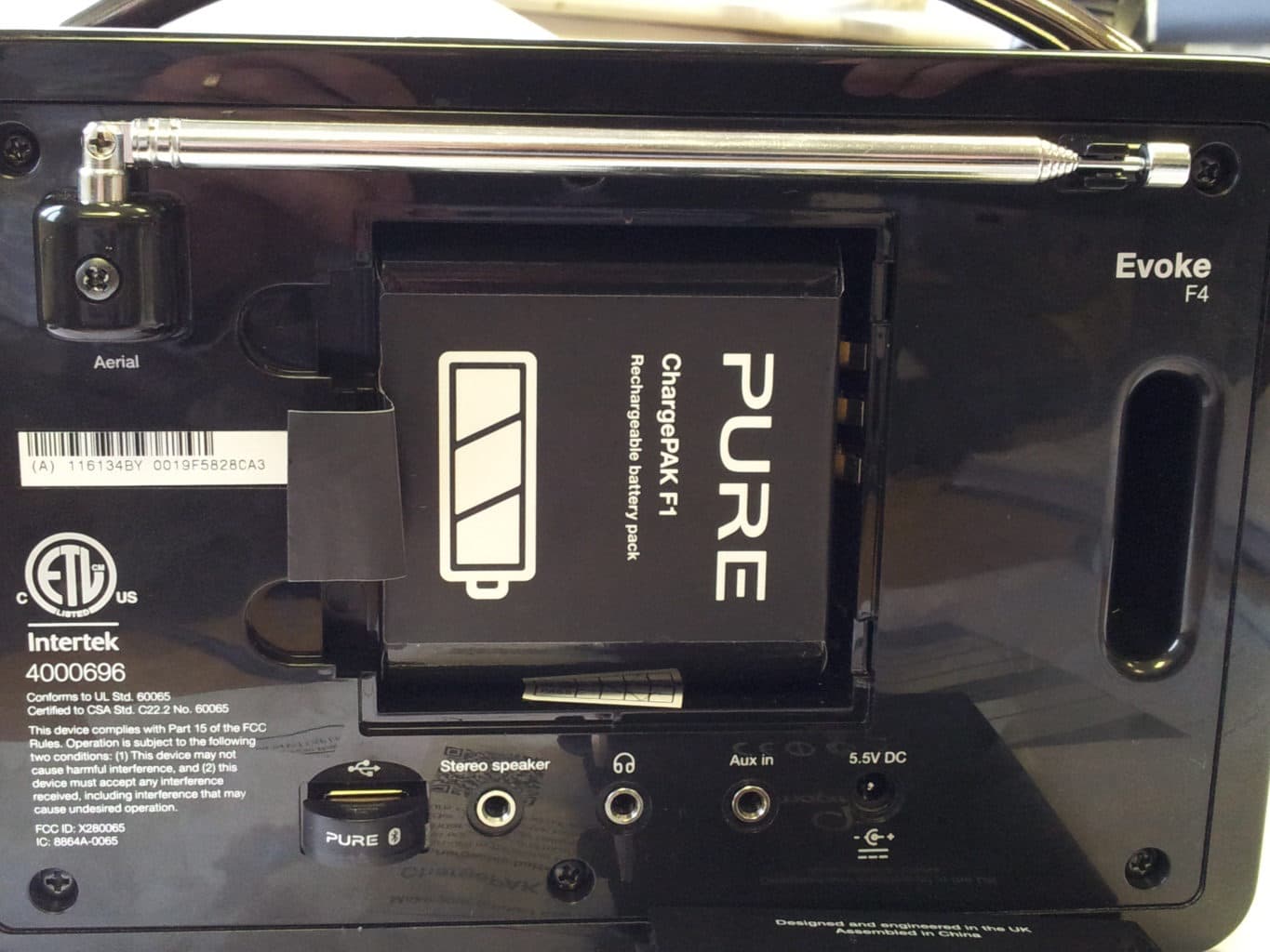
X280065
Feb 02, 2014Evoke F4
Equipment Class
DTS - Digital Transmission System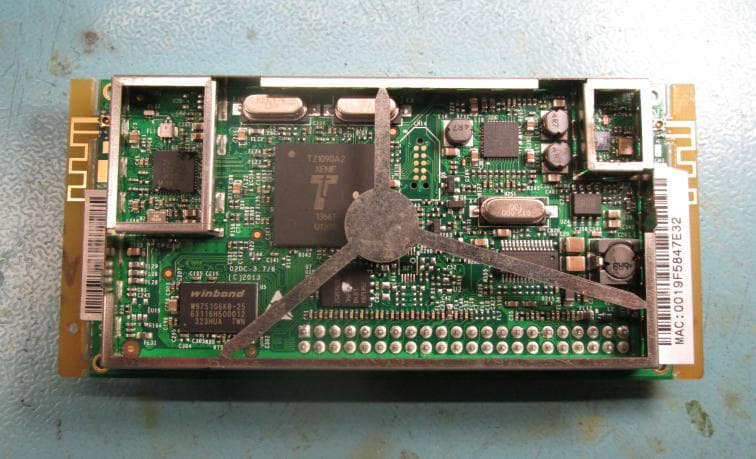
X280072
Feb 02, 2014Cougar Module Type A
Equipment Class
DSS - Part 15 Spread Spectrum Transmitter
X280067
Aug 11, 2013Jongo T6
Equipment Class
DTS - Digital Transmission System
X280070
Aug 03, 2013Jongo T2
Equipment Class
DTS - Digital Transmission System