X280056Spread Spectrum Transceiver
Imagination Technologies Ltd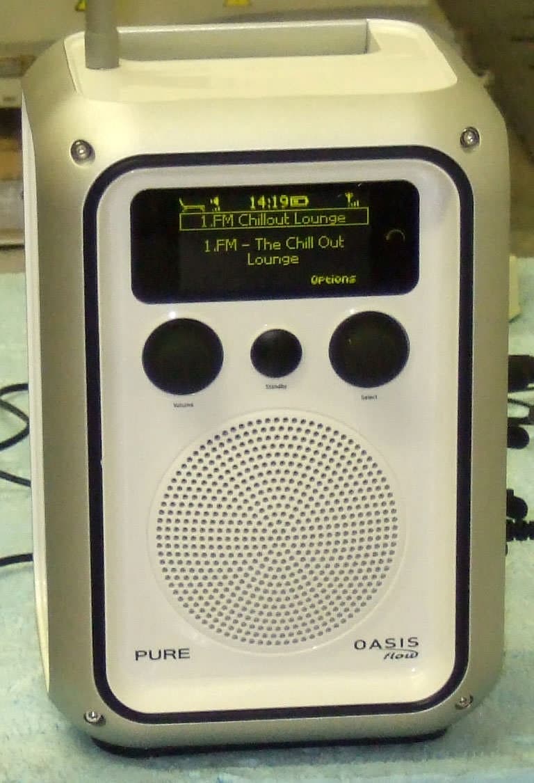
Click to zoom
Application Details
- Equipment Class
- DTS - Digital Transmission System
- Date of Grant
- Oct 01, 2010
- Application Purpose
- Original Equipment
- Date of Application
- Sep 30, 2010
- Equipment Note
- Spread Spectrum Transceiver
- Frequency Range
- 2412.00000000 - 2462.00000000
- Company
- Imagination Technologies Ltd
- Country
- United Kingdom
Documents & Files
Document Text
Text extracted from the exhibit documents filed with the FCC. Open a document above to read the original.
Users Manual
Quickstart Guide Guide de démarrage rapide Guía de inicio rápido En Fr Es LINCOLN_OASIS_Flow_ML.indb 124/06/2010 11:20:58 2 Getting started 3 Using the controls 4 About the icon bar 5 Listening to FM radio 6 Connecting to the internet 7 Listening to internet radio 8 Listening to other internet content 9 The Lounge 10 Streaming music from your computer 11 Connecting an iPod or auxiliary device 13 Safety instructions 15 Contents This Quickstart will familiarize you with the basic controls and functions of your Oasis Flow. For in-depth functions, please refer to the Owner’s Manual at support.pure.com. LINCOLN_OASIS_Flow_ML.indb 224/06/2010 11:20:58 3 Screw the aerial into the socket on the top panel of your Oasis Flow. Insert the connector of the supplied power adapter into the 12V DC input on the side of the radio. Plug the adapter into the power supply. Oasis Flow is displayed briefly on-screen. Choose your on-screen language (English, French, or Spanish) by turning the Select dial to scroll to and highlight the language you want. Push the Select dial in to confirm your choice. Repeat this process to select the time zone and region closest to you. Finally, select your network connection type from Wi-Fi or USB ethernet. (Mini USB Ethernet adapter available as an accessory.) The audio source screen is displayed, showing the following options: The Lounge (internet content) See pages 8-11 Media player See pages 14-15 FM radio See page 7 Auxiliary input See page 16 Getting started The Lounge Media player FM radio Auxiliary input To keep Oasis Flow weatherproof, push connectors in firmly and ensure that the rubber covers on unused sockets are closed. En Fr Es LINCOLN_OASIS_Flow_ML.indb 324/06/2010 11:21:02 4 1. Volume dial Turn to adjust volume. Push to mute and un-mute. 2. Select dial Turn to browse/highlight stations or options, push to select. Push to pause a media track or podcast. 3. Back Tap to go back one screen. Repeat to return to the audio source screen. 4. Standby button Press to switch the radio on or into standby (switch off if not attached to power supply). Using the controls 5. Touch area Oasis Flow has a touch sensitive area at the bottom of the display. Tap the word or icon that corresponds to the function you want to use. For example: 1 2 3 4 5 Meet Me In The Sky BTNH The World’s Enemy Track 03 Options LINCOLN_OASIS_Flow_ML.indb 424/06/2010 11:21:04 5 FM Signal strength (FM/Wi-Fi) Stereo signal (FM) ChargePAK battery level* Clock Alarm/timer set indicators Volume level About the icon bar Buzz FM OKPresetsOptions Live from The Hive! The Lounge (internet content) FM radio Media player MP Auxiliary input AUX SourceIcons SourceIcons * Oasis Flow has a built-in ChargePAK rechargeable battery. When plugged into a power supply the battery icon will be animated to show that ChargePAK is charging. Mute Wired connection active Wired connection lost En Fr Es LINCOLN_OASIS_Flow_ML.indb 524/06/2010 11:21:06 6 Listening to FM radio Extend the aerial for optimum FM reception and Select FM radio from the audio source screen. Turn the Select dial to seek to the next or previous FM station. To store an FM station as a preset Tune to the frequency you want to store as a preset and tap Presets. Turn the Select dial to highlight a preset number between 1 and 10. Tap Store to store the preset. (You can replace existing presets.) 103.30 Seek tune OKPresetsOptions OK Store Empty 1 Empty 2 Empty 3 Empty 4 Empty 5 LINCOLN_OASIS_Flow_ML.indb 624/06/2010 11:21:06 7 Once you have selected your network connection type (see page 3), select The Lounge from the audio source screen. Wireless connection Your Oasis Flow will scan for wireless networks and show them in a list. Select your network. Enter your network key or password by using the Select dial to highlight and select characters. Select sp to insert a space. Tap More... for lower-case and tap Delete to remove the last character. Tap Save to finish, your Oasis Flow will connect. Wired connection using optional Mini USB-Ethernet adapter Connect your network cable to the adapter, then connect the adapter to the mini USB socket on your Oasis Flow. The adapter USB light comes on and a connection to your network is made automatically. The wired connection status is shown on screen (see page 5). Connecting to the internet LAN USB 100Mbps ABCDEFGHIJKLM NOPQRSTUVWXYZ sp0123456789 Enter key or password DeleteSaveMore... 6578616D706C En Fr Es At this point, you can register and connect your radio with the Lounge. (See the full Owner’s Manual at support.pure.com.) LINCOLN_OASIS_Flow_ML.indb 724/06/2010 11:21:06 8 Thousands of radio stations around the world also broadcast online. To listen, select The Lounge (internet content) from the audio source screen. Your Oasis Flow will tune to an available station. Turn the Select dial to enter the Lounge home screen. Select Stations to see a list of currently available internet stations. Use the Select dial to browse the list and push to tune in. You can add a station to your favorites by tapping Add ♥. Search for a station Tap Search when browsing the station list to search for stations by Name, Genre, Country, Language, Quality (reliability/bit rate), or any combination of these. Use the Select dial to set your options and tap Go to see the list of results. My favourites♥ Stations Listen again Podcasts PURE sounds Listening to internet radio Clear all Clear GoLounge Name [All] Genre [Classical] Country [Netherlands] Language [Dutch] Quality [All] The Lounge home screen Station search screen LINCOLN_OASIS_Flow_ML.indb 824/06/2010 11:21:06 9 Select The Lounge from the audio source screen, then one of the following content types: Listen again Some stations offer a ‘listen again’ facility, letting you catch up with anything you might have missed. These archived radio programmes are available to listen to for a set period of time after the live broadcast. Podcasts Podcasts are pre-recorded audio shows on a wide variety of s…
Text truncated - open the document above for the full version.
Cover Letter(s)
RequestforConfidentiality Date:17 th June2010__ Subject: Confidentiality Request for FCC ID:__X280056____ Pursuant to FCC 47 CRF 0.457(d) and 0.459 and IC RSP-100, Section 10,the applicantrequests that a part of the subject FCC application be held confidential. Type of Confidentiality RequestedExhibit Short TermPermanentBlock Diagrams Short TermExternal Photos Short TermPermanent* 1 Internal Photos Short TermPermanentOperation Description/Theory of Operation Short TermPermanentParts List & Placement/BOM Short TermPermanentTune-Up Procedure Short TermPermanentSchematics Short TermTest Setup Photos Short TermPermanent*User’s Manual *Note:______(Insert Explanation as Necessary)______ Imagination Technologies Ltd / Pure Digitalhas spent substantial effort in developing this product and it is one of the first of its kind in industry. Having the subject information easily available to "competition" would negate the advantage theyhave achieved by developing this product. Not protecting the details of the design will result in financial hardship. Permanent Confidentiality: The applicant requests the exhibits listed above as permanently confidential be permanently withheld from public reviewdue to materials that contain trade secrets and proprietary information not customarily released to the public. Short-Term Confidentiality: Not applicable. Sincerely, By:________________________________JASON MILLER___________
External Photos
ExternalPhotos
ID Label/Location Info
This device complies with Part 15 of the FCC Rules. Operation is subject to the following two conditions:(1) This device may not cause harmful interference, and (2) this device must accept any interference received, including interference thatmay cause undesired operation. FCC ID: X280056 IC: 8864A-0056
Internal Photos
PURE OASIS Flow – internal photos V1 15-June-2010 Internal View – Front and rear cabinets opened. Rear Connector PCB – back Rear Connector PCB – top ‘Rufus’ Main Module – top side with screening can fitted Chip Antenna WiFi Chipset ‘Rufus’ Main Module – top side with screening can removed ‘Rufus’ Main Module – back side Main Power and Audio PCB – rear side with screening can fitted Main Power and Audio PCB – rear side with screening can removed Main Power and Audio PCB – front side with screening can fitted Main Power and Audio PCB – front side with screening can removed Touchscreen on PET
RF Exposure Info
OasisFlowRF Exposure:- TheOasisFlow is intended as a mobile device. A warning statement is included in the user manual advising users to maintain a minimum distance of 20cm. Evaluation is therefore for exposure potential against the MPElimits given in Appendix A of OET Bulletin 65, Supplement C: 1500-100,000MHz; 1mW/cm 2 Compliance requirements are based upon General population / Uncontrolled exposure. Equation (3) of OET Bulletin 65: ܵ= ܩܲ 4ߨܴ ଶ where:S = power density (in appropriate units, e.g. mW/cm 2 ) P = power input to the antenna (in appropriate units, e.g. mW) G = power gain of the antenna in the direction of interest relative to an isotropic radiator R = distance to the centre of radiation of the antenna (appropriate units, e.g. cm) Substituting known values for the OasisFlow: WiFi RFworst caseaverage power, P = 17.8mW. WiFi antenna gain (measured), G = 0.75. n.b.although the specified gain for the chip antenna is 0dBi, this is thebest gain (high channel gain)measured in practice. Distance, R = 20cm(for mobile use). S =0.0027< 1mW/cm 2
Test Report
File namePURE.412PAGE1OF111 QMF21J–3: FCC PART 15C: RNEISSUE 01:-APR 10 FCC47CFRpart 15C Test Report For Oasis Flow Reference Standard: FCC47CFRpart 15C Manufacturer: Pure Digital Ltd For type of equipment and serial number, refer to section 3 Report Number: 06-412/4248/5/10 Report Producedby:-R.N. Electronics Ltd. 1 Arnolds Court Arnolds Farm Lane Mountnessing Essex CM13 1UT U.K. www.RNelectronics.comTelephone+44 (0) 1277 352219 Facsimile+44 (0) 1277 352968 2004RN ELECTRONICS LIMITEDREPORT NUMBER06-412/4248/5/10 ALL RIGHTS RESERVED File namePURE.412PAGE2OF111 QMF21J–3: FCC PART 15C: RNEISSUE 01:-APR 10 1.Contents 1.CONTENTS.................................................................................................................................................................................2 2.SUMMARYOFTESTRESULTS.................................................................................................................................................3 3.EQUIPMENTUNDERTEST(EUT)..........................................................................................................................................4 3.1Equipment Specification............................................................................................................4 3.2EUT Configurations for testing.................................................................................................4 3.3EUT Modes.................................................................................................................................4 3.4Emissions Configuration............................................................................................................6 4.SPECIFICATIONS........................................................................................................................................................................7 4.1Deviations...................................................................................................................................7 4.2Tests at Extremes of Temperature & Voltage...........................................................................7 4.3Measurement Uncertainties........................................................................................................7 5.TESTS,METHODS ANDRESULTS............................................................................................................................................8 5.1Conducted Emissions.................................................................................................................8 5.2Radiated Emissions.....................................................................................................................9 5.3Peak Conducted Power.............................................................................................................11 5.4Frequency Tolerance.................................................................................................................13 5.5Duty Cycle................................................................................................................................13 5.6Maximum Spectral Power Density..........................................................................................14 5.76dB Bandwidth.........................................................................................................................15 5.8Band Edge Compliance............................................................................................................17 5.9Frequency Separation................................................................................................................19 5.10Number of hopping Channels...................................................................................................19 6.PLOTS ANDRESULTS.............................................................................................................................................................20 6.1Conducted Emissions...............................................................................................................20 6.2Radiated Emissions...................................................................................................................24 6.3Fundamental Emissions............................................................................................................47 6.4Duty Cycle.................................................................................................................................50 6.56dB Bandwidth.........................................................................................................................51 6.6Band Edge Compliance............................................................................................................71 6.7Frequency separation................................................................................................................97 6.8Number of hopping channels....................................................................................................98 7.EXPLANATORYNOTES..........................................................................................................................................................99 7.1Explanation of FAIL LIMIT 1 Statement.................................................................................99 7.2Explanation of limit line calculations for radiated measurements.........................................99 8.PHOTOGRAPHS....................................................................................................................................................................100 9.SIGNALLEADS.....................................................................................................................................................................105 10.TESTEQUIPMENTCALIBRATION LIST.........................................................................................................…
Text truncated - open the document above for the full version.
Test Report
TCB Questions. Applicant answers. Question 1: Please confirm that the device was operating at maximum power during the RF tests. The operation description document states that the device is capable of transmitting up to 17 dBm (802.11b) and 15 dBm (802.11g) with an absolute maximum of 20 dBm. Section 3.2 of the test report states an overall rating of 18 dBm. Section 5.3 of the report shows a measured maximum value of 12.9 dBm. Please explain. Answer 1: We confirm that the device was operating on maximum power. The manufacturer’s rating is based on the optimistic technical data provided by the chip and antenna manufacturers. The actual power achieved is lower in practice and consistent with expectations, due to matching, layout, etc. Question 2: I see that the user can select regions and timezones on this device. Please confirm that it is not possible for the user to select channels outside of the certified frequency range. Answer 2: The user region select feature only provides for local timezone selection.
Test Setup Photos
Test Setup Photos Emissions up to 30MHz: Emissions 30MHz–1GHz: Emissions 1–18 GHz: Emissions above 18GHz: Conducted emissions:
Contact Information
Applicant
Jason Miller(Quality Manager)
Technical Contact
Imagination Technologies LtdCarl French
Home Park Estate · Kings Langley · United Kingdom
Test Firm
R.N. Electronics Ltd.Roger Ray
Technical Specifications
| # | Rule Parts | Frequency Range | Power Output |
|---|---|---|---|
| 1 | 15C | 2.41 GHz - 2.46 GHz | 20.00 mW |
Other Applications from Imagination Technologies Ltd
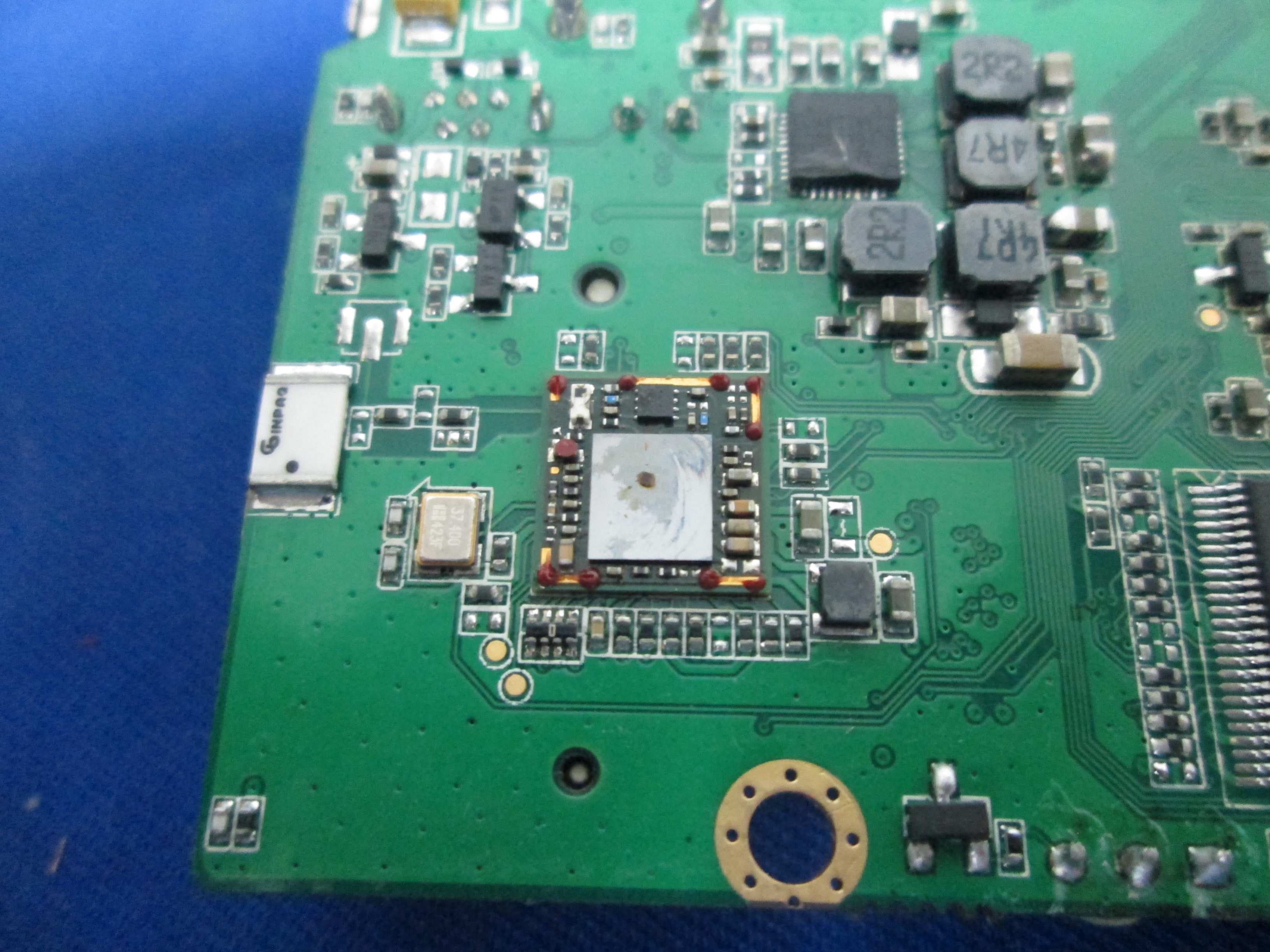
X280073
Jan 20, 2015MIPS Creator CI20 platform
Equipment Class
DTS - Digital Transmission System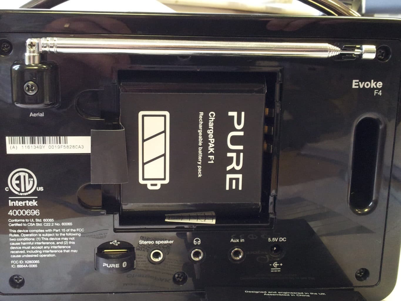
X280065
Feb 02, 2014Evoke F4
Equipment Class
DTS - Digital Transmission System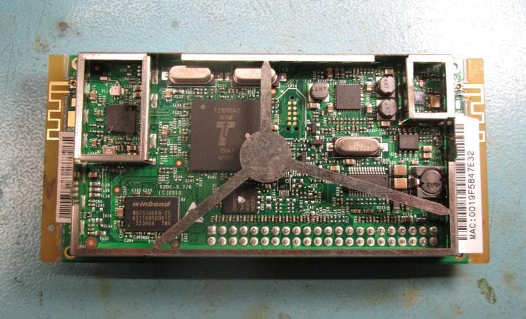
X280072
Feb 02, 2014Cougar Module Type A
Equipment Class
DSS - Part 15 Spread Spectrum Transmitter
X280067
Aug 11, 2013Jongo T6
Equipment Class
DTS - Digital Transmission System
X280070
Aug 03, 2013Jongo T2
Equipment Class
DTS - Digital Transmission System