X280062PURE Contour
Imagination Technologies Ltd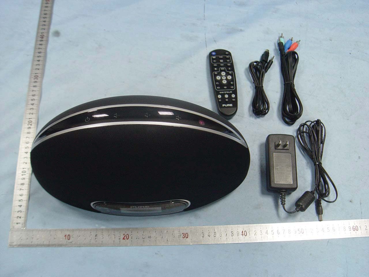
Click to zoom
Application Details
- Equipment Class
- DTS - Digital Transmission System
- Date of Grant
- Jul 20, 2011
- Application Purpose
- Original Equipment
- Date of Application
- Jul 20, 2011
- Equipment Note
- PURE Contour
- Frequency Range
- 2412.00000000 - 2462.00000000
- Company
- Imagination Technologies Ltd
- Country
- United Kingdom
Documents & Files
Document Text
Text extracted from the exhibit documents filed with the FCC. Open a document above to read the original.
Users Manual
Quickstart Guide Guide de démarrage rapide Guía de inicio rápido EN FR ES 2 Important safety instructions 1. Read these instructions – All the safety and operating instructions should be read before this product is operated. 2. Keep these instructions – The safety and operating instructions should be retained for future reference. 3. Heed all warnings – All warnings on the apparatus and in the operating instructions should be adhered to. 4. Follow all instructions – All operating and use instructions should be followed. 5. Do not use this apparatus near water – The appliance should not be used near water or moisture – for example, near a swimming pool. 6. Clean only with dry cloth. 7. Do not block any ventilation openings. Install in accordance with the manufacturer’s instructions. 8. Do not install near any heat sources such as radiators, heat registers, stoves, or other apparatus (including amplifi ers) that produce heat. 9. Do not defeat the safety purpose of the polarized or grounding plug. A polarized plug has two blades with one wider than the other. A grounding plug has two blades and a third grounding prong. The wide blade or the third prong is provided for your safety. If the provided plug does not fi t into your outlet, consult an electrician. 10. Only use attachments or accessories specifi ed by the manufacturer. 11. Unplug the apparatus during lightning storms or when unused for long periods of time. 12. Refer all servicing to qualifi ed personnel. Servicing is required when the apparatus has been damaged in any way, such as power supply cord or plug is damaged, liquid has been spilled or objects have fallen into the apparatus has been exposed to rain or moisture, does not operate normally, or has been dropped. 13. Do not install this equipment in a confi ned or built-in space such as a bookcase or similar unit. The ventilation should not be impeded by covering the ventilation openings with items such as newspaper, tablecloths, curtains etc. 14. WARNING: To reduce the risk of fi re or electric shock, do not expose this apparatus to rain, moisture, dripping or splashing. Objects fi lled with liquids, such as vases, should not be placed on apparatus. 15. WARNING: The power adapter is used to disconnect the apparatus from mains power. It must remain readily accessible. 16. WARNING: The remote batteries should not be exposed to excessive heat or fi re. 17. This equipment is a Class II or double insulated electrical appliance. It has been designed in such a way that it does not require a safety connection to electrical earth. 18. Separation distance of at least 20cm must be maintained between the antenna of the product and all persons. 19. The power rating marking is located on the base of the main unit. 3 EN This Quickstart will familiarize you with the basic controls and functions of your Contour. For in-depth functions, please refer to the Owner’s Manual at http://support.pure.com/us. Contents Guide to controls and connectors 4 Getting started 6 Connecting an iPod or iPhone 7 Connecting to the internet 8 Listening to internet radio 8 Listening to other internet content 8 The Lounge website 9 FlowSongs – identify and buy music 9 Media Player – stream music to your radio 10 Listening to FM radio 10 Options 11 Technical specifi cations 12 4 Top panel Front panel Rear connectors Guide to controls and connectors All of Contour’s controls are touch sensitive. Tap or hold a fi nger on the button you want to use. 20 Standby Tap to switch between on and standby Home Tap to return to the audio sour ce screen Volume up Tap or hold to raise volume Volume down Tap or hold to lower volume Navigation buttons Tap to navigate and select menu options Mute Tap to mute Back Tap to go back one step Context-sensitive buttons Active buttons are lit and the function is displayed on-scr een above the button 20V DC input Input for mains adapter Headphones 3.5 mm socket for headphones Aux In 3.5 mm connection for auxiliary devices Component/S-Video 3.5mm video output from a docked iPod/iPhone. (PURE Choice accessory cables available separately .) Composite Phono video output fr om a docked iPod/ iPhone. Connect to a TV or monitor Mini USB For software updates and optional PURE Ether net adapter 5 EN Media Player/iPod only Shuffl e track playback order. Repeat – Toggle repeat all or repeat current track Video Switch between Component/S-V ideo and Composite video output. Media player/Podcast/Listen Again/iPod Play/pause current track. Skip to start of curr ent track or go to previous track. Hold to fast rewind. Skip to end of current track or start of the next track. Hold to fast forward. Add or recall a favorite station Options Enter option settings Change on-screen information Navigate menus OK Confi rm a selection Home. Display the audio source screen Increase the volume Decrease the volume Back. Go back one step Remote control Switch between On and Standby Mute audio Sources Select a source to listen to Sleep Press to start sleep timer Repeat to incr ease time Alarm Enter Alarm setup Tone Adjust Bass and Treble Context-sensitive (match buttons on front panel) Left [ ] Centre [ ] Right [ ] 6 Source Icons Buzz FM OKPresets Live from The Hive! SourceIcons Getting started 1. Extend the aerial. 2. Insert the batteries into the remote control. 3. Insert the connector of the supplied power adapter into the 20V input on the back of the radio, plug into the power supply and switch on. 4. Choose your on-screen language ( English, French or Spanish) using the r emote or navigation buttons. Repeat this process to select the time zone and region closest to you. 5. Select your network connection type from Wi-Fi or Ethernet (PURE Mini USB Ethernet adapter available as an accessory). When you have selected your preferences, the audio source screen will be displayed (see below) and you can explore Contour. The Lounge Media player iPod FM radio Auxiliary input Signal strength (FM/Wi-Fi) When using PURE mini USB Ethernet…
Text truncated - open the document above for the full version.
Attestation Statements
Date: July 20, 2011 To: Federal Communications Commission 7435 Oakland Mills Road Columbia, MD FCC ID: X280062 To Whom It May Concern: This letter is to ascertain that Imagination Technologies Ltd/ Pure. Product PURE Contour has been the units used for conducting FCC compliance testing, the DoC part will be tested by FCC recognized test lab. If you have any question or concerns, pls. contact us. Sincerely, Jason Miller Quality Manager
ID Label/Location Info
FCC Certification label Sample FCC Certification Label Location Sample Label location
Internal Photos
Antenna
RF Exposure Info
1. RF EXPOSURE 1.1. The Requirement System operating under the provisions of this section shall be operated in a manner that ensures that the public is not exposed to radio frequency energy levels in excess of the Commission’s guidelines. See Section 15.247(b)(4) and Section 1.1307(b)(1) 1.2. Limit For Maximum Permissible Exposure (MPE) Limits for General Population/ Uncontrolled Exposure F = frequency in MHz, * Plane-wave equivalent power density 1.3. MPE Calculations E(V/m) = 30 P G d , Power Density: S( 2 mW/cm) = 2 377 E Where E = Electric Field (V/m) P = Peak Output Power (mW) G = Antenna Numeric Gain (numeric) = 10 x , x = Antenna Gain(dBi) /10 d = Separation Distance (cm) Frequency Range (MHz) Electric Field Strength (E) (V/m) Magnetic Field Strength (H) (A/m) Power Density (S) ( 2 mW/cm) Averaging Time 2 E, 2 H or S (minutes) 0.3-1.34 614 1.63 (100)* 30 1.34-30 824/f 2.19/f (180/f)* 30 30-300 27.5 0.073 0.2 30 300-1500 f/1500 30 1500-100,000 1.0 30 We can change the formula to: S = 2 30 377 PG d or, d = 30 377 PG S Because the EUT is belong to general population/uncontrolled exposure. So 1.3.1. We considering the limit of minimum separation distance (d) is 20cm, Maximum Output Power = 26.3mW Antenna Gain = 0(dBi) = 1(numeric) S = 2 30 377 PG d = 0.005 2 mW/cm < 1.0 2 mW/cm (limit) Calculated RF Exposure power density is 0.005 2 mW/cm , less than the limit. 1.3.2. We considering the limit of power density (S) is 1.0 2 mW/cm , Maximum Output Power = 26.3mW Antenna Gain = 0(dBi) = 1 (numeric) d = 30 377 PG S = 1.4 cm < 20 cm Calculated RF Exposure separation distance is 1.4 cm, less than the minimum separation distance 1.3.3.FCC Radiation Exposure Statement This equipment complies with FCC radiation exposure limits set forth for an uncontrolled environment. In order to avoid the possibility of exceeding the FCC radio frequency exposure limits, Human proximity to the antenna shall not be less than 20cm(8 inches) during normal operation. Proposed RF exposure safety information to include in User’s Manual.
Test Report
Page 1 of 103 FCC ID: X280062 ACCURATE TECHNOLOGY CO., LTD Report No.: ATE20110148 APPLICATION CERTIFICATION FCC Part 15C On Behalf of Imagination Technologies Ltd / Pure PURE Contour Model No.: VL-61394 FCC ID: X280062 Prepared for : Imagination Technologies Ltd / Pure Address : Home Park Estate, Kings Langley, Hertfordshire, WD4 8LZ, United Kingdom Prepared by : ACCURATE TECHNOLOGY CO., LTD Address : F1, Bldg. A, Changyuan New Material Port, Keyuan Rd. Science & Industry Park, Nanshan, Shenzhen, Guangdong P.R. China Tel: (0755) 26503290 Fax: (0755) 26503396 Report Number : ATE20110148 Date of Test : February 14-22, 2011 Date of Report : February 28, 2011 Page 2 of 103 FCC ID: X280062 ACCURATE TECHNOLOGY CO., LTD Report No.: ATE20110148 TABLE OF CONTENTS Description Page Test Report Certification 1. GENERAL INFORMATION .......................................................................................................... 5 1.1. Description of Device (EUT)....................................................................................................................5 1.2. Description of Test Facility ......................................................................................................................6 1.3. Measurement Uncertainty.........................................................................................................................6 2. MEASURING DEVICE AND TEST EQUIPMENT ..................................................................... 7 3. OPERATION OF EUT DURING TESTING ................................................................................. 8 3.1. Operating Mode ........................................................................................................................................8 3.2. Configuration and peripherals ..................................................................................................................8 4. TEST PROCEDURES AND RESULTS ......................................................................................... 9 5. 6DB BANDWIDTH MEASUREMENT ........................................................................................ 10 5.1. Block Diagram of Test Setup..................................................................................................................10 5.2. The Requirement For Section 15.247(a)(1) ............................................................................................10 5.3. EUT Configuration on Measurement .....................................................................................................10 5.4. Operating Condition of EUT ..................................................................................................................10 5.5. Test Procedure ........................................................................................................................................11 5.6. Test Result ..............................................................................................................................................11 6. MAXIMUM PEAK OUTPUT POWER ....................................................................................... 18 6.1. Block Diagram of Test Setup..................................................................................................................18 6.2. The Requirement For Section 15.247(b)(3)............................................................................................18 6.3. EUT Configuration on Measurement .....................................................................................................18 6.4. Operating Condition of EUT ..................................................................................................................18 6.5. Test Procedure ........................................................................................................................................19 6.6. Test Result ..............................................................................................................................................19 7. POWER SPECTRAL DENSITY MEASUREMENT.................................................................. 26 7.1. Block Diagram of Test Setup..................................................................................................................26 7.2. The Requirement for Section 15.247(e) .................................................................................................26 7.3. EUT Configuration on Measurement .....................................................................................................26 7.4. Operating Condition of EUT ..................................................................................................................26 7.5. Test Procedure ........................................................................................................................................27 7.6. Test Result ..............................................................................................................................................27 8. BAND EDGE COMPLIANCE TEST ........................................................................................... 34 8.1. Block Diagram of Test Setup..................................................................................................................34 8.2. The Requirement for Section 15.247(d) .................................................................................................34 8.3. EUT Configuration on Measurement .....................................................................................................34 8.4. Operating Condition of EUT ..................................................................................................................35 8.5. Test Procedure ........................................................................................................................................35 8.6. Test Result ....…
Text truncated - open the document above for the full version.
Test Setup Photos
Conducted emissions test Radiated emissions test < 1GHz Radiated emissions test > 1GHz
Contact Information
Applicant
Jason Miller(Quality Manager)
Test Firm
Accurate Technology Co., Ltd.Sean Liu
Technical Specifications
| # | Rule Parts | Frequency Range | Power Output |
|---|---|---|---|
| 1 | 15C | 2.41 GHz - 2.46 GHz | 26.30 mW |
Other Applications from Imagination Technologies Ltd
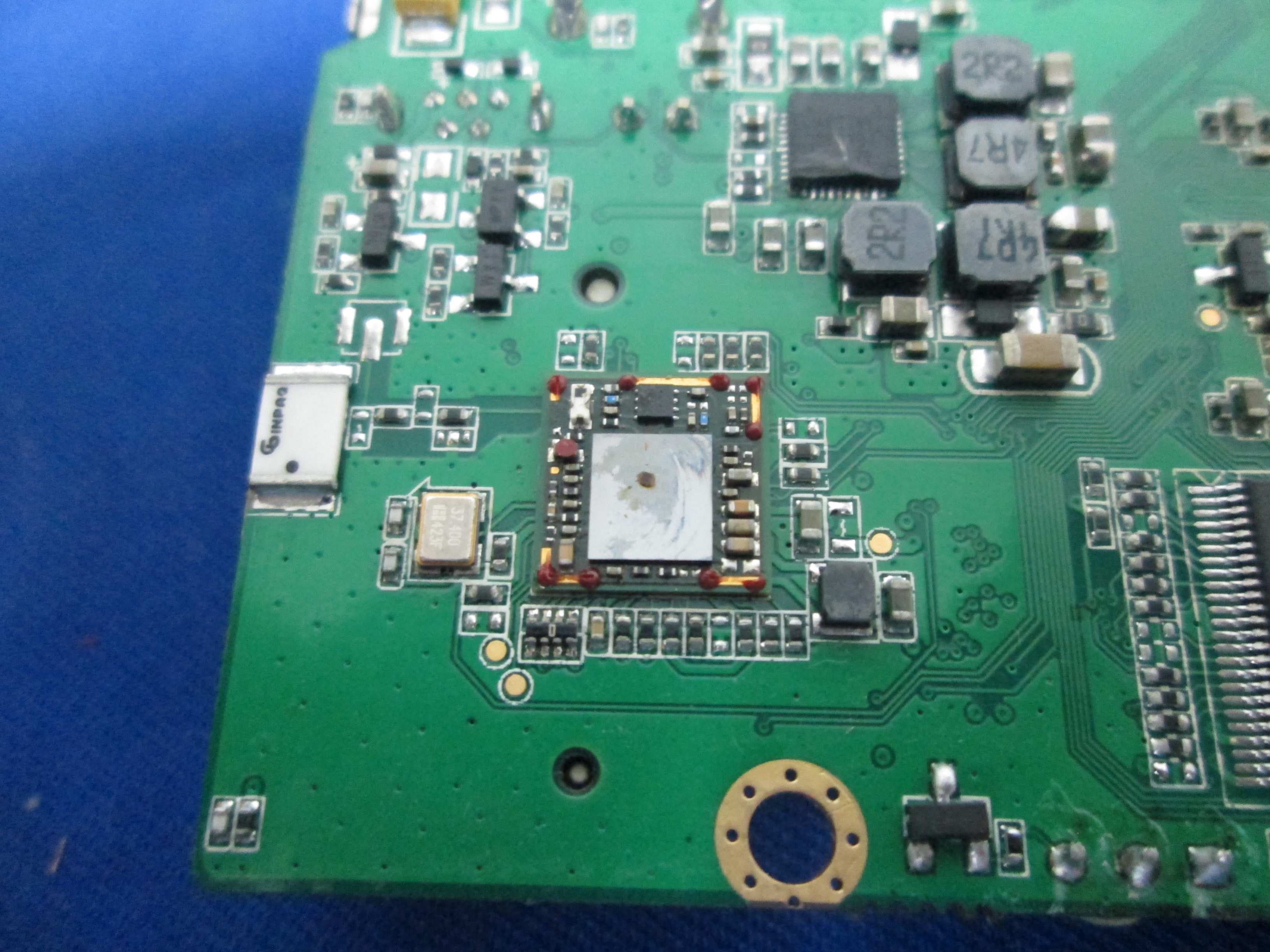
X280073
Jan 20, 2015MIPS Creator CI20 platform
Equipment Class
DTS - Digital Transmission System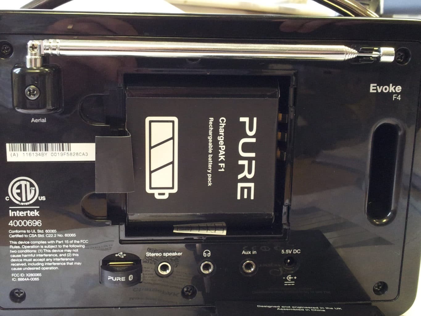
X280065
Feb 02, 2014Evoke F4
Equipment Class
DTS - Digital Transmission System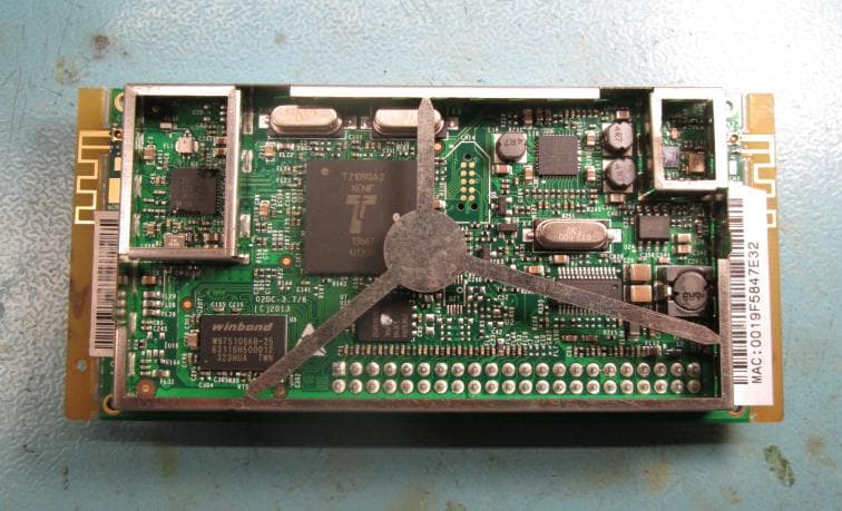
X280072
Feb 02, 2014Cougar Module Type A
Equipment Class
DSS - Part 15 Spread Spectrum Transmitter
X280067
Aug 11, 2013Jongo T6
Equipment Class
DTS - Digital Transmission System
X280070
Aug 03, 2013Jongo T2
Equipment Class
DTS - Digital Transmission System