X280063Airplay and Docking Music Player for iPod/iPhone/iPad
Imagination Technologies Ltd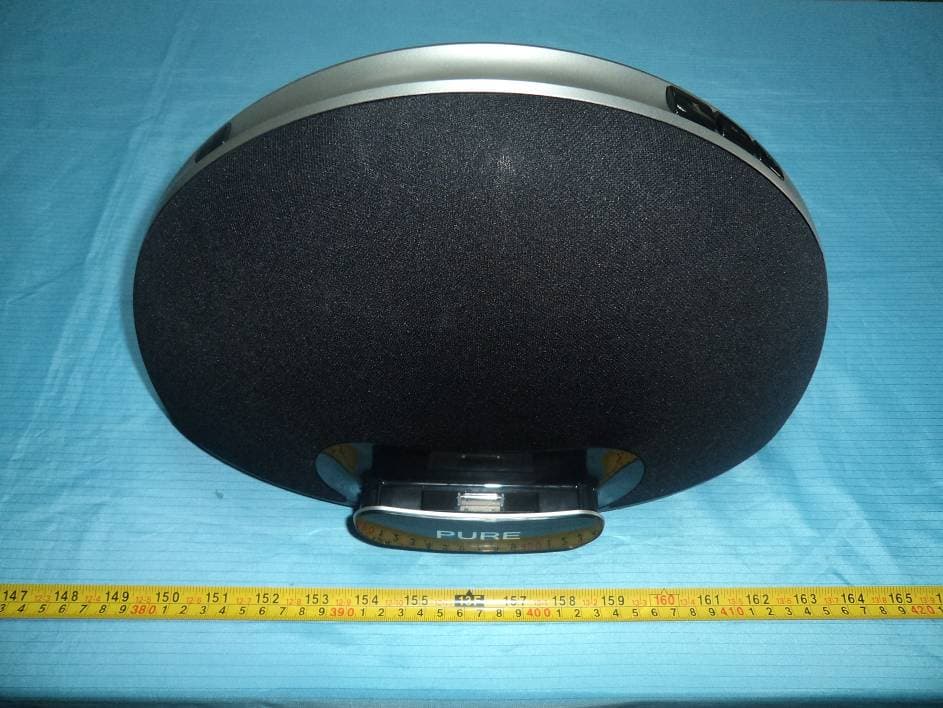
Click to zoom
Application Details
- Equipment Class
- DTS - Digital Transmission System
- Date of Grant
- Dec 21, 2011
- Application Purpose
- Original Equipment
- Date of Application
- Dec 21, 2011
- Equipment Note
- Airplay and Docking Music Player for iPod/iPhone/iPad
- Frequency Range
- 2412.00000000 - 2462.00000000
- Company
- Imagination Technologies Ltd
- Country
- United Kingdom
Documents & Files
Document Text
Text extracted from the exhibit documents filed with the FCC. Open a document above to read the original.
Users Manual
Owner’s manual Safety instructions 1. Read these instructions – All the safety and operating instructions should be read before this product is operated. 2. Keep these instructions – The safety and operating instructions should be retained for future reference. 3. Heed all warnings – All warnings on the appliance and in the operating instructions should be adhered to. 4. Follow all instructions – All operating and use instructions should be followed. 5. Do not use this apparatus near water – The appliance should not be used near water or moisture – for example, in a wet basement or near a swimming pool. 6. Clean only with dry cloth. 7. Do not block any ventilation openings. Install in accordance with the manufacturer’s instructions. 8. Do not install near any heat sources such as radiators, heat registers, stoves, or other apparatus (including amplifiers) that produce heat. 9. Do not defeat the safety purpose of the polarized or grounding plug. A polarized plug has two blades with one wider than the other. A grounding plug has two blades and a third grounding prong. The wide blade or the third prong is provided for your safety. If the provided plug does not fit into your outlet, consult an electrician for replacement of the obsolete outlet. 10. Only use attachments/accessories specified by the manufacturer. 11. Unplug the apparatus during lightning storms or when unused for long periods of time. 12. Refer all servicing to qualified personnel. Servicing is required when the apparatus has been damaged in any way,such as power supply cord or plug is damaged, liquid has been spilled or objects have fallen into the apparatus has been exposed to rain or moisture, does not operate normally, or has been dropped. 13. Do not install this equipment in a confined or building-in space such as a book case or similar unit. The ventilation should not be impeded by covering the ventilation openings with items such as newspaper, tablecloths, curtains etc. 14. WARNING: To reduce the risk of fire or electric shock, do not expose this apparatus to rain or moisture. The apparatus shall not be exposed to dripping or splashing and that objects filled with liquids, such as vases, shall not be placed on apparatus. 15. The mains plug and appliance coupler are used as disconnect device, the disconnect device shall remain readily operable 16. WARNING: The remote batteries shall not be exposed to excessive heat such as sunshine, fire or the like. 17. This equipment is a Class II or double insulated electrical appliance. It has been designed in such a way that it does not require a safety connection to electrical earth. 18. Separation distance of at least 20cm must be maintained between the antenna of the product and all persons. 19. The socket-outlet shall be installed near the equipment and shall be easily accessible. FCC NOTICE TO A USER IN THE UNITED STATES This equipment has been tested and found to comply with the limits for a Class B digital device, pursuant to Part 15 of the FCC Rules. These limits are designed to provide reasonable protection against harmful interference in a residential installation. This equipment generates, uses, and can radiate radio frequency energy and, if not installed and used in accordance with the instructions, may cause harmful interference to radio communications. However, there is no guarantee that interference will not occur in a particular installation. If this equipment does cause harmful interference to radio or television reception, which can be determined by turning the equipment off and on, the user is encouraged to try to correct the interference by one or more of the following measures: • Reorient or relocate the receiving antenna. • Increase the separation between the equipment and receiver. • Connect the equipment into an outlet on a circuit different from that to which the receiver is connected. • Consult the dealer or an experienced radio/T V technician for help. Warning! Any modification or changes to this device, unless explicitly approved by PURE, will invalidate the authorisation of the device. Operation of an unauthorized device is prohibited under Section 302 of the Communications Act of 1934, as amended, and Subpart 1 of Part 2 of Chapter 47 of the Code of Federal Regulations. This device complies with part 15 of the FCC rules. Operation is subject to the following two conditions: (1) This device may not cause harmful interference, and (2) this device must accept any interference received, including interference that may cause undesired operation. This Class B digital apparatus complies with Canadian ICES-003. Copyright Copyright 2011 by Imagination Technologies Limited. All rights reserved. No part of this publication may be copied or distributed, transmitted, transcribed, stored in a retrieval system, or translated into any human or computer language, in any form or by any means, electronic, mechanical, magnetic, manual or otherwise, or disclosed to third parties without the express written permission of Imagination Technologies Limited. Trademarks Contour 200i Air, PURE, the PURE logo, PURE, the PURE logo, EcoPlus, the EcoPlus logo, Imagination Technologies, and the Imagination Technologies logo are trademarks or registered trademarks of Imagination Technologies Limited. iPad, iPod and iPhone are trademarks of Apple Inc., registered in the U.S. and other countries. “Made for iPod”, “Made for iPhone”, and “Made for iPad” mean that an electronic accessory has been designed to connect specifically to iPod, iPad or iPhone, respectively, and has been certified by the developer to meet Apple performance standards. Apple is not responsible for the operation of this device or its compliance with safety and regulatory standards. Please note that the use of this accessory with iPod, iPad or iPhone may affect wireless performance. All other product n a m e s a r e t r a d e m a r k s o f t h e i r r e s p e c t i v e c o m p a n i e s . V e r s i o n 1 D e c e m b e r…
Text truncated - open the document above for the full version.
External Photos
EXHIBIT B - EUT EXTERNAL PHOTOGRAPHS EUT - Front View EUT – Rear View EUT – Port View EUT – Bottom View EUT – Adapter View EUT – Adapter Label View
ID Label/Location Info
VL-61708 & FR051PU102 LABEL PROPOSAL DATE: Dec.13.2011 VER. 3.0 Position: 1) Protective film 1) INK: No printing. 2) MAT,L: 60u PET() 3) Size: 120x36mm PN: PE400R050100 120 mm 3 6 m m 2) Product barcode label 1 1pc is sticked on unit 1pc is sticked on retail carton 1)INK: White label with black printed text 2)MAT,L: Polyethlene 3)Size: 39.5x9.5mm PN: PHN2YR050100 POSITION: 1pc is sticked on the rear of unit Last 3 characters Product Part Number: 2YD Barcode format: EAN-128 Scan result: RWWYYPPPNNNNNN R = Product hardware revision [starts 1], WW = Two digit production week number YY = Two digit production year PPP = Product part number (last three characters of PURE 5 character part number) NNNNNN = 6 digit serial number [note these are sequential and continue from last production batch] Example barcodes: Leeds Twilight, EU/UK Radio Part number = 102KZ Example barcode: 135102KZ000001 R=1 RWWYYPPPNNNNNN 1pc is sticked on the retail carton. (Looking forward to your retail carton artwork.) RWWYYPPPNNNNNN 3) Rating Label 1pc is sticked on the bottom of unit. 1)INK: Black background with white printing 2)MAT,L: gloss self-adhesive paper+PP 3)Size: 69x39.5mm PN: PHN2YR050300 POSITION: Please see attached shipping mark document. N1600 DC Input:18V 3.61A FCC ID: X280063 IC: 8864A-0063 Made in China Contour 200i Air 69 mm 3 9 . 5 m m 3 mm 3 m m Rating Label Product barcode label Statement label 3A) 14R16 QR code product sticker 1pc is sticked on the front mark of carton. 1)INK: Black printing with white printing 2)MAT,L: Polyethlene+PP 3)Size: 40x20mm PN: PHN2YR050700 POSITION: 1pc is sticked on the front of unit This device complies with Part 15 of the FCC Rules. Operation is subject to the following two conditions: (1) This device may not cause harmful interference, and (2) this device must accept any interference received, including interference that may cause undesired operation. 3B) Statement Label 1pc is sticked on the bottom of unit 1)INK: Black background with white printing 2)MAT,L: gloss self-adhesive paper+PP 3)Size: 40x20mm 40 mm 2 0 m m 1pc is sticked on the retail carton. 4) Anti-Tamper Label for Retail Carton 1pc is sealed opening flap of retail carton. 1)INK: No printing 2)MAT,L: 25u transparent PET with single adhesive 3)Size: Diameter=40mm PN: PE400C020200 POSITION: 40 mm 6) Warning Label 1pc is sticked on the front mark of carton. 1)INK: CMYK. 2)MAT,L: gloss self-adhesive paper+PP 3)Size: 45x40mm PN: PHN2YD101600 POSITION: Please see attached shipping mark document. 5) Product barcode label 2 2pcs are sticked on the side mark of carton. 1)INK: White label with black printed text 2)MAT,L: gloss self-adhesive paper 3)Size: 90x20mm PN: PHN2YR050200 POSITION: Please see attached shipping mark document. In addition to size, Product barcode label 2 is same with the Product barcode label 1(including the barcode and serial no.,etc.). 45 mm RWWYYPPPNNNNNN 4 0 m m
Internal Photos
EXHIBIT C - EUT INTERNAL PHOTOGRAPHS EUT – Speaker View EUT – Bottom Cover off View EUT – Cover off View EUT –RF Antenna View Antenna EUT – Main Board with RF Module View EUT – Main Board Components View EUT – Main Board Circuit View EUT – RF Module Top View EUT – RF Module Shielding off Top View EUT – RF Module Bottom View EUT – E230968 Board Top View EUT – E230968 Board Bottom View EUT – Connect Board Top View EUT – Connect Board Bottom View EUT – LED Top View EUT – LED Bottom View
Test Report
Note: This test report is prepared for the customer shown above and for the equipment described herein. It may not be duplicated or used in part without prior written consent from Bay Area Compliance Laboratories Corp. This report must not be used by the customer to claim product certification, approval, or endorsement by NVLAP*, or any agency of the Federal Government. * This report contains data that are not covered by the NVLAP accreditation and are marked with an asterisk “★” (Rev.2) FCC PART 15.247 TEST REPORT For Imagination Technologies Ltd/Pure Home Park Estate, Kings Langley, Hertfordshire WD4 8LZ, United Kingdom Report Type: Original Report Product Type: Airplay and docking music player for iPod/iPhone/iPad Test Engineer: Brown Lu Report Number: RSZ111116002-00 Report Date: 2011-12-21 Reviewed By: Alvin Huang EMC Engineer Test Laboratory: Bay Area Compliance Laboratories Corp. (Shenzhen) 6/F, the 3rd Phase of WanLi Industrial Building, ShiHua Road, FuTian Free Trade Zone Shenzhen, Guangdong, China Tel: +86-755-33320018 Fax: +86-755-33320008 www.baclcorp.com.cn FCC ID: X280063 Bay Area Compliance Laboratories Corp. (Shenzhen) Report No.: RSZ111116002-00 FCC Part 15.247 Page 2 of 44 TABLE OF CONTENTS GENERAL INFORMATION.......................................................................................................................................4 PRODUCT DESCRIPTION FOR EQUIPMENT UNDER TEST (EUT) .....................................................................................4 OBJECTIVE...................................................................................................................................................................4 RELATED SUBMITTAL(S)/GRANT(S).............................................................................................................................4 TEST METHODOLOGY..................................................................................................................................................4 TEST FACILITY.............................................................................................................................................................4 SYSTEM TEST CONFIGURATION ..........................................................................................................................6 DESCRIPTION OF TEST CONFIGURATION......................................................................................................................6 EUT EXERCISE SOFTWARE..........................................................................................................................................6 EQUIPMENT MODIFICATIONS.......................................................................................................................................6 EXTERNAL I/O CABLE..................................................................................................................................................6 CONFIGURATION OF TEST SETUP.................................................................................................................................7 BLOCK DIAGRAM OF TEST SETUP................................................................................................................................7 SUMMARY OF TEST RESULTS ...............................................................................................................................8 FCC §15.247 (i) & §2.1091 - MAXIMUM PERMISSIBLE EXPOSURE (MPE).........................................................9 APPLICABLE STANDARD..............................................................................................................................................9 FCC §15.203 - ANTENNA REQUIREMENT...........................................................................................................10 APPLICABLE STANDARD............................................................................................................................................10 ANTENNA CONNECTOR CONSTRUCTION....................................................................................................................10 FCC §15.207 (a) – AC LINE CONDUCTED EMISSIONS .....................................................................................11 APPLICABLE STANDARD............................................................................................................................................11 MEASUREMENT UNCERTAINTY..................................................................................................................................11 EUT SETUP................................................................................................................................................................11 EMI TEST RECEIVER SETUP.......................................................................................................................................12 TEST PROCEDURE......................................................................................................................................................12 TEST EQUIPMENT LIST AND DETAILS.........................................................................................................................12 TEST RESULTS SUMMARY..........................................................................................................................................12 TEST DATA................................................................................................................................................................12 FCC §15.209, §15.205 & §15.247(d) - SPURIOUS EMISSIONS.............................................................................15 APPLICABLE STANDARD............................................................................................................................................15 MEASUREMENT UNCERTAINTY.........................................................…
Text truncated - open the document above for the full version.
Test Setup Photos
EXHIBIT C - TEST SETUP PHOTOGRAPHS Conducted Emissions- Front View Conducted Emissions- Side View Below 1 GHz: Spurious Radiated Emissions View Above 1 GHz: Spurious Radiated Emissions View
Contact Information
Applicant
Jason Miller(Quality Manager)
Test Firm
Bay Area Compliance Laboratory Corp. (Shenzhen)John Chan
Technical Specifications
| # | Rule Parts | Frequency Range | Power Output |
|---|---|---|---|
| 1 | 15C | 2.41 GHz - 2.46 GHz | 31.00 mW |
Other Applications from Imagination Technologies Ltd
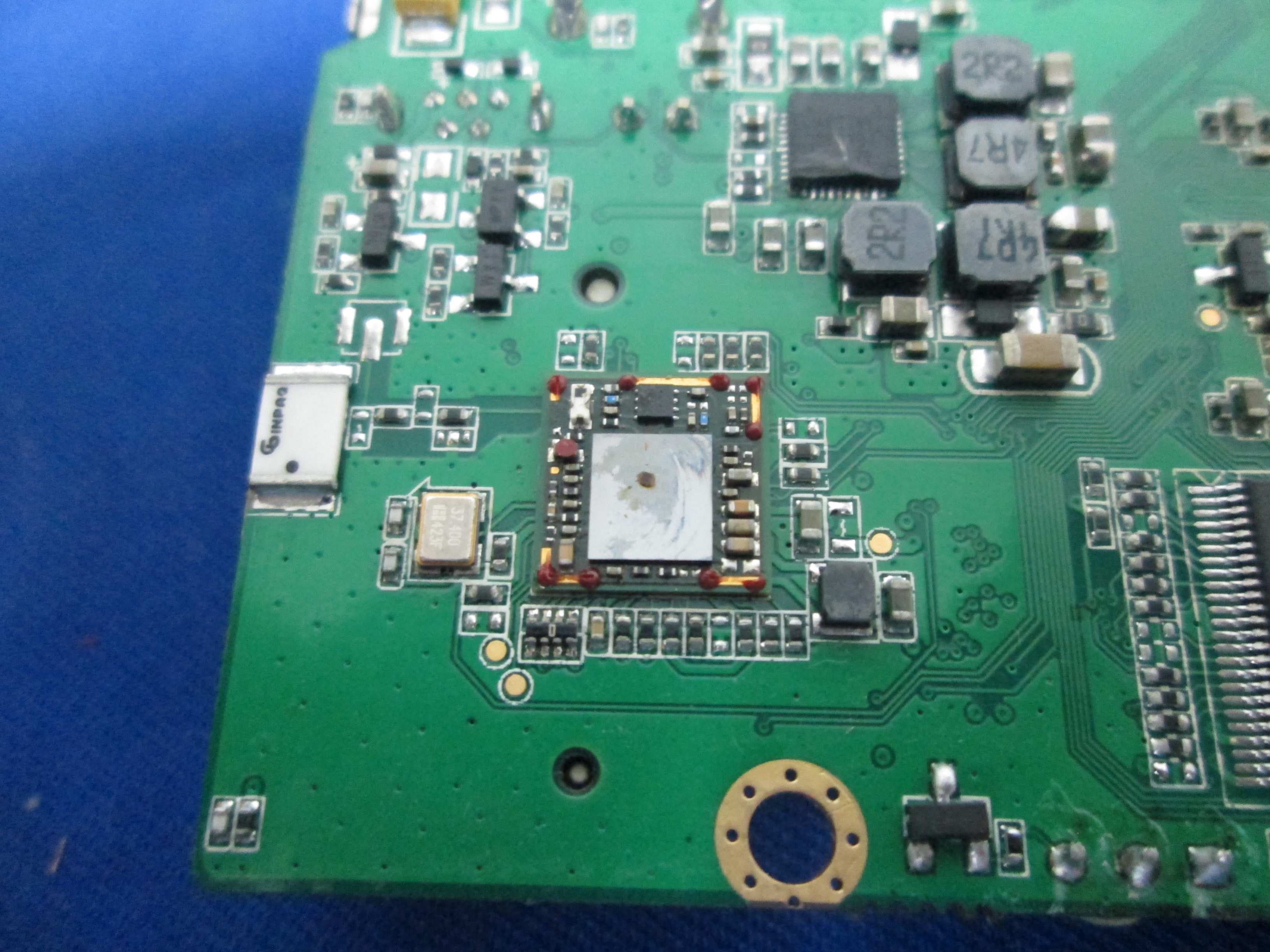
X280073
Jan 20, 2015MIPS Creator CI20 platform
Equipment Class
DTS - Digital Transmission System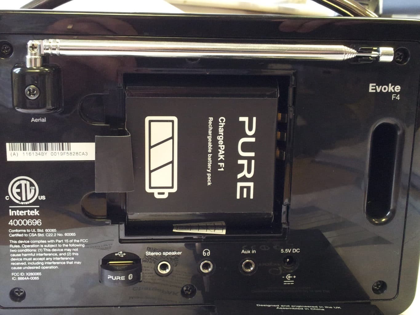
X280065
Feb 02, 2014Evoke F4
Equipment Class
DTS - Digital Transmission System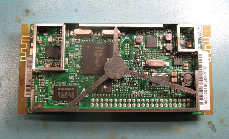
X280072
Feb 02, 2014Cougar Module Type A
Equipment Class
DSS - Part 15 Spread Spectrum Transmitter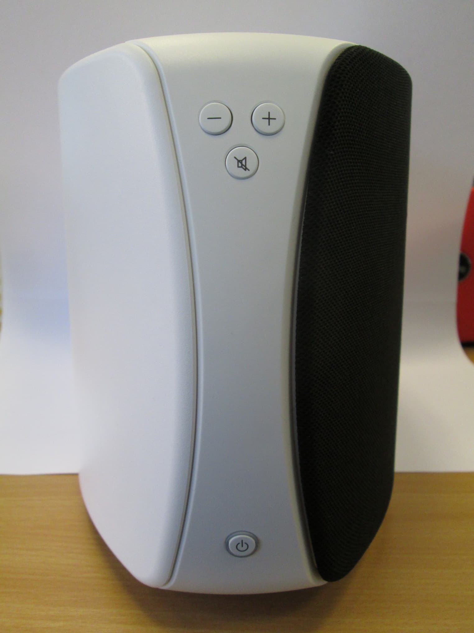
X280067
Aug 11, 2013Jongo T6
Equipment Class
DTS - Digital Transmission System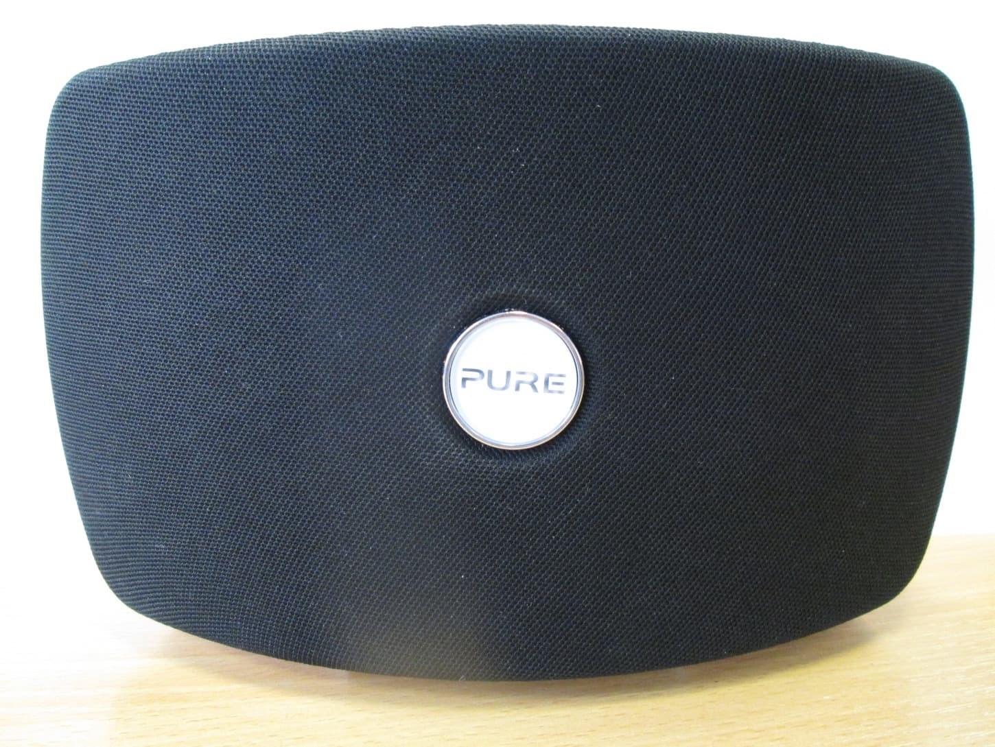
X280070
Aug 03, 2013Jongo T2
Equipment Class
DTS - Digital Transmission System