X280064Sensia 200D Connect
Imagination Technologies Ltd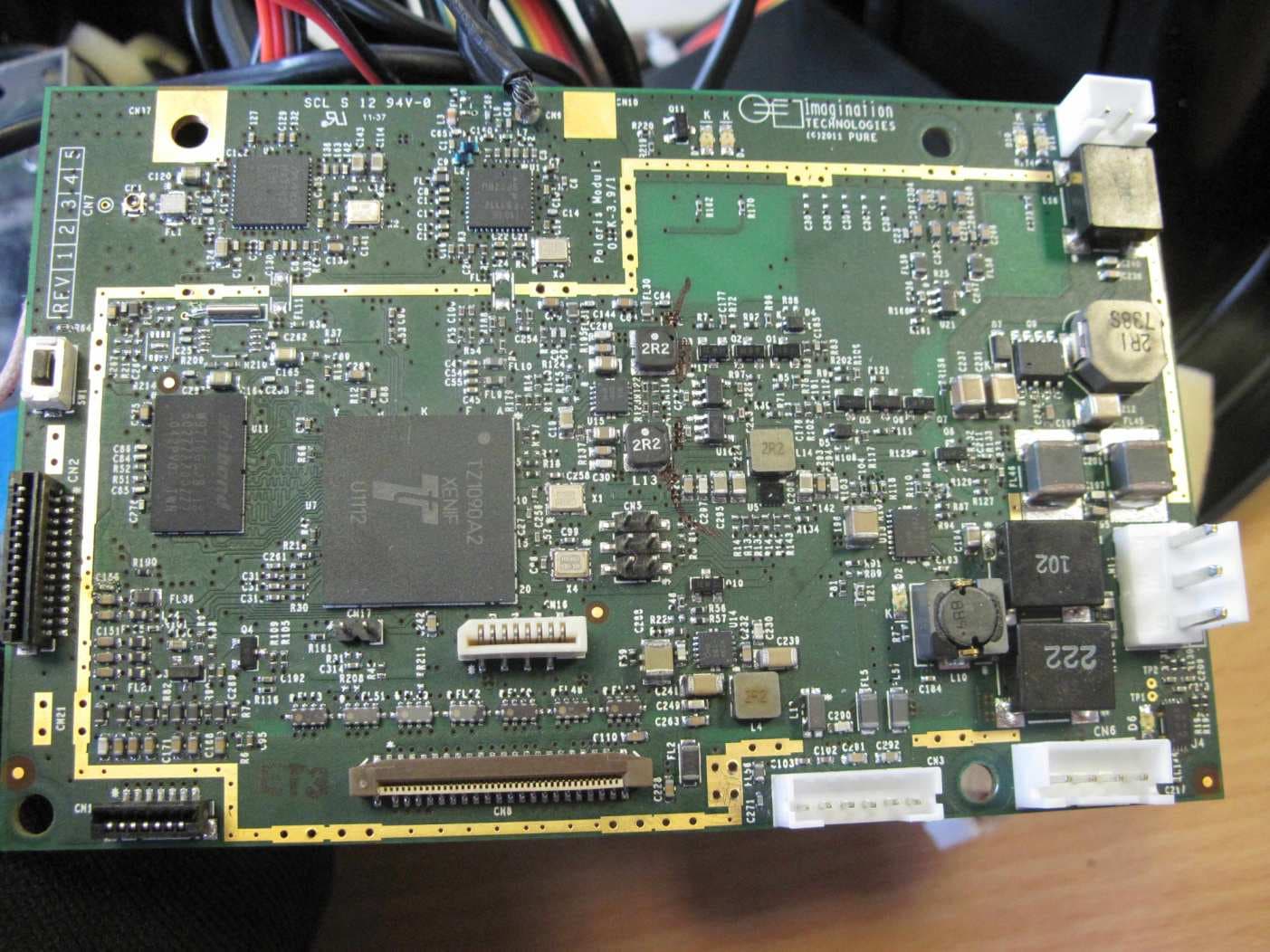
Click to zoom
Application Details
- Equipment Class
- DTS - Digital Transmission System
- Date of Grant
- Sep 27, 2012
- Application Purpose
- Original Equipment
- Date of Application
- Sep 27, 2012
- Equipment Note
- Sensia 200D Connect
- Frequency Range
- 2412.00000000 - 2462.00000000
- Company
- Imagination Technologies Ltd
- Country
- United Kingdom
Documents & Files
Document Text
Text extracted from the exhibit documents filed with the FCC. Open a document above to read the original.
Users Manual
FR ENGLISH ES 1 ENGLISH Thank you for choosing Sensia 200D Connect. This manual will get you up and running in no time and explains how to make the most of Sensia 200D Connect’s great features. If you need additional help with topics not covered in this manual, please visit the Pure support pages at www.pure.com. 2 1. Read these instructions – All the safety and operating instructions should be read before this product is operated. 2. Keep these instructions – The safety and operating instructions should be retained for futur e reference. 3. Heed all warnings – All war nings on the appliance and in the operating instructions should be adhered to. 4. Follow all instructions – All operating and use instructions should be followed. 5. Do not use this apparatus near water – The appliance should not be used near water or moisture – for example, in a wet basement or near a swimming pool, and the like. 6. Clean only with dry cloth. 7. Do not block any ventilation openings. Install in accordance with the manufactur er’s instructions. 8. Do not install near any heat sources such as radiators, heat r egisters, stoves, or other apparatus (including amplifiers) that produce heat. 9. Do not defeat the safety purpose of the polarized or grounding plug. A polarized plug has two blades with one wider than the other . A grounding plug has two blades and a third grounding prong. The wide blade or the third prong is provided for your safety. If the provided plug does not fit into your outlet, consult an electrician for replacement of the obsolete outlet. 10. Only use attachments/accessories specified by the manufacturer. 11. Unplug the apparatus during lightning storms or when unused for long periods of time. 12. Refer all servicing to qualified personnel. Servicing is required when the apparatus has been damaged in any way, such as power supply cord or plug is damaged, liquid has been spilled or objects have fallen into the apparatus has been exposed to rain or moisture, does not operate normally, or has been dropped. 13. Do not install this equipment in a confined or built-in space such as a bookcase or similar unit. The ventilation should not be impeded by covering the ventilation openings with items such as newspaper, tablecloths, curtains etc. 14. WARNING: To reduce the risk of fire or electric shock, do not expose this apparatus to rain or moisture. The apparatus should not be exposed to dripping or splashing. Objects filled with liquids, such as vases, should not be placed on the apparatus. 15. WARNING: The direct plug-in adapter is used to disconnect the device and should remain readily operable. 16. WARNING: The remote batteries should not be exposed to excessive heat such as sunshine, fire or the like. 17. This equipment is a Class II or double insulated electrical appliance. It has been designed in such a way that it does not requir e a safety connection to electrical earth. 18. Separation distance of at least 20cm must be maintained between the antenna of the product and all persons. 19. The power rating marking is located on the rear of the main unit. Safety Instructions 3 EN Contents 4 Getting started 4 Introduction 4 Network setup 4 Touch scr een interface 5 Controls and connectors 6 Control buttons 6 Remote Control 7 Switching on Sensia for the first time 8 Connecting Sensia to your network 8 Preparing Sensia for Wi-Fi Setup 8 Using the Wi-Fi wizar d 9 Changing Sensia viewing modes 9 Browse mode 10 Play mode 11 View mode 12 Listening to FM radio 13 Listening to Pure Lounge content 13 Selecting Internet radio 14 Streaming content from a Media Server 14 Listening to other internet content 15 Media Panel options 15 Displaying a slide show of your pictures from a media server 15 Adjusting slide show settings 16 Listening to audio from a USB memory stick 16 Streaming audio fr om a Media Server 17 Controlling audio playback 17 Recording radio pr ogrammes 17 Instant recordings 17 Timed r ecordings 18 Setting alarms and timers 18 Setting an alarm 18 Switching an alarm on/off 18 Skipping an alarm 18 Snoozing a sounding alarm 18 Cancelling a sounding alarm 19 Changing the snooze time 19 Setting the sleep timer 20 Basic settings 20 Display 20 Language 20 Demo mode 20 Changing time/date settings 20 Changing the time format/time zone 21 Advanced settings 21 Manual Wi-Fi setup 21 Connecting Sensia to the Internet with an Ether net cable 22 Static IP address configuration 22 Clearing network settings 23 Updating the software 23 Software update options 23 Updating the software using the network connection 23 Updating the software using the USB port 23 Displaying details on the current software version 24 Installing the ChargePAK F1 25 Technical specifications 19 Using the auxiliary input 4 Introduction You can use Sensia 200D Connect to: • Listen to FM radio. • Act as a media player by streaming music from your PC or network. • Access the Pure Lounge for thousands of internet radio stations, podcasts and more. • Connect a USB memory stick to record live radio or play any stored music. • View photos from your network or the internet. • View and update Facebook and Twitter. • View a news feed or the weather. Note: Sensia 200D Connect will be referred to as Sensia throughout the rest of this user guide. Network setup To access the Pure Lounge service or use media streaming you will need to connect Sensia to your network. You can connect Sensia to your network using a wireless (Wi-Fi) or wired connection. If you want to use the wired connection method, you will need to plug the optional USB Ethernet adapter into the USB port on the back of Sensia. See page 8. We recommend using the wireless connection method, which allows you to position your Sensia anywhere within range of your wireless connection. The wireless connection method also has the advantage of leaving the USB port free, enabling you to carry out USB recording and playback. See page 17. Touch screen interface The touch screen on Sensia 200D Connect …
Text truncated - open the document above for the full version.
Cover Letter(s)
PURE Digital is a division of Imagination Technologies Ltd. Authority to Act as Agent Date: 17 th July 2013 American Telecommunication Certification Body, Inc. 6731 Whittier Avenue Suite C110 McLean, VA 22101 To Whom It May Concern: RN Electronics Ltd is authorized to act on our behalf, until otherwise notified, for applications to American Telecommunication Certification Body, Inc. (ATCB). We certify that we are not subject to denial of federal benefits, that includes FCC benefits, pursuant to Section 5301 of the Anti-Drug Abuse Act of 1988, 21 U.S.C. 862. Further, no party, as defined in 47 CFR 1.2002 (b), to the application is subject to denial of federal benefits, that includes FCC benefits. Thank you, Agency Agreement Expiration Date: 17 th July 2014 Title: __Quality Manager______ On behalf of: Imagination Technologies Ltd / Pure Digital Division Telephone: +44 1923 622252
Cover Letter(s)
022311 – 6 Request for Confidentiality Date: __17 th July 2012______ Subject: Confidentiality Request for: _____X280064 Pursuant to FCC 47 CRF 0.457(d) and 0.459 and IC RSP-100, Section 10, the applicant requests that a part of the subject FCC application be held confidential. Type of Confidentiality Requested Exhibit Short Term Permanent Block Diagrams Short Term External Photos Short Term Permanent* 3 Internal Photos Short Term Permanent Operation Description/Theory of Operation Short Term Permanent Parts List & Placement/BOM Short Term Permanent Tune-Up Procedure Short Term Permanent Schematics Short Term Test Setup Photos Short Term Permanent* User’s Manual Imagination Technologies Ltd / Pure Digital has spent substantial effort in developing this product and it is one of the first of its kind in industry. Having the subject information easily available to "competition" would negate the advantage they have achieved by developing this product. Not protecting the details of the design will result in financial hardship. Permanent Confidentiality: The applicant requests the exhibits listed above as permanently confidential be permanently withheld from public review due to materials that contain trade secrets and proprietary information not customarily released to the public. Short-Term Confidentiality: Not applicable. NOTE for Industry Canada Applications: The applicant understands that until such time that IC distinguishes between Short Term and Permanent Confidentiality, either type of marked exhibit above will simply be marked Confidential when submitted to IC. Sincerely,
Cover Letter(s)
American Certification Body Inc. 6731 Whittier Ave, Suite C110, McLean, VA 22101, USA ACB: It looks like the device can be connected to a personal computer, for software updates and website connection, etc. Therefore, it needs to be authorised as a “Class B Computer Peripheral”. Applicant: The device cannot connect directly to a computer. The USB port can only connect to a memory stick or other compatible USB drive. There is no direct connection to a PC. ACB: Please help to explain the output power of the device. The operation description states that the maximum average power is 17 dBm. Section 3.3 of the test report states that the declared power is 18 dBm. You measured a maximum of 14.7 dBm from the device. Section 3.5 of the test report explains the software settings and levels used. Please confirm that it was operating at the maximum power level which will be possible during use. Applicant: The maximum output power 17 dBm to 18 dBm was reduced during testing to the level measured of 14.7 dBm. This power setting will be used for the final production.
ID Label/Location Info
4 0 m m 40 mm
Internal Photos
Internal photographs. Chasis: Connectors: Buttons: WiFi Antenna: Main Board (WiFi RF section is top left of this photo): Reverse side of main board: Audio board: Reverse side of audio board: Display board:
RF Exposure Info
Sensia 200D Connect RF Exposure:- The Sensia 200D Connect is intended as a mobile device. A warning statement is included in the user manual advising users to maintain a minimum distance of 20cm. Evaluation is therefore for exposure potential against the MPE limits given in Appendix A of OET Bulletin 65, Supplement C: 1500-100,000MHz; 1mW/cm 2 Compliance requirements are based upon General population / Uncontrolled exposure. Equation (3) of OET Bulletin 65: where: S = power density (in appropriate units, e.g. mW/cm 2 ) P = power input to the antenna (in appropriate units, e.g. mW) G = power gain of the antenna in the direction of interest relative to an isotropic radiator R = distance to the centre of radiation of the antenna (appropriate units, e.g. cm) Substituting known values for the Sensia 200D Connect: WiFi RF worst case average power, P = 29.5mW. WiFi antenna gain (measured), G = -0.8dB. n.b. this is the best gain (low channel gain) measured in practice on the EUT. Distance, R = 20cm (for mobile use). S = 0.0049 < 1mW/cm 2
Test Report
File namePUREDIGITAL.4997-4PAGE1OF119 QMF21J–3: FCC PART 15C:RNE ISSUE 02:-JUN 10 FCC 47CFR part 15C Test Report For Sensia 200D Connect Reference Standard: FCC 47CFR part 15C Manufacturer: Imagination Technologies For type of equipment and serial number, refer to section 3 Report Number:03-557/4997/4/12 Report Produced by:-R.N. Electronics Ltd. 1 Arnolds Court Arnolds Farm Lane Mountnessing Essex CM13 1UT U.K. www.RNelectronics.comTelephone+44 (0) 1277 352219 Facsimile+44 (0) 1277 352968 electronics R N 2004RN ELECTRONICS LIMITEDREPORT NUMBER03-557/4997/4/12 ALL RIGHTS RESERVED File namePUREDIGITAL.4997-4PAGE2OF119 QMF21J–3: FCC PART 15C:RNE ISSUE 02:-JUN 10 1.Contents 1.CONTENTS..................................................................................................................................................................................2 2.SUMMARYOFTESTRESULTS..................................................................................................................................................3 3.EQUIPMENTUNDERTEST(EUT)..........................................................................................................................................4 3.1Equipment Specification............................................................................................................4 3.2Functional description................................................................................................................4 3.3EUT Configurations for testing.................................................................................................5 3.4EUT Modes.................................................................................................................................5 3.5Emissions Configuration...........................................................................................................6 4.SPECIFICATIONS.........................................................................................................................................................................7 4.1Deviations...................................................................................................................................7 4.2Tests at Extremes of Temperature& Voltage...........................................................................7 4.3Measurement Uncertainties........................................................................................................7 5.TESTS,METHODS ANDRESULTS............................................................................................................................................8 5.1Conducted Emissions.................................................................................................................8 5.2Radiated Emissions....................................................................................................................9 5.3Peak Conducted Power............................................................................................................11 5.4Frequency Tolerance.................................................................................................................13 5.5Duty Cycle................................................................................................................................13 5.6Maximum Spectral Power Density..........................................................................................14 5.76 dB Bandwidth........................................................................................................................16 5.8Band Edge Compliance............................................................................................................18 5.9Frequency Separation...............................................................................................................20 5.10Number of hopping Channels..................................................................................................20 6.PLOTS ANDRESULTS.............................................................................................................................................................21 6.1Conducted Emissions...............................................................................................................21 6.2Radiated Emissions..................................................................................................................25 6.3Fundamental Emissions...........................................................................................................44 6.4Duty Cycle.................................................................................................................................45 6.56dB Bandwidth.........................................................................................................................46 6.6Band Edge Compliance............................................................................................................64 6.7Power Spectral Density plots...................................................................................................88 7Explanatory Notes......................................................................................................................106 7.1Explanation of FAIL LIMIT 1 Statement.............................................................................106 7.2Explanation of limit line calculations for radiated measurements......................................106 8.PHOTOGRAPHS.....................................................................................................................................................................107 IDENTIFYINGPHOTOGRAPH OF THEEUT...................................................................................................................................112 9.SIGNALLEADS.............................................................................................................................…
Text truncated - open the document above for the full version.
Test Setup Photos
Test setup photos
Contact Information
Applicant
Jason Miller(Quality Manager)
Test Firm
R.N. Electronics Ltd.Roger Ray
Technical Specifications
| # | Rule Parts | Frequency Range | Power Output |
|---|---|---|---|
| 1 | 15C | 2.41 GHz - 2.46 GHz | 30.00 mW |
Other Applications from Imagination Technologies Ltd
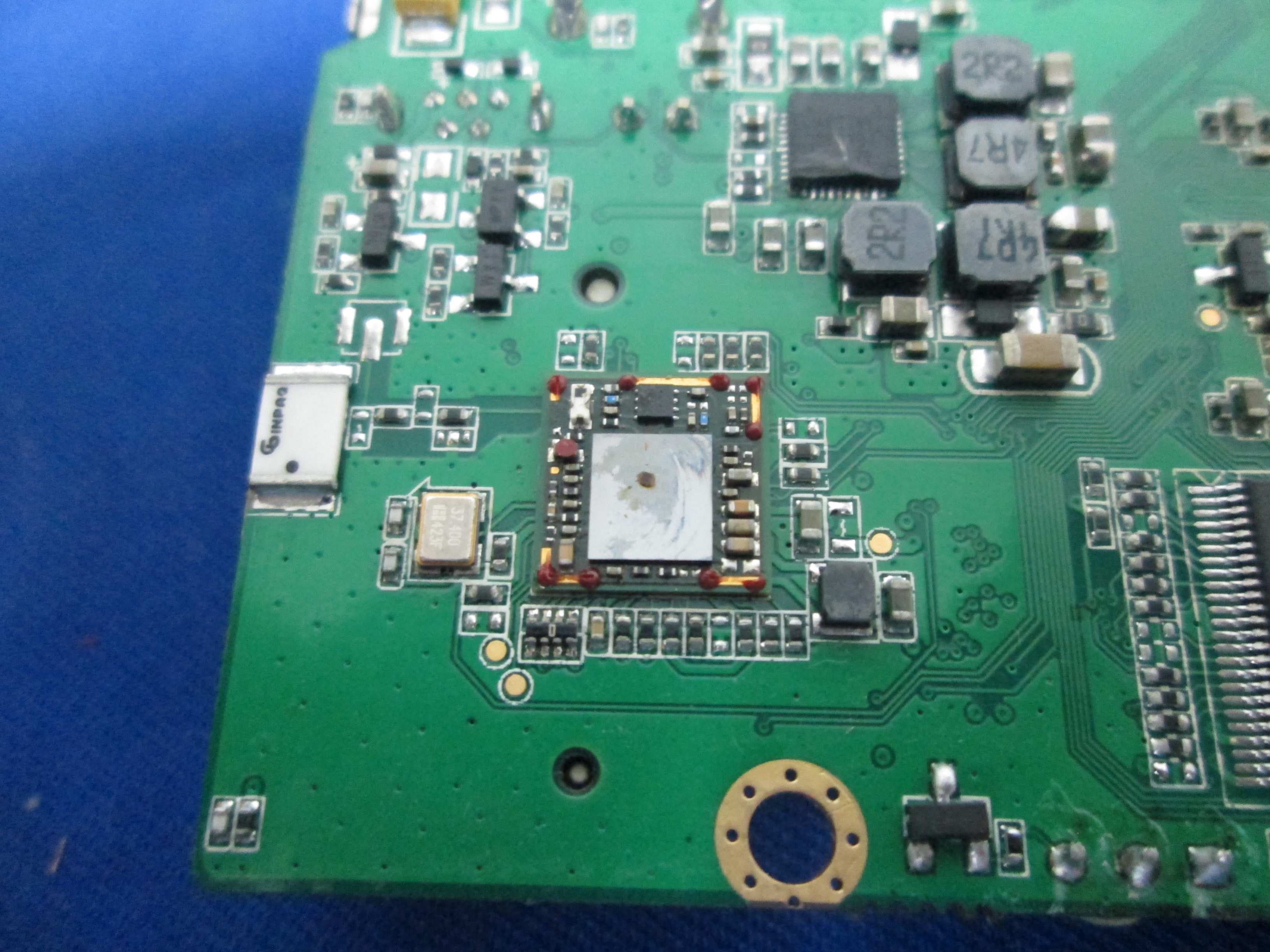
X280073
Jan 20, 2015MIPS Creator CI20 platform
Equipment Class
DTS - Digital Transmission System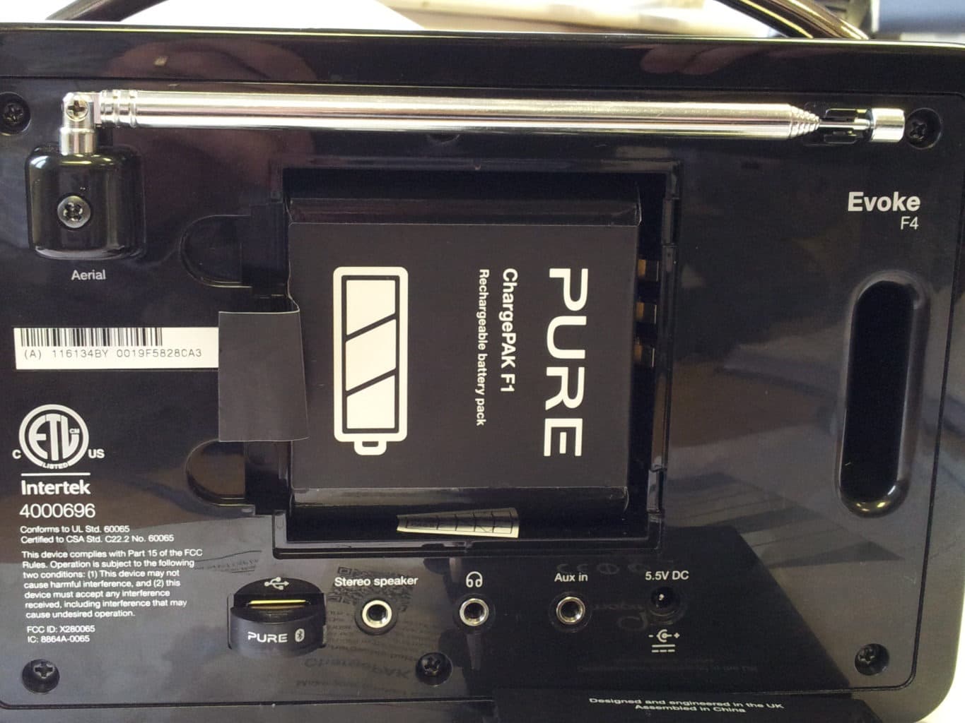
X280065
Feb 02, 2014Evoke F4
Equipment Class
DTS - Digital Transmission System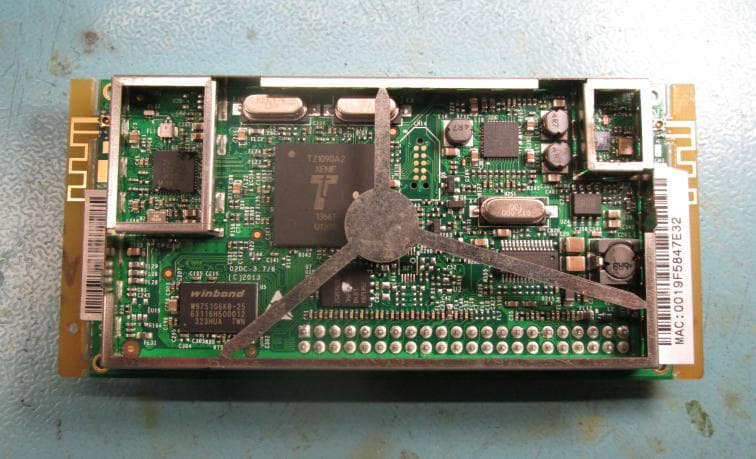
X280072
Feb 02, 2014Cougar Module Type A
Equipment Class
DSS - Part 15 Spread Spectrum Transmitter
X280067
Aug 11, 2013Jongo T6
Equipment Class
DTS - Digital Transmission System
X280070
Aug 03, 2013Jongo T2
Equipment Class
DTS - Digital Transmission System