X4K-WPTX5V102Premium Wall Control
Automatic Technology (Australia) Pty. Ltd.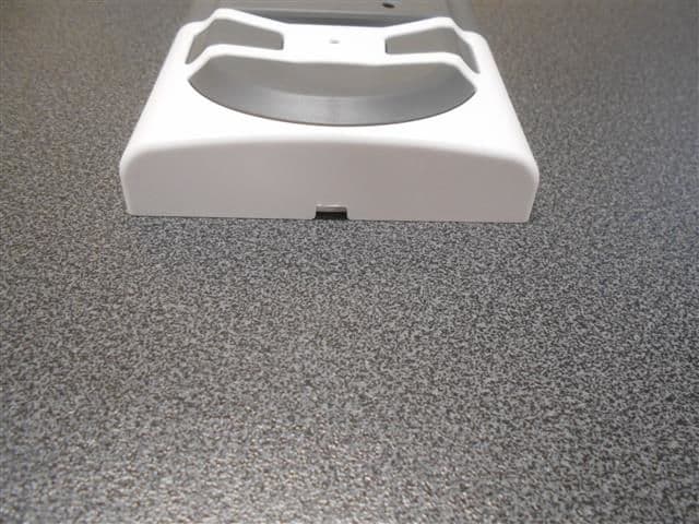
Click to zoom
Application Details
- Equipment Class
- DSC - Part 15 Security/Remote Control Transmitter
- Date of Grant
- Feb 07, 2021
- Application Purpose
- Original Equipment
- Date of Application
- Feb 07, 2021
- Equipment Note
- Premium Wall Control
- Frequency Range
- 433.47000000 - 434.37000000
- Country
- Australia
Documents & Files
Document Text
Text extracted from the exhibit documents filed with the FCC. Open a document above to read the original.
Users Manual
FOR RESIDENTIAL USE ONLY Dominator Tempo & Syncro Instruction Manual Overhead Garage Door Operator 4008033 Conforms to: ANSI/CAN/UL325 Tested to comply with Part 15 of the FCC Rules Doc # 160416_00 Part # 87406 Released 08/09/20 SYNCRO ATS-3 DOMINATOR TEMPO ATS-2AM SECTIONAL DOOR OPENER SYNCRO ATS-3 DOMINATOR SYNCRO ATS-3AM SMART SECTIONAL DOOR OPENER WARNING!: It is vital for the safety of persons to follow all instructions. Failure to comply with the installation instructions and the safety warnings may result in serious personal injury and/or property and remote control opener damage. Please save these instructions for future reference. ELECTROCUTION!: To reduce the risk of electric shock, this equipment has a grounding type plug that has a third (grounding) pin. This plug will only fit into a grounding type outlet. If the plug does not fit into the outlet, contact a qualified electrician to install the proper outlet. Do not change the plug in any way. This operator is not equipped for permanent wiring. Contact a qualified electrician to install a suitable receptacle if one is not available. Diamond PD Power Drive : Instruction Manual Dominator Tempo & Syncro Instruction Manual ATS-3AM & ATS-2AM 3 © Copyright 2019 CONTENTS Overhead Garage Door Operator 1. Safety Information 4 2. System Specifications 5 3. Operating controls 6 4. Kit Contents 7 5. Operator Safety & Security 8 5.1 Manual Door Operation 8 5.2 Emergency Evacuations 8 5.3 Power Failure 8 5.4 Re-Engaging the Operator 8 5.5 Security - Inbuilt Locking Facility 8 6. Installation Instructions 9 6.1 C-Rail Assembly 10 6.2 Mounting Operator for a Track Type Door 10 6.2.1 Determine Bracket Position 10 6.2.2 Mounting the Wall Bracket 10 6.2.3 Attach the C-Rail to the Wall Bracket 10 6.2.4 Securing the Powerhead Perforated Angle or equivalent 11 6.2.6 Mounting Door Bracket 11 6.2.7 Attaching the Arms 11 6.3 Safety Beam Installation 12 6.3.1 Safety Infra-Red Beam Kit (P/N 62047) 12 6.3.2 Assembling the Mounting Bracket 12 6.3.3 PE Assist Alignment 12 6.4 Setting Speed and Limits 13 6.4.1 Set the Limit Positions and adjust drive speed: 13 6.4.2 Clearing the Door Limit Positions 13 6.4.3 Re-profiling the Door 13 6.5 Safety Testing & Auto-Close 14 6.5.1 Obstruction Detection Test 14 6.5.2 Test the Close Cycle and Safety Reversal 14 6.5.3 Testing the Open Cycle 14 6.5.4 Test the Manual Door Operation 14 6.5.5 Auto-Close 14 6.6 Coding Transmitters 15 6.6.1 Setting Remote Control Transmitter Codes 15 6.6.2 Install Wireless Wall Mounted Remote Transmitter 16 6.6.5 Remotely Coding Remote Control Transmitters 16 6.6.3 Erasing All Remote Control Transmitter Codes 16 6.6.4 Vacation Mode 16 6.7 Battery Backup 17 6.7.1 Connecting the Battery Backup 17 6.7.2 Test the Opener 17 6.7.3 LED Battery indicator 17 6.8 Accessories 17 6.9 Auto-Ki Smart Phone Control 18 7. Operation Instructions 19 7.1 How to Use Your Operator 20 7.1.1 To Operate the opener: 20 7.1.2 Replacing the Battery: 3V Lithium Battery CR2032. 20 7.2 User Operating Controls 21 7.3. Troubleshooting 22 7.4. Service / Warning Indicator 23 7.4.1 Main Light = Service / Warning Indicator: 23 7.4.2 Connecting or Disconnecting Accessories: 23 8. User Maintenance Instruction 23 8.1 Door Maintenance 23 8.2 If You Need a Service Call 23 9. Appendix 24 A - Status Indication during Operating Mode. 24 B - Adjustment Mode Instructions 25 C - Adjusting Force Margins 25 D - Battery Functions 25 E - Setting limits via Transmitter 26 F - Setting the PET Mode position 27 G - Setting up Tilt Door 27 4 ATS-3AM & ATS-2AM Dominator Tempo & Syncro Instruction Manual 1. Safety Information Please read these important safety rules These safety alert symbols indicate a personal safety or property damage instruction exists. READ THESE INSTRUCTIONS CAREFULLY. This automatic garage door operator is designed and tested to offer safe service provided it is installed and operated in strict accordance with the following safety rules. Failure to comply with the installation instructions and the safety warnings may result in death, serious personal injury and/or property damage. WARNING! •This operator should be installed in accordance with relevant US and Canada Standards. •To reduce the risk of injury to persons – Use this operator only with a sectional door. DO NOT install product on J-Type or Single Piece Doors. •This operator is not suitable for commercial, industrial or common entry applications. •This operator is a plug in domestic appliance and is designed for indoor use only. It must be installed in a dry position that is protected from the weather. •Door must have Safety Beams fitted. •Activate the operator only when the garage door is in full view, free of obstructions and with the operator properly adjusted. •The network device allows for operation of the door when not in line- of-sight of the door and operator. Therefore the door may operate unexpectedly, therefore do not allow anything to stay in or near the path of the door. •Watch the moving door and keep people away until the door is completely opened or closed. ELECTROCUTION: •Installation and wiring must be in compliance with your local building and electrical codes. •This operator is not equipped for permanent wiring. Contact a qualified electrician to install a suitable receptacle if one is not available. •To reduce the risk of electric shock, this equipment has a grounding type plug that has a third (grounding) pin. This plug will only fit into a grounding type outlet. If the plug does not fit into outlet, contact a qualified electrician to install the proper outlet. Do not change the plug in any way. •If the power cord is damaged, it must be replaced by the manufacturer, its service agent or a similarly qualified person in order to avoid a hazard. •Connect the power cord only to properly earthed mains. If an extension lead must be used, make sure it is a 3-core lead and approved to 7 amp capacity. •This unit is not user serviceable. Unplug the power…
Text truncated - open the document above for the full version.
Cover Letter(s)
14 January 2021 Federal Communications Commission Authorization and Evaluation Division Confidentiality Request regarding application for certification of FCC ID: X4K-WPTX5V102. Pursuant to Sections 0.457 and 0.459 of the Commission’s Rules, we hereby request confidential treatment of information accompanying this application as outlined below: Exhibit Type File Name Block Diagram CONF_WTX-7V1AM_Blkdia.pdf Schematics CONF_WTX-7V1AM_Schem.pdf Operational Description CONF_WTX-7V1AM_OpDes.pdf The above materials contain trade secrets and proprietary information not customarily released to the public. The public disclosure of these materials may be harmful to the applicant and provide unjustified benefits to its competitors. The applicant understands that pursuant to Section 0.457 of the Rules, disclosure of this application and all accompanying documentation will not be made before the date of the Grant for this application. Sincerely, Nikolai Klepikov Senior Electronics Design Engineer
Cover Letter(s)
EMC Technologies Pty Ltd, 176 Harrick Road, Keilor Park VIC 3042 Australia www.emctech.com.au To: Federal Communications Commission Attention: Certification Officer Date: February 3, 2021 EMC Ref: M2012022 Subject: FCC FILING – ORIGINAL CERTIFICATION - FCC ID: X4K-WPTX5V102 Company: Automatic Technology (Australia) Pty Ltd FCC ID: FCC ID: X4K- X4K-WPTX5V102 EUT: Premium Wall Control Test Firm: EMC Bayswater Pty Ltd (Accredited Test Site Designation No. A0004) Automatic Technology (Australia) Pty Ltd is applying for FCC Certification of the Premium Wall Control (Wall Mounted Remote Control – Model WTX-7V1AM). The device is a wall mounted transmitter used to control (open and close) Garage door openers, Gate openers and other ATA equipment which require remote operations. The device is sold as part of the Dominator range of garage door operators therefore the supplied user manual includes a section specific to this transmitter (Refer to supplied user manual exhibit: 160416_00 Dominator ATS Series Instruction Manual - page 16 for device details and page 15 for FCC and ISED Canada regulatory compliance statements). Testing was performed in accordance with the requirements of FCC 15C, Section 15.231. EMC Technologies Pty Ltd is acting as agent for Automatic Technology (Australia) Pty Ltd in this application. Best Regards _____________ Chris Zombolas Technical Director EMC Technologies Pty Ltd 176 Harrick Road, Keilor Park, VIC 3042 Australia Ph. +61 3 9365 1000; www.emctech.com.au EMC Technologies Pty Ltd ABN 82 057 105 549 176 Harrick Road, Keilor Park, VIC 3042 Australia Ph: + 613 9365 1000 Fax: + 613 9331 7455 Email: [email protected]
Cover Letter(s)
Federal Communications Commission Authorization and Evaluation Division 1435 Oakland Mills Road Columbia, MD 21046 Date: 14 January 2021 SUBJECT: FCC Application for FCC ID: X4K-WPTX5V102 To Whom It May Concern: We, the undersigned, hereby authorize Chris Zombolas at EMC Technologies Pty Ltd on our behalf, to apply to the Federal Communications Commission on our equipment. Any and all acts carried out by Chris Zombolas on our behalf shall have the same effect as acts of our own. This is to advise that we are in full compliance with the Anti- Drug Abuse Act. We, the applicant, are not subject to a denial of federal benefits pursuant to Section 5301 of the Anti-Drug Act of 1988, 21 USC853a, and no party to the application is subject to a denial of federal benefits pursuant to that section. Regards, Nikolai Klepikov Senior Electronics Design Engineer
External Photos
Page 1 of 3 EMC ENGINEERS & LABORATORIES EMC Bayswater Pty Ltd 18/88 Merrindale Drive Croydon South, Victoria, 3136, Australia Telephone: +61 3 9761 5888 Facsimile: +61 3 8761 6547 Email: [email protected] ABN: 49 112 221 333 Photograph Annex A: External - EUT Photographs Automatic Technology Australia Pty. Ltd. WTX-7V1AM Wall Mounted Remote Control REPORT: E2012-1366-1 Annex A DATE: December, 2020 EMC Bayswater Test Report E2012-1366-1 Annex A Page 2 of 3 This document may not be reproduced, except in full, without written approval from EMC Bayswater Pty Ltd. Photographs Number Photograph Description 1 EUT – External Views 2 3 4 5 6 EMC Bayswater Test Report E2012-1366-1 Annex A Page 3 of 3 This document may not be reproduced, except in full, without written approval from EMC Bayswater Pty Ltd. Photograph 1 Photograph 2 Photograph 3 Photograph 4 Photograph 5 Photograph 6
ID Label/Location Info
Automatic Technology Australia Pty Ltd. Model WTX-7V1AM This device complies with Part 15 of the FCC Rules. Operation is subject to the following two conditions: (1) this device may not cause harmful interference, and (2) this device must accept any interference that may cause undesired operation. FCC ID: X4K-WPTX5V102 IC: 8880A-WPTX5V102 Made in China 4 32 1 D B A C ECO. 6-8 FIVEWAYS BOULEVARD, KEYSBOROUGH, VIC, 3173, AUSTRALIA PHONE: +61(0) 3 9791 0200 FAX: +61(0) 3 9791 0250 WEB: www.automatictechnology.com.au NAME Automatic Technology Australia Pty Ltd. DATE G.GAFF 1 : 1 REMARKS MAT'L 1 QTY PROPRIETARY AND CONFIDENTIAL DESCRIPTION DWG NO. ITEM DEBUR AND BREAK SHARP EDGES RADIUS: 0.5 CHAMFER: 0.5 x 45 SURFACE FINISH DECIMAL: 0.X 0.1 0.XX 0.05 ANGLE: 0.5 GENERAL TOLERANCES: THE INFORMATION CONTAINED IN THIS DRAWING IS THE SOLE PROPERTY OF AUTOMATIC TECHNOLOGY AUSTRALIA Pty Ltd. ANY REPRODUCTION IN PART OR AS A WHOLE WITHOUT THE WRITTEN PERMISSION OF AUTOMATIC TECHNOLOGY AUSTRALIA Pty Ltd. IS PROHIBITED. TITLE: HOUSING WTX-7AM WT SP SCALE: PART NO. 160349_02 REV.SHEET 86835 A4H DRAWING NO. 18/01/21 ALL TEXT TO BE BLACK UNLESS OTHERWISE STATED, BACKGROUND WHITE. 36 25 56.4 42
Internal Photos
Page 1 of 5 EMC ENGINEERS & LABORATORIES EMC Bayswater Pty Ltd 18/88 Merrindale Drive Croydon South, Victoria, 3136, Australia Telephone: +61 3 9761 5888 Facsimile: +61 3 8761 6547 Email: [email protected] ABN: 49 112 221 333 Photograph Annex B: Internal - EUT Photographs Automatic Technology Australia Pty. Ltd. WTX-7V1AM Wall Mounted Remote Control REPORT: E2012-1366-1 Annex B DATE: December, 2020 EMC Bayswater Test Report E2012-1366-1 Annex B Page 2 of 5 This document may not be reproduced, except in full, without written approval from EMC Bayswater Pty Ltd. Photographs Number Photograph Description 1 EUT – Internal Views 2 3 4 5 6 7 8 9 10 11 12 13 Transmitter battery EMC Bayswater Test Report E2012-1366-1 Annex B Page 3 of 5 This document may not be reproduced, except in full, without written approval from EMC Bayswater Pty Ltd. Photograph 1 Photograph 2 Photograph 3 Photograph 4 Photograph 5 Photograph 6 EMC Bayswater Test Report E2012-1366-1 Annex B Page 4 of 5 This document may not be reproduced, except in full, without written approval from EMC Bayswater Pty Ltd. Photograph 7 Photograph 8 Photograph 9 Photograph 10 Photograph 11 Photograph 12 EMC Bayswater Test Report E2012-1366-1 Annex B Page 5 of 5 This document may not be reproduced, except in full, without written approval from EMC Bayswater Pty Ltd. Photograph 13
Test Report
Page 1 of 35 EMC ENGINEERS & LABORATORIES EMC Bayswater Pty Ltd 18/88 Merrindale Drive Croydon South, Victoria, 3136, Australia Telephone: +61 3 9761 5888 Facsimile: +61 3 8761 6547 Email: [email protected] ABN: 49 112 221 333 RADIO CERTIFICATION REPORT In accordance with: CFR47 FCC Part 15, Subpart C – Section 15.231 Automatic Technology Australia Pty. Ltd. WTX-7V1AM Wall Mounted Remote Control FCC ID: X4K-WPTX5V102 REPORT: E2012-1366-1 DATE: January, 2021 Accreditation Number: 18553 Accredited for compliance with ISO/IEC 17025 The results of the tests, calibrations and/or measurements included in this document are traceable to Australian/national standards. NATA is a signatory to the ILAC Mutual Recognition Arrangement for the mutual recognition of the equivalence of testing and calibration reports. This document may not be reproduced except in full without approval from EMC Bayswater, with the exception of the certificate on page 2. EMC Bayswater Test Report E2012-1366-1 Page 2 of 35 Prepared & tested by: Approved by: 25/01/2021 10:40 Adnan Zaman (EMC Test Engineer) Neville Liyanapatabendige (Manager) Date Accreditation number: 18553. The results of the tests, calibrations and/or measurements included in this document are traceable to Australian/national standards. NATA is a signatory to the ILAC Mutual Recognition Arrangement for the mutual recognition of the equivalence of testing, calibration and inspection reports. This document may not be reproduced except in full without approval from EMC Bayswater, with the exception of the certificate on page 2. Certificate of Compliance EMC Bayswater Test Report: E2012-1366-1 Issue Date: January, 2021 Product(s): Wall Mounted Remote Control Model No: WTX-7V1AM Serial No: Not stated Variant: Not stated FCC ID: X4K-WPTX5V102 Client Details: Mr. Nikolai Klepikov Automatic Technology Australia Pty. Ltd. 6 – 8 Fiveways Boulevard Keysborough Victoria 3173 Australia Phone No: +61 3 9791 0275 Fax No: +61 3 9791 0250 e-mail: [email protected] Test Specification: CFR47 FCC Part 15, Subpart C – Section 15.231 Results Summary: FCC 15.203 - Antenna Requirement Complied FCC 15.231(a) - Transmitter Deactivation Complied FCC 15.231(b) - Field strength of fundamental Complied FCC 15.231(b), 15.209 - Field strength of spurious emissions Complied FCC 15.231(c) - Emission Bandwidth Complied Test Date(s): 1 st to 3 rd of December, 2020 Test House (Issued By): EMC Bayswater Pty Ltd 18/88 Merrindale Drive Croydon South Victoria 3136 Australia FCC Accredited Test Firm Registration number: 527798 FCC Accredited Test Firm Designation number: AU0004 Phone No: +61 3 9761 5888 e-mail: [email protected] Fax No: +61 3 8761 6547 Web: www.emcbayswater.com.au This is to certify that the necessary measurements were made by EMC Bayswater Pty Ltd, and that the Automatic Technology Australia Pty. Ltd., WTX-7V1AM, Wall Mounted Remote Control, has been tested in accordance with requirements contained in the appropriate commission regulations. EMC Bayswater Test Report E2012-1366-1 Page 3 of 35 Accreditation number: 18553. The results of the tests, calibrations and/or measurements included in this document are traceable to Australian/national standards. NATA is a signatory to the ILAC Mutual Recognition Arrangement for the mutual recognition of the equivalence of testing, calibration and inspection reports. This document may not be reproduced except in full without approval from EMC Bayswater, with the exception of the certificate on page 2. Radio Certification Report for Automatic Technology Australia Pty. Ltd. Contents 1. Introduction ................................................................................................................... 4 2. Test Report Revision History ........................................................................................ 4 3. Report Information ........................................................................................................ 4 4. Summary of Results ...................................................................................................... 4 5. Product Sample, Configuration & Modifications ......................................................... 5 5.1. Product Sample Details ............................................................................................ 5 5.2. Product description ................................................................................................... 5 5.3. Support Equipment ................................................................................................... 6 5.4. Product operating modes .......................................................................................... 6 5.5. Product operating mode for testing ........................................................................... 6 5.6. Configuration ............................................................................................................ 6 5.7. Modifications ............................................................................................................. 6 5.8. Test Facility .............................................................................................................. 6 5.9. Test Equipment ........................................................................................................ 6 6. Referenced Standards ................................................................................................... 7 7. Referenced Documents ................................................................................................. 7 8. Antenna Requirement – FCC Part 15.203 ..................................................................... 8 8.1. Requirements ........................................................................................................... 8 8.2. Result .....................................................................................................................…
Text truncated - open the document above for the full version.
Test Setup Photos
Page 1 of 4 EMC ENGINEERS & LABORATORIES EMC Bayswater Pty Ltd 18/88 Merrindale Drive Croydon South, Victoria, 3136, Australia Telephone: +61 3 9761 5888 Facsimile: +61 3 8761 6547 Email: [email protected] ABN: 49 112 221 333 Photograph Annex C: Test Configuration Photographs Automatic Technology Australia Pty. Ltd. WTX-7V1AM Wall Mounted Remote Control REPORT: E2012-1366-1 Annex C DATE: December, 2020 EMC Bayswater Test Report E2012-1366-1 Annex C Page 2 of 4 This document may not be reproduced, except in full, without written approval from EMC Bayswater Pty Ltd. Photographs Number Photograph Description 1 EUT X orientation 2 EUT Z orientation 3 Field strength of fundamental, Duty cycle and Emission Bandwidth – Test configuration Field strength of spurious emissions – Test configuration – 30MHz to 1GHz 4 5 Field strength of spurious emissions – Test configuration – 9kHz to 30MHz 6 7 8 Field strength of spurious emissions – Test configuration – 1GHz to 4.5GHz 9 EMC Bayswater Test Report E2012-1366-1 Annex C Page 3 of 4 This document may not be reproduced, except in full, without written approval from EMC Bayswater Pty Ltd. Photograph 1 Photograph 2 Photograph 3 Photograph 4 Photograph 5 Photograph 6 EMC Bayswater Test Report E2012-1366-1 Annex C Page 4 of 4 This document may not be reproduced, except in full, without written approval from EMC Bayswater Pty Ltd. Photograph 7 Photograph 8 Photograph 9
Contact Information
Applicant
Nikolai Klepikov(Mr.)
Test Firm
EMC Technologies Pty. Ltd.Shabbir Ahmed
Technical Specifications
| # | Rule Parts | Frequency Range | Power Output |
|---|---|---|---|
| 1 | 15.231 | 433.47 MHz - 434.37 MHz | - |
Other Applications from Automatic Technology (Australia) Pty. Ltd.
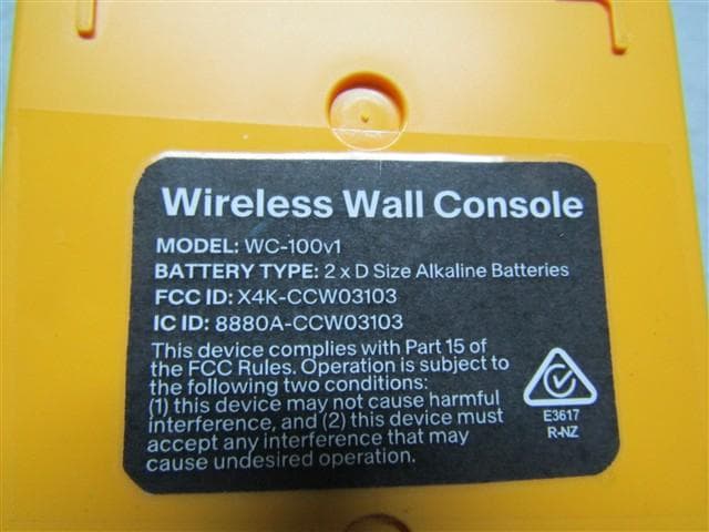
X4K-CCW03103
Apr 02, 2026Wall-mounted wireless transmitter (wall console).
Equipment Class
DSC - Part 15 Security/Remote Control Transmitter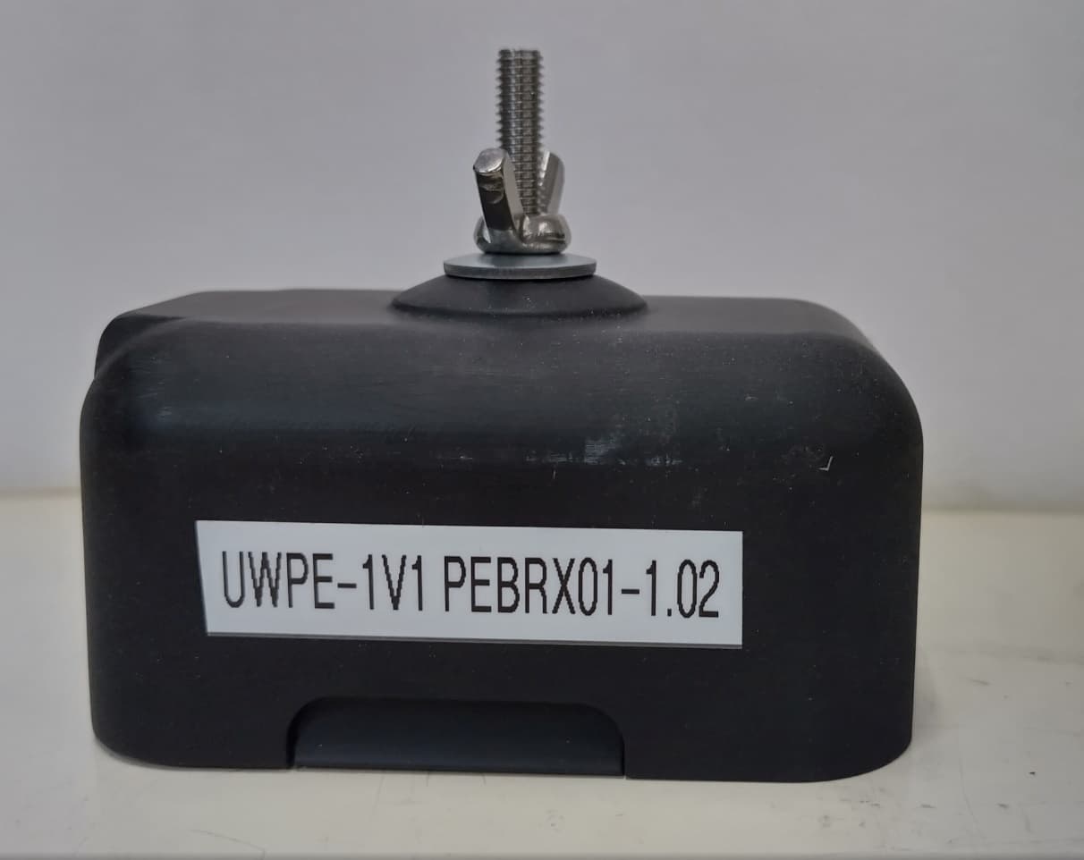
X4K-UWPEB01
Mar 12, 2026Universal PE (Photo Electric) Beam Kit - PE Beam Transmitter
Equipment Class
DTS - Digital Transmission System
X4K-ABS02200
Mar 05, 2026Universal PE (Photo Electric) Beam Kit - Base Station
Equipment Class
DTS - Digital Transmission System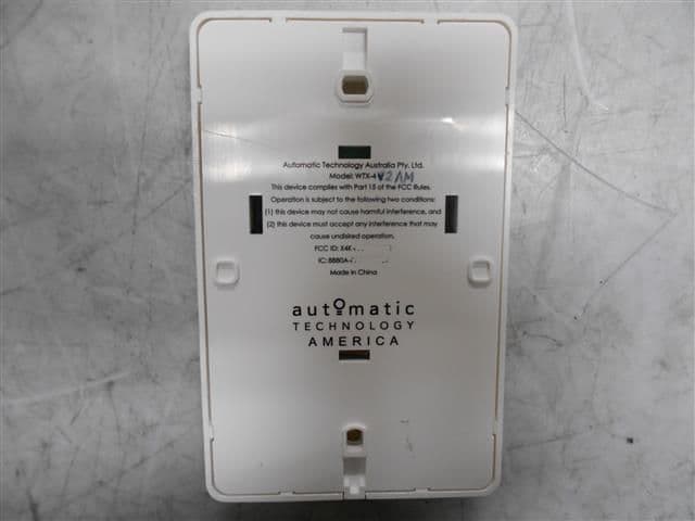
X4K-WPTX5V102B
Mar 02, 2021Wall Control
Equipment Class
DSC - Part 15 Security/Remote Control Transmitter