X55AX1-UStage Luminaires
Astera LED Technology GmbH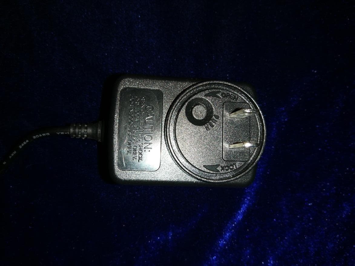
Click to zoom
Application Details
- Equipment Class
- DSS - Part 15 Spread Spectrum Transmitter
- Date of Grant
- Jan 06, 2020
- Application Purpose
- Original Equipment
- Date of Application
- Jan 06, 2020
- Equipment Note
- Stage Luminaires
- Frequency Range
- 917.00000000 - 922.20000000
- Company
- Astera LED Technology GmbH
- Country
- Germany
Documents & Files
Document Text
Text extracted from the exhibit documents filed with the FCC. Open a document above to read the original.
Users Manual
AX1 PIXELTUBE™ User Manual Astera LED Technology GmbH User Manual for AX1 Pixeltube™ 2018-08-29 Page | 1 1 CONTENTS 2 Package Contents ............................................................................................................................................... 3 3 Safety and Handling ............................................................................................................................................. 3 4 Safety and Handling ............................................................................................................................................. 4 4.1 Mounting Options ......................................................................................................................................... 6 4.2 Battery ............................................................................................................................................................ 7 4.3 Charging ........................................................................................................................................................ 7 4.4 AC Wiring ....................................................................................................................................................... 7 5 Specification .......................................................................................................................................................... 8 6 Troubleshooting ..................................................................................................................................................... 8 7 Operation ............................................................................................................................................................... 9 7.1 AsteraRGB Color Space .............................................................................................................................. 9 7.2 Ways to Control .......................................................................................................................................... 10 7.3 Control By Infrared with ARC1 .................................................................................................................. 10 7.4 Control by the AsteraApp™ ..................................................................................................................... 11 7.5 Control by Wireless DMX ............................................................................................................................ 11 7.6 Button ............................................................................................................................................................ 12 7.7 Status Display ............................................................................................................................................... 12 7.8 Blue Mode / Show Static Color ................................................................................................................ 14 7.9 Tap the Light (for AsteraApp™) ............................................................................................................... 14 7.10 DMX Addressingvia Button ........................................................................................................................ 15 8 Using the Light with the AsteraApp™ .............................................................................................................. 16 8.1 Pair your Light with the AsteraApp™ ...................................................................................................... 16 8.2 Powerful Light Control ................................................................................................................................ 17 8.3 Change the Color ...................................................................................................................................... 17 8.4 Create a Set ................................................................................................................................................ 18 8.5 Targeting Lights ........................................................................................................................................... 19 8.6 Changing The Effect .................................................................................................................................. 20 8.7 List of Effects ................................................................................................................................................ 21 8.8 Chaser Effects in Deep .............................................................................................................................. 22 8.9 The Main Screen ......................................................................................................................................... 23 8.10 Brightness ...................................................................................................................................................... 24 8.11 RUNTIME ........................................................................................................................................................ 24 8.12 Theft Alarm ................................................................................................................................................... 25 8.13 Anti-Flicker .................................................................................................................................................... 26 8.14 Enter and Leave Standby ......................................................................................................................... 27 8.15 DMX Settings ................................................................................................................................................ 28 8.16 Dimmer Curve ...............................…
Text truncated - open the document above for the full version.
Cover Letter(s)
Astera LED-Technology GmbH Office of Engineering Technology Federal Communications Commission 7435 Oakland Mills Road Columbia, MD21046 Date: 12-17-2019 Subject; Request for Long Term Confidentiality FCC ID: X55AX1-U To Whom It May Concern, Pursuant to the provisions of the Commission’s rules Title 47 Sections §0.457 and §0.459, we are requesting the Commission to withhold the following attachment(s) as confidential documents from public disclosure indefinitely. These documents contain detailed system and equipment descriptions and are considered as proprietary information in operation of the equipment. The public disclosure of these documents might be harmful to our company and would give competitors an unfair advantage in the market. Schematic Diagram Block Diagram Operational Description It is our understanding that all measurement test reports, FCC ID label format and correspondence during the certification review process cannot be granted as confidential documents and this information will be available for public review once the grant of equipment authorization is issued. Sincerely, Signature: Name: Norbert Ernst Title: General Manager
Cover Letter(s)
Astera LED-Technology GmbH Letter of Authorization Company: Astera LED-Technology GmbH Address: Stahlgruberring 36, 81829 Munich, Germany Product Name: Stage Luminaires Model Number(s): AX1-U Product Description: Stage Luminaires We authorize MiCOM Labs Inc., 575 Boulder Court, Pleasanton, California 94566, USA, to act on our behalf on all matters concerning the certification of above named equipment. We declare that MiCOM Labs Inc. is allowed to forward all information related to the approval and certification of equipment to the regulatory agencies as required and to discuss any issues concerning the approval application. Any and all acts carried out by MiCOM Labs on our behalf shall have the same effect as acts of our own. Signature: Date: 2019-12-17 Name: Norbert Ernst Title: General Manager Company: Astera LED-Technology GmbH
External Photos
Page 1 of 4 External Picture Page 2 of 4 Page 3 of 4 adaptor adaptor Page 4 of 4 adaptor
ID Label/Location Info
Model No.: AX1-U Label location
Internal Photos
Page 1 of 11 Internal Picture Page 2 of 11 Page 3 of 11 Page 4 of 11 Page 5 of 11 Page 6 of 11 Page 7 of 11 Page 8 of 11 Page 9 of 11 Page 10 of 11 adaptor adaptor Page 11 of 11 adaptor
RF Exposure Info
FCC ID: X55AX1-U RF Exposure Evaluation Limits The criteria listed in the following table shall be used to evaluate the environment impact of human exposure to radio frequency (RF) radiation as specified in 1.1307(b) Limits for Maximum Permissible Exposure (MPE) Frequency range (MHz) Electric field strength (V/m) Magnetic field strength (A/m) Power density (mW/cm 2 ) Averaging time (minutes) (A) Limits for Occupational/Controlled Exposures 0.3–3.0 614 1.63 *(100) 6 3.0–30 1842/f 4.89/f *(900/f 2 ) 6 30–300 61.4 0.163 1.0 6 300–1500 f/300 6 1500–100,000 5 6 (B) Limits for General Population/Uncontrolled Exposure 0.3–1.34 614 1.63 *(100) 30 1.34–30 824/f 2.19/f *(180/f 2 ) 30 30–300 27.5 0.073 0.2 30 300–1500 f/1500 30 1500–100,000 1.0 30 f = frequency in MHz Friis transmission formula: Pd = (Pout*G)/(4*pi*r 2 ) Where Pd = power density in mW/cm 2 , Pout = output power to antenna in mW; G = gain of antenna in linear scale, Pi = 3.1416; R = distance between observation point and center of the radiator in cm Pd id the limit of MPE, 1 mW/cm 2 . If we know the maximum gain of the antenna and the total power input to the antenna, through the calculation, we will know the distance r where the MPE limit is reached. Test Procedure Software provided by client enabled the EUT to transmit and receive data at lowest, middle and highest channel individually. Test Result of RF Exposure Evaluation Channel Output power (mW) Power Density at R=20cm (mW/cm 2 ) Limit (mW/cm 2 ) Result Lowest 7.73 0.00243 1.0 PASS Middle 7.78 0.00245 1.0 PASS Highest 7.71 0.00242 1.0 PASS Remarks: 1. Antenna gain=2.0dBi 2. The max power density is less than MPE exempt limit, so it is compliance.
Test Report
Global United Technology Services Co., Ltd. Report No.: GTS201912000095F01 Authorized Signature: Robinson Lo Laboratory Manager This results shown in this test report refer only to the sample(s) tested, this test report cannot be reproduced, except in full, without prior written permission of the company. The report would be invalid without specific stamp of test institute and the signatures of compiler and approver. Page 1 of 53 1 Cover Page Test Report Applicant: Astera LED-Technology GmbH Address of Applicant: Stahlgruberring 36, 81829 Munich, Germany Manufacturer: Astera Manufacturing Limited Address of Manufacturer: Rm. 201, Huazhong Indutrial Park, No. 12 South Huancheng Road, Bantian Street, Longgang District, 518129 Shenzhen, China Equipment Under Test (EUT) Product Name: Stage Luminaires Model No.: AX1-U Trade Mark: ASTERA FCC ID: X55AX1-U Applicable standards: FCC CFR Title 47 Part 15 Subpart C Section 15.247 Date of sample receipt: August 05, 2019 Date of Test: August 05-October 10, 2019 Date of report issued: November 26, 2019 Test Result : PASS * * In the configuration tested, the EUT complied with the standards specified above. Report No.: GTS201912000095F01 Global United Technology Services Co., Ltd. No. 123-128, Tower A, Jinyuan Business Building, No.2, Laodong Industrial Zone, Xixiang Road, Baoan District, Shenzhen, Guangdong, China 518102 Telephone: +86 (0) 755 2779 8480 Fax: +86 (0) 755 2779 8960 Page 2 of 53 2 Version Version No. Date Description 00 November 26, 2019 Original Prepared By: Date: November 26, 2019 Project Engineer Check By: Date: November 26, 2019 Reviewer Report No.: GTS201912000095F01 Global United Technology Services Co., Ltd. No. 123-128, Tower A, Jinyuan Business Building, No.2, Laodong Industrial Zone, Xixiang Road, Baoan District, Shenzhen, Guangdong, China 518102 Telephone: +86 (0) 755 2779 8480 Fax: +86 (0) 755 2779 8960 Page 3 of 53 3 Contents Page 1 COVER PAGE .......................................................................................................................................... 1 2 VERSION .................................................................................................................................................. 2 3 CONTENTS .............................................................................................................................................. 3 4 TEST SUMMARY ..................................................................................................................................... 4 5 GENERAL INFORMATION ...................................................................................................................... 5 5.1 GENERAL DESCRIPTION OF EUT ......................................................................................................... 5 5.2 TEST MODE ........................................................................................................................................ 7 5.3 DESCRIPTION OF SUPPORT UNITS ....................................................................................................... 7 5.4 DEVIATION FROM STANDARDS ............................................................................................................. 7 5.5 ABNORMALITIES FROM STANDARD CONDITIONS .................................................................................... 7 5.6 TEST FACILITY .................................................................................................................................... 7 5.7 TEST LOCATION .................................................................................................................................. 7 6 TEST INSTRUMENTS LIST ..................................................................................................................... 8 7 TEST RESULTS AND MEASUREMENT DATA .................................................................................... 10 7.1 ANTENNA REQUIREMENT ................................................................................................................... 10 7.2 CONDUCTED EMISSIONS ................................................................................................................... 11 7.3 CONDUCTED PEAK OUTPUT POWER .................................................................................................. 14 7.4 20DB EMISSION BANDWIDTH ............................................................................................................. 16 7.5 CARRIER FREQUENCIES SEPARATION ................................................................................................ 18 7.6 HOPPING CHANNEL NUMBER ............................................................................................................. 20 7.7 DWELL TIME ..................................................................................................................................... 21 7.8 BAND EDGE ...................................................................................................................................... 25 7.9 SPURIOUS EMISSION ......................................................................................................................... 28 7.9.1 Conducted Emission Method ..................................................................................................... 28 7.9.2 Radiated Emission Method ........................................................................................................ 32 8 TEST SETUP PHOTO ............................................................................................................................ 52 9 EUT CONSTRUCTIONAL DETAILS ..................................................................................................... 53 Report No.: GTS201912000095F01 Global United Technology Services Co., Ltd. No. 123-128, Tower A, Jinyuan Business Building, No.2, Laodong Industrial Zone, Xixiang Road, Baoan District, Shenzhen…
Text truncated - open the document above for the full version.
Test Setup Photos
Radiated Emission Conducted Emission
Contact Information
Applicant
Gina Xiao(R&D Manager)
Technical Contact
Test Firm
Global United Technology Services Co. Ltd.Robinson Lo
Technical Specifications
| # | Rule Parts | Frequency Range | Power Output |
|---|---|---|---|
| 1 | 15C | 917 MHz - 922.2 MHz | 7.78 mW |
Other Applications from Astera LED Technology GmbH
X55FP7-PRPINL
Aug 27, 2024LunaBulb Preplnlay
Equipment Class
DSS - Part 15 Spread Spectrum Transmitter
X55AF250
Nov 08, 2023LeoFresnel
Equipment Class
DSS - Part 15 Spread Spectrum Transmitter
X55AX3-BTB
Sep 25, 2022LightDrop BTB
Equipment Class
DSS - Part 15 Spread Spectrum TransmitterX55FP6
Jul 25, 2022HydraPanel
Equipment Class
DSS - Part 15 Spread Spectrum Transmitter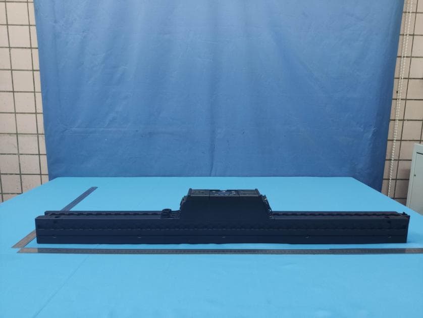
X55AX2
Jan 11, 2021Pixel Bar
Equipment Class
DSS - Part 15 Spread Spectrum Transmitter