X55AX2Pixel Bar
Astera LED Technology GmbH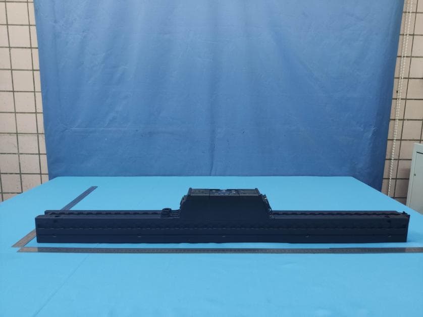
Click to zoom
Application Details
- Equipment Class
- DSS - Part 15 Spread Spectrum Transmitter
- Date of Grant
- Jan 11, 2021
- Application Purpose
- Original Equipment
- Date of Application
- Jan 04, 2021
- Equipment Note
- Pixel Bar
- Frequency Range
- 917.00000000 - 922.20000000
- Company
- Astera LED Technology GmbH
- Country
- Germany
Documents & Files
Document Text
Text extracted from the exhibit documents filed with the FCC. Open a document above to read the original.
Users Manual
Users Manual / Gebrauchsanleitung / Manuale di istruzioni / Manual de instrucciones / Manuel d‘instructions / Manual de instruções Model No: PixelBar AX2-50 / AX2-100 --- Manual Version: 1.0 --- Date of Issue: 09/17/20 // English 2-6 // Deutsch 7-11 // Italiano 12-16 // // Espanol 17-21 // Francais 22-26 // Português 27-31 // AX2 100 PIXELBAR AX2 50 PIXELBAR AX2 100 PIXELBAR AX2 50 PIXELBAR Astera LED Technology GmbH Stahlgruberring 36 81829 Munich Germany [email protected] | www.astera-led.com SAFETY INFORMATION Before you operate this unit read the manual carefully. Always make sure to include the manual if you pass/ rent/ sell the unit to another user. Keep in mind that this manual cannot address all possi- ble dangers and environments. Please use your own caution when operating. This product is for professional use only. It is not for household use. English • Do not operate the unit in areas of high temperature conditions or under direct sunlight. It will cause abnormal function or damage the product. • Always use a suitable safety wire when mounting the light overhead. • Connect the safety wire only to the intended safety mount. • Always follow local safety requirements. • Only authorized personal may service the battery. • Do not place in fire or heat. • Do not use or charge the light if it is damaged. • Avoid bumping or plunging, it may cause fire or explosion. • Never store the battery when fully drained. Always recharge immediately when empty. • Make sure to fully charge all units before storing them. • Partially charged batteries will lose capacity. • Fully recharge every 6 months if not used. • The battery may only be replaced with an original spare part from Astera. • Always charge with the flight case open. • It is recommended to charge at a temperature between 15°C and 35°C Warning: In extreme cases, abuse or misuse of standard/rechargeable batteries can lead to: • Explosion • Fire development • Heat generation or Smoke and gas development. Do not directly look into the light. • lt can cause harm to your eyes. • Do not look at the LEDs with a magnifying glass or any other optical instrument that may concentrate the light output. • Use only Astera approved accessories to diffuse or modify the light beam. The exterior surfaces of the light can become hot during normal operation. • Ensure that accidental physical contact with the device is impossible. • lnstall only in ventilated locations. • Do not cover the light. • Allow all lights to cool before touching. • Keep 0.3m (12in) from objects to be illuminated. TRANSPORTATION AND STORAGE The AX2-50/-100 PixelBar contains a Lithium Ion battery and can be carried around. A transportation case is recommended to keep the product safe. • Do not place in fire or heat. • Never store the battery when fully drained. • Make sure to fully charge all units before storing them. SECONDARY PROTECTION The AX2-50/-100 PixelBar must always be secured by a safety wire when used in a hanging position. If the primary suspension fails, the device must not fall more than 20cm. INTRODUCTION/INTENDED USE The AX2-50 / AX2-100 from ASTERA is a LED wallwasher for professional use in the event and film business. The AX2 is designed for direct or indirect illumination of objects. Due to its built-in battery it can be quickly set up and at places where traditional lights cannot be mounted easily. Like the ASTERA Tubes, the AX2 has the Titan LED Engine and offers excellent color and light values. The AX2 generates white or colored light and the color temperature can be adjusted in many ways. Both AX2 models can be controlled with the AsteraApp or with wired DMX or wireless CRMX. The device can also be controlled by the integrated display or by infrared remote control. The AX2 can be used standing or hanging. For this purpose, the device is equiped with airline tracks to attach the appropriate mounting accessories. Furthermore, several AX2 can be easily connected with the integrated BarConnect+. The AX2 can be used indoors and outdoors and has an IP65 rating. Do not shake the device. Avoid brute force when installing or operating the device. When choosing the installation-spot, please make sure that the device is not exposed to extreme heat or dust. Avoid direct sunlight for a longer period of time. There should not be any cables lying around. You endanger your own and the safety of others! The ambient temperature must be set. Keep away from direct insulation (particularly in cars) and heaters. Never use the device during thunderstorms connected to the power mains. Over voltage could destroy the device. Always disconnect the device during thunderstorms. Make sure that the area below the installation place is blocked when rigging, derigging or servicing the fixture. Always fix the fixture with an appropriate safety wire. Operate the device only after having become familiarized with its functions. Please consider that unauthorized modifications on the device are forbidden due to safety reasons! If this device will be operated in any way different to the one described in this manual, the product may suffer damages and the guarantee becomes void. Furthermore, any other operation may lead to dangers like shortcircuit, burns, electric shock, crash etc. This device is not for household use and is not suitable for permanent installation. CONTENT or #1 AX2-50 or AX2-100 PixelBar #2 Feet (2x ) #3 PowerCON TRUE1 Cable #4 Manual #1 #2 #3 #4 Use Safety rigging point. Please check the safety regulations in your region. 23 PRODUCT OVERVIEW When at top Navigation: When inside Main Menu: ON/OFF Enter Main MenuBack to previous Menu Reset SettingsScroll down Change Input SelectScroll up Set DMX AddressChoose / Confirm Color adjustment Brightness intensity and runtime control Use the menu buttons ( menu, +, - ,enter ) to navigate through the main menu. Settings for color adjustment and brightness / runti- me are directly accessible by two symbol buttons. USING THE AX2 PIXELBAR P…
Text truncated - open the document above for the full version.
Users Manual
MANUFACTURER DECLARATION Hereby, Astera LED Technology GmbH declares that the type of radio equipment PixelBar AX2-50/-100 complies with Directive 2014/53 / EU. The full text of the EU Declaration of Conformity is available at the following Internet address: https://astera-led.com/ax2 Astera LED Technology GmbH declares that this equipment has been tested and found to comply with the limits for a Class B digital device, pursuant to part 15 of the FCC rules. These limits are designed to provide reasonable protection against harmful interference in a residential installation. This equipment generates uses and can radiate radio frequency energy and, if not installed and used in accordance with the instructions, may cause harmful interference to radio communications. However, there is no guarantee that interference will not occur in a particular installation. If this equipment does cause harmful interference to radio or television reception, which can be deter-mined by turning the equipment off and on, the user is encouraged to try to correct the interference by one or more of the following measures: • Reorient or relocate the receiving antenna. • Increase the separation between the equipment and receiver. • Connect the equipment into an outlet on a circuit different from that to which the receiver is connected. • Consult the dealer or an experienced radio/TV technician for help. FCC Caution: • Any changes or modifications not expressly approved by the party responsible for compliance could void the user‘s authority to operate this equipment. • This transmitter must not be co-located or operating in conjunction with any other antenna or trans- mitter. This device complies with Part 15 of the FCC Rules. Operation is subject to the following two conditions: (1) This device may not cause harmful interference, and (2) This device must accept any interference received, including interference that may cause undesired operation. ------------------------------------------- FCC RF Radiation Exposure Statement Caution: To maintain compliance with the FCC’s RF exposure guidelines, place the product at least 20cm from nearby persons. ------------------------------------- Astera LED Technology GmbH Stahlgruberring 36 81829 Munich Germany [email protected] | www.astera-led.com DISPOSAL The light contains a lithium ion battery. • Don‘t throw the unit into the garbage at the end of its lifetime. • Make sure to dispose is according to your local ordinances and/or regulations, to avoid polluting the environment! • The packaging is recyclable and can be disposed. SICHERHEITSHINWEISE Lesen Sie vor Inbetriebnahme die Anleitung sorgfältig durch. Stellen Sie sicher, dass im Falle einer Weitergabe, eines Verleihs oder Verkaufs, die Anleitung an den Benutzer ausgehändigt wird. Seien Sie vorsichtig bei Handhabung und Betrieb dieses Gerätes. Dieses Produkt ist ausschließlich für die professionelle Nutzung vorgesehen und nicht für den Heimgebrauch. Deutsch Betreiben Sie das Gerät nicht in hoher Umgebungstemperatur oder unter direkter Son- neneinstrahlung. Das verursacht Fehlfunktionen oder Beschädigungen am Gerät. • Verwenden Sie immer ein geeignetes Sicherheitsdrahtseil, wenn Sie die Lampe hängend über Kopf montieren. • Befestigen Sie das Sicherheitsdrahtseil nur an der vorgesehenen Sicherheitsbefes- tigung. • Befolgen Sie immer die örtlichen Sicherheitsanforderungen. • Service nur durch qualifiziertes Fachpersonal. • Kein Betrieb in Feuer, in Feuernähe oder großer Hitze. • Betreiben und laden Sie die Lampe nicht bei Beschädigungen. • Vermeiden Sie Stösse und Stürze, das kann zu Feuer oder Explosionen führen. • Lagern Sie den Akku nicht, wenn er vollständig entladen ist. Laden Sie den Akku sofort nach Entladung wieder auf. • Laden Sie alle Lampen vor dem Einlagern vollständig auf. • Unvollständig geladene Akkus verlieren an Kapazität und Haltbarkeit. • Laden Sie die Akkus alle 6 Monate vollständig auf, wenn die Lampen nicht ver- wendet werden. • Der Akku darf nur durch ein Original Ersatzteil des Herstellers (Astera) ersetzt werden. • Laden Sie die Lampen nur bei geöffnetem Ladekoffer. • Empfohlen ist eine Ladung der Akkus bei einer Umgebungstemperatur zwischen 15°C und 35°C. / Warnung: In extremen Fällen kann der Missbrauch oder falsche Gebrauch von Batterien oder wiederaufladbaren Akkus zu Folgendem führen: • Explosion • Brandentwicklung • Wärmeerzeugung oder Rauch- und Gasentwicklung Sehen Sie nicht direkt in die Lichtquelle. • Das kann zu Verletzungen Ihrer Augen führen. • Betrachten Sie die LEDs nicht durch ein Vergrößerungsglas oder eine Linse, die das Licht bündeln könnte. • Verwenden Sie nur von Astera genehmigtes Zubehör, um die Lichtausgabe zu zer- streuen oder zu verändern. Die Gehäuseoberfläche der Lampe kann sich im regulären Betrieb erwärmen. • Stellen Sie sicher, dass ein versehentliches Berühren des Gehäuses ausgeschlos- sen ist. • Betrieb nur an belüfteten Standorten. • Decken Sie die Lampe nicht ab. • Lassen Sie alle Lampen vor dem Berühren abkühlen. • Halten Sie einen Sicherheitsabstand von mind. 0,3m (12 Inches) zu den zu beleuch- tenden Objekten ein. RF CHARACTERISTICS Wireless Modules EU: UHF (863-870MHz) USA: UHF (917-922.20MHz) AUS: UHF (922.30-927.50MHz) SGP: UHF (920.50-924.50MHz) Modulation FHSSFHSSFHSSFHSS ERP (Transmitter) <25mW<25mW<25mW<25mW Channel Count 47535341 Wireless Modules KOR: UHF (917.9-921.5MHz) RUS: UHF (868.75-869.12MHz) JPN: UHF (922.80-926.40MHz) CRMX (2402-2480MHz) Modulation FHSSFHSSFHSSFHSS ERP (Transmitter) <25mW<25mW<25mW<100mW Channel Count 1061979 TRANSPORT UND LAGERUNG Der AX2-50/-100 PixelBar enthält einen Lithium-Ionen-Akku und kann mitgeführt werden. Ein Transportkoffer wird empfohlen, um das Produkt sicher aufzubewahren. • Kein Betrieb oder Lagerung in Feuernähe oder bei großer Hitze. • Lagern Sie den Akku nicht, wenn er vollständig entladen ist. • Laden Sie den Akku sofort nach Entladung wieder auf. 89 SEKUNDÄRE SICHERUNG Der AX2-50/-100 PixelBar muss in hän…
Text truncated - open the document above for the full version.
Attestation Statements
Differences Declaration To whom concern, We company Astera LED-Technology GmbH hereby declares: The product models AX2-100, AX2-50 are identical in the same PCB layout, interior structure and electrical circuits, The differences are rated power(the rated power is the wattage of the bulb: AX2-100 is 96W, AX2-50 is 48W. The rated power is not effect to the RF performance, function and power), product size and model name for commercial purpose. Authorized signature: Date: 2020-12-17
Cover Letter(s)
DATE : 2020-12-17 Equipment Autorisation Division Federal Communications Commission 7435 Oakland Mills Road Columbia, MD 21046 FCC ID: X55AX2 Product Name: Pixel Bar Request for Confidentiality To Whom It May Concern, Pursuant to the provisions of the Commission’s rules Title 47 Sections §0.457 and §0.459, we are requesting the Commission to withhold the following attachment(s) as confidential documents from public disclosure indefinitely. These documents contain detailed system and equipment descriptions and are considered as proprietary information in operation of the equipment. The public disclosure of these documents might be harmful to our company and would give competitors an unfair advantage in the market. Schematic Diagram Block Diagram Operational Description In additional to above mentioned documents, in order to comply with the marketing regulations in Title 47 CFR §2.803 and the importation rules in Title 47 CFR §2.1204, while ensuring that business sensitive information remains confidential until the actual marketing of newly authorized devices, we request Short Term Confidentiality of the following attachment(s); External Photos Test Setup Photos Internal Photos User Manual For 45 days, pursuant to Public Notice DA 04-1705. OR For 180 days pursuantto KDB 726920 D01. It is our understanding that all measurement test reports, FCC ID label format and correspondence during the certification review process cannot be granted as confidential documents and this information will be available for public review once the grant of equipment authorization is issued. Signature: Name: Norbert Ernst Title: CEO Company: Astera LED-Technology GmbH
Cover Letter(s)
DATE Fed e Auth 7345 Colu On o 128, Dist r appl the d unit Co m appr For i beha for c 8182 Sign a Nam e Title: C Com p :2020-12-17 eral Commu horization & 5 Oakland M umbia, Mary our behalf, I Tower A, Jin rict, Shenzh ication for e device or sy manufactur mmission’s r roval with th instances w alf, I acknow certification, 29 Munich, G ature: e: Norbert E CEO pany: Aster 7 unications C Evaluation D Mills Road land 21046 appoint Jaso nyuan Busin en, Guang d equipment ce ystem for w red, importe regulations is applicati o where our au wledge that still resides Germany Ernst ra LED-Tec ommission Division Autho r on Wu of Glo ess Building, dong, China ertification. I which equipm ed or marke will have a on. uthorized ag all responsi with Aster a hnology Gm rity to Act a obal United T , No.2, Laod a to act as I certify that ment certific eted, as de affixed to it ent signs th ibility for com a LED-Techn mbH asAgent Technology S ong Industri our agent submitted d cation is sou efined in th a label ide he applicatio mplying with nology Gmb Services Co., ial Zone, Xixi in the pre documents p ught. I also e Federal entical to th on for certific h the terms H and Stah l , Ltd.and No iang Road, B eparation of properly des certify that Communic a hat submitte cation on ou and conditio lgruberring 3 . 123‐ Baoan f this scribe each ations ed for ur ons 36,
ID Label/Location Info
Model No.: AX2-100 Label location
RF Exposure Info
SAR evaluation MPE Calculation Method E (V/m) = (30*P*G) 0.5 /d Power Density: Pd (W/m2) = E 2 /377 E = Electric Field (V/m) P = Peak RF output Power (W) G = EUT Antenna numeric gain (numeric) d = Separation distance between radiator and human body (m) The formula can be changed to Pd = (30*P*G) / (377*d 2 ) From the peak EUT RF output power, the minimum mobile separation distance, d=0.2m, as well as the gain of the used antenna, the RF power density can be obtained. Calculated Result and Limit (WORSE CASE IS AS BELOW) Directional AntennaGain (Numeric) Peak Output Power (mW) Power Density (S)(mW/cm2) Limit of Power Density (S) (mW/cm2) Test Result 0.8(-1dBi) 9.036 (9.56dBm@919. 6MHz) 0.00144 f/1500=0.61 Compiles
Test Report
Global United Technology Services Co., Ltd. Report No.: GTS202009000128F01 Authorized Signature: Robinson Lo Laboratory Manager This results shown in this test report refer only to the sample(s) tested, this test report cannot be reproduced, except in full, without prior written permission of the company. The report would be invalid without specific stamp of test institute and the signatures of compiler and approver. Page 1 of 44 TEST REPORT Applicant: Astera LED-Technology GmbH Address of Applicant: Stahlgruberring 36, 81829 Munich, Germany Manufacturer: Astera Manufacturing Limited Address of Manufacturer: Bldg. 3, CLT Science & Technology Park, No. 7, GanLiliu Road, Jihua subdistrict, Longgang District, Shenzhen, P.C.518112 Equipment Under Test (EUT) Product Name: Pixel Bar Model No.: AX2-100, AX2-50 Trade Mark: ASTERA FCC ID: X55AX2 Applicable standards: FCC CFR Title 47 Part 15 Subpart C Section 15.247 Date of sample receipt: September 12, 2020 Date of Test: September 13, 2020-December 17, 2020 Date of report issued: December 17, 2020 Test Result : PASS * * In the configuration tested, the EUT complied with the standards specified above. Report No.: GTS202009000128F01 Global United Technology Services Co., Ltd. No. 123-128, Tower A, Jinyuan Business Building, No.2, Laodong Industrial Zone, Xixiang Road, Baoan District, Shenzhen, Guangdong, China 518102 Telephone: +86 (0) 755 2779 8480 Fax: +86 (0) 755 2779 8960 Page 2 of 44 2 Version Version No. Date Description 00 December 17, 2020 Original Prepared By: Date: December 17, 2020 Project Engineer Check By: Date: December 17, 2020 Reviewer Report No.: GTS202009000128F01 Global United Technology Services Co., Ltd. No. 123-128, Tower A, Jinyuan Business Building, No.2, Laodong Industrial Zone, Xixiang Road, Baoan District, Shenzhen, Guangdong, China 518102 Telephone: +86 (0) 755 2779 8480 Fax: +86 (0) 755 2779 8960 Page 3 of 44 3 Contents Page 1 COVER PAGE ................................................................................................................................................ 1 2 VERSION ........................................................................................................................................................ 2 3 CONTENTS .................................................................................................................................................... 3 4 TEST SUMMARY ........................................................................................................................................... 4 4.1 MEASUREMENT UNCERTAINTY .................................................................................................................. 4 5 GENERAL INFORMATION ............................................................................................................................ 5 5.1 GENERAL DESCRIPTION OF EUT ............................................................................................................... 5 5.2 TEST MODE .............................................................................................................................................. 7 5.3 TEST FACILITY .......................................................................................................................................... 7 5.4 TEST LOCATION ....................................................................................................................................... 7 5.5 DESCRIPTION OF SUPPORT UNITS ............................................................................................................. 7 5.6 DEVIATION FROM STANDARDS ................................................................................................................... 7 5.7 ABNORMALITIES FROM STANDARD CONDITIONS ......................................................................................... 7 5.8 ADDITIONAL INSTRUCTIONS ....................................................................................................................... 7 6 TEST INSTRUMENTS LIST ........................................................................................................................... 8 7 TEST RESULTS AND MEASUREMENT DATA .......................................................................................... 10 7.1 ANTENNA REQUIREMENT ......................................................................................................................... 10 7.2 CONDUCTED EMISSIONS ......................................................................................................................... 11 7.3 CONDUCTED PEAK OUTPUT POWER ........................................................................................................ 14 7.4 20DB EMISSION BANDWIDTH .................................................................................................................. 16 7.5 CARRIER FREQUENCIES SEPARATION ...................................................................................................... 18 7.6 HOPPING CHANNEL NUMBER .................................................................................................................. 20 7.7 DWELL TIME ........................................................................................................................................... 21 7.8 BAND EDGE ........................................................................................................................................... 25 7.9 SPURIOUS EMISSION ............................................................................................................................... 27 7.9.1 Conducted Emission Method ........................................................................................................... 27 7.9.2 Radiated Emission Method .............................................................................................................. 29 8 TEST SETUP PHOTO ..............…
Text truncated - open the document above for the full version.
Test Setup Photos
Radiated Emission Conducted Emission
Contact Information
Applicant
Gina Xiao(R&D Manager)
Test Firm
Global United Technology Services Co. Ltd.Robinson Lo
Technical Specifications
| # | Rule Parts | Frequency Range | Power Output |
|---|---|---|---|
| 1 | 15C | 917 MHz - 922.2 MHz | 9.04 mW |
Other Applications from Astera LED Technology GmbH
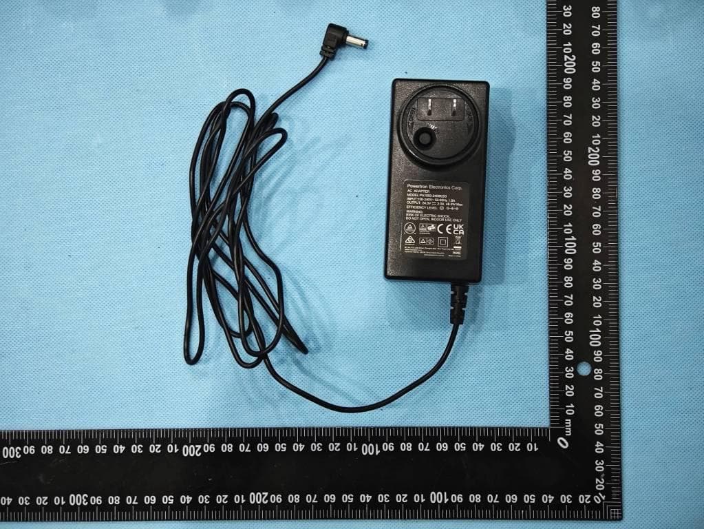
X55FP7-PRPINL
Aug 27, 2024LunaBulb Preplnlay
Equipment Class
DSS - Part 15 Spread Spectrum Transmitter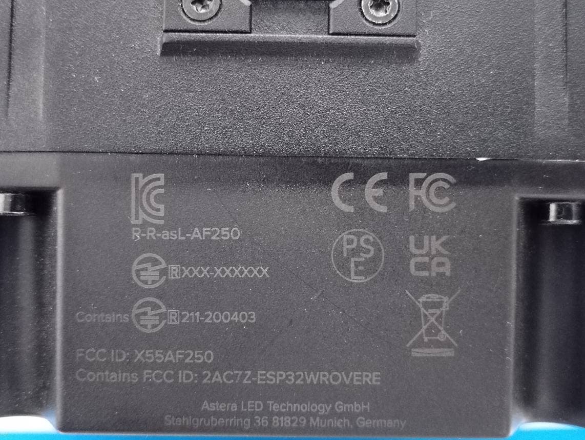
X55AF250
Nov 08, 2023LeoFresnel
Equipment Class
DSS - Part 15 Spread Spectrum Transmitter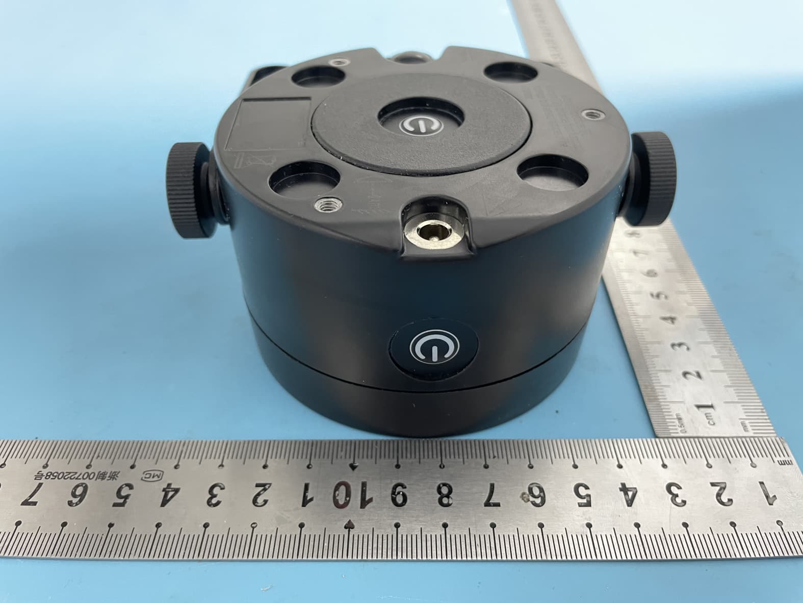
X55AX3-BTB
Sep 25, 2022LightDrop BTB
Equipment Class
DSS - Part 15 Spread Spectrum TransmitterX55FP6
Jul 25, 2022HydraPanel
Equipment Class
DSS - Part 15 Spread Spectrum Transmitter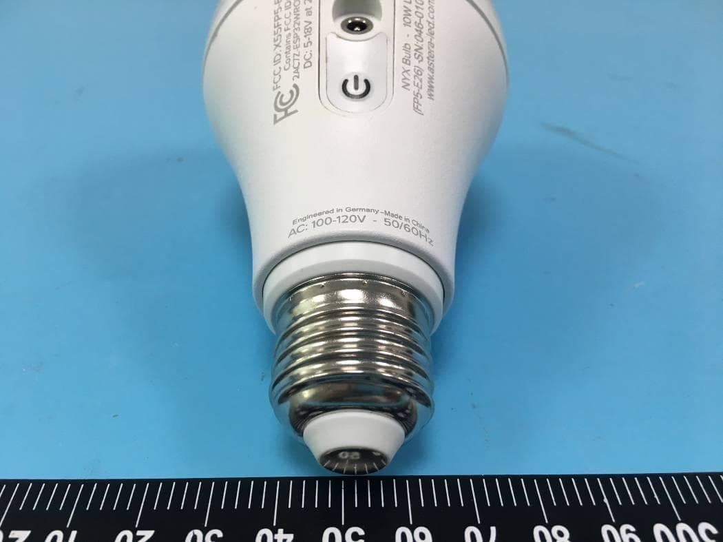
X55FP5-E26
Oct 01, 2020NYX Bulb
Equipment Class
DSS - Part 15 Spread Spectrum Transmitter