X8NA600SAmateur Radio Linear Amplifier
Array Solutions dba Array Solutions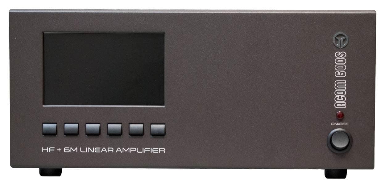
Click to zoom
Application Details
- Equipment Class
- AMP - Amplifier
- Date of Grant
- Apr 29, 2014
- Application Purpose
- Original Equipment
- Date of Application
- Mar 02, 2014
- Equipment Note
- Amateur Radio Linear Amplifier
- Frequency Range
- 1.80000000 - 54.00000000
- Country
- United States
Documents & Files
Document Text
Text extracted from the exhibit documents filed with the FCC. Open a document above to read the original.
Users Manual
Page 1 of 34 Exhibit 6: User’s Manual External Radio Frequency Power Amplifier ACOM 600S Model 600S Array Solutions 2611 North Beltline Rd Suite 109 Sunnyvale, Texas 75182 USA Tel: 214 954 7140 fax: 214 954 7142 E-mail: [email protected] Page 2 of 34 ACOM 600S HF + 6 m SOLID STATE LINEAR AMPLIFIER OPERATING MANUAL File name: Manual_ACOM600SBT_EN.doc Last edited: 18 December 2013 CONTENTS 1. GENERAL INFORMATION ......................................................................................................................... 3 1-1. Inroduction and description ....................................................................................................... 3 1-2. Owner assistance ...................................................................................................................... 3 1-3. Equipment supplied and options ............................................................................................... 3 1-4. Features .................................................................................................................................... 3 1-5. Safety considerations, explicit definitions ................................................................................. 4 2. INSTALLATION ........................................................................................................................................... 5 2-1. Unpacking and Initial Inspection ............................................................................................... 5 2-2. Amplifier location selection; cooling. ......................................................................................... 5 2-3. Connecting the amplifier within the shack ................................................................................. 6 2-4. Installing options and connecting to external devices (transceiver, computer etc) ................... 8 3. INITIAL POWER ON AND SETTING INTO OPERATION ........................................................................ 10 3-1. Low-energy (waiting) mode of the power supply .................................................................... 10 3-2. Front panel - controls and indication ....................................................................................... 10 3-3. Initial turning on – activation of the main power supply .......................................................... 11 3-4. Basic screen ............................................................................................................................ 11 3-5. Control system – buttons and menus ...................................................................................... 13 3-6. Test transmission .................................................................................................................... 13 4. OPERATION WITH THE AMPLIFIER ....................................................................................................... 17 4-1. Change of modes RX / TX and Operate / Stand-by; option AUTO OPERATE ...................... 17 4-2. Band change, standard and expanded frequency coverage .................................................. 18 4-3. Change of antennas and operation with an external antenna tuner ....................................... 19 4-4. Cooling and fans operation; modes with increased heat loading ........................................... 19 4-5. Monitoring the amplifier operating regime ............................................................................... 19 4-6. Automatic protection system ................................................................................................... 19 5. MENUS – USEFUL INSTRUMENTS AND OPTIONS .............................................................................. 21 5-1. Menu “Measurements in the amplifier” – AMP MEASURE ..................................................... 22 5-2. Menu “Service functions in the amplifier” – AMP SERVICE. .................................................. 22 5-3. Menu “Selection of CAT/AUX interface” – CAT/AUX SETTINGS ........................................... 23 5-4. Menu “USER PREFERENCES” .............................................................................................. 24 5-5. Menu "FAULTS LOG" ............................................................................................................. 25 5-6. Menu "RESTORE DEFAULT SETTINGS" .............................................................................. 26 6. REMOTE MONITORING AND CONTROL ............................................................................................... 27 6-1. General information ................................................................................................................. 27 6-2. Commands set ........................................................................................................................ 28 7. MAINTENANCE ........................................................................................................................................ 28 7-1. Periodic maintenance; general checks and cleaning .............................................................. 28 7-2. Replacement of fuses.............................................................................................................. 28 7-3. Simplified schematic diagram; theory of operation ................................................................. 29 7-4. Using the fault codes (signatures) for diagnostics .................................................................. 32 7-5. FIRMWARE UPDATES ........................................................................................................... 33 8. SPECIFICATIONS..................................................................................................................................... 33 8-1. Parameters ..............................................................................................…
Text truncated - open the document above for the full version.
Attestation Statements
Exhibit 9 page 1 of 3 Exhibit 9: Additional Information in Response to 47 CFR Ch.1 Sec. 2.1033 External Radio Frequency Power Amplifier ACOM 600S Model 600S Array Solutions 2611 North Beltline Rd Suite 109 Sunnyvale, Texas 75182 USA Tel: 214 954 7140 fax: 214 954 7142 E-mail: [email protected] Exhibit 9 page 2 of 3 Additional Information in Response to 47 CFR Ch.1 Sec. 2.1033 Section c.1. The "ACOM 600S” HF linear amplifier will be assembled and production testing performed in the Republic of Bulgaria by the company “ACOM OOD”. ACOM OOD has been designed and manufactured external radio frequency power amplifiers for amateur use since 1990. The company has designed and manufactured the following types of amplifiers: - the "ETO 91B" HF Linear Amplifier accepted as FCC ID: DGVPA-91B which was marketed in the United States by Alpha/Power, Inc. of Colorado Springs, COLORADO continuously till 1999; - the "ACOM2000A” Automatic HF Linear Amplifier accepted as FCC ID: OITAA2000, which is in volume production and is being presently marketed in the United States by the Applicant; - the “ACOM1000” HF+6m Linear Amplifier accepted as FCC ID: OITAA1000, which is in volume production and is being presently marketed in the United States by the Applicant. - the “ACOM1010” HF Linear Amplifier accepted as FCC ID: SRRA1010, which is in volume production and is being presently marketed in the United States by the Applicant. - the “ACOM1011” HF Linear Amplifier accepted as FCC ID: X8NAA1011, which is in volume production and is being presently marketed in the United States by the Applicant. - the “ACOM1500” HF Linear Amplifier accepted as FCC ID: X8NX8NAA1500, which is in volume production and is being presently marketed in the United States by the Applicant. - ACOM, OOD is located at Bul.Nikola Musanov Nr.151, 1330 Sofia Bulgaria. The president and principal owner of ACOM, OOD is Mr. Vassil M. Vassilev. Applicant for certification, Array Solutions is a distributor of ACOM OOD products in North America. With respect to the subject, "ACOM 600S ” HF linear amplifier equipment, Applicant is responsible for all aspects of quality assurance, marketing and service in USA, as well as for the compliance with FCC rules. Array Solutions is located at 2611 North Beltline Rd, Suite 109, Sunnyvale, Texas 75182, USA. Applicant has conducted or observed all design proof testing and will re-test samples of production equipment on an ongoing basis to assure conformance to Applicant's quality standards, including all FCC regulatory requirements. Section c.2 This product designated "ACOM 600S HF linear amplifier”, hereafter "ACOM 600S", is an external radio frequency power amplifier that covers all amateur bands from 1.8 through 54MHz and provides 600W PEP output power with typically 25W-exciter drive, or 600W continuous carrier. The ACOM 600S will be marketed in the United States for use in the Amateur Radio Service. The FCC identifier for the ACOM 600S will be: Section c.3 A copy of the Installation and Operating Instructions for the ACOM 600S is included as Exhibit 6. Section c.4 The equipment is suitable for all types of emission authorized for amateur HF use in 97.305 of FCC rules. Section c.5 The equipment is designed to meet all specifications and FCC performance standards on all amateur bands from 1.8 to 54MHz. When delivered to any buyer within FCC's jurisdiction, the equipment is not operable on frequencies between 26MHz and 28MHz according to FCC 97.317(b). Section c.6 The equipment can be operated at any power level up to 600W PEP or 600W continuous carrier. Lower power linear operation is possible by reducing RF excitation proportionately. An Exhibit 9 page 3 of 3 instantaneous peak-reading bargraph is provided for direct readout of output forward peak-power at any time. The numeric value of the output power can be read on the display too. Section c.7 The equipment is rated for maximum RF power output of 600W PEP or 600W continuous carrier Section c.8 Nominal voltages and currents at rated output (600W) are: DC drain voltage: 50V; DC drain current: 25A; DC gate bias: 2.8V (adjusted individually for 1.2A idling drain current.) Section c.9 No need of tune procedure. Acom 600S is ready for operation after switching “operate” mode. Section c.10 Several features of the ACOM 600S design are specifically intended to reduce spurious radiation to a minimum. In the input circuit, a non-inductive attenuator load ensures that VSWR of 1.1:1 or less is presented to the exciter at the RF input terminal over the entire frequency range. The output low pass filters provide necessary suppression of the harmonic emissions. Results of our ACOM 600S performance tests are included in Exhibit 5. RF performance and spurious emissions are generally the similar as that of "ETO91B", “ACOM2000A”, “ACOM1000”, “ACOM1010” , “ACOM1011” and “ACOM1500” Section c.11 A photograph showing the design of the FCC identification label for the ACOM 600S is included as Exhibit 1. Section c.12 Photographs showing the construction and layout of the ACOM 600S are included as Exhibits 2 and 7. Section c.13 Not applicable to external RF power amplifies. Section c.14 Not applicable, as provided in Section c.15. Section c.15 Measurement data indicating compliance with requirements of Part 97.307 and Part 97.317 is included as Exhibits 5 and 10. Section c.16 Not applicable to external RF power amplifiers. Section c.17 Not applicable to external RF power amplifiers. The subject equipment application is not part of a composite system.
Attestation Statements
Exhibit 9 page 1 of 3 Exhibit 9: Additional Information in Response to 47 CFR Ch.1 Sec. 2.1033 External Radio Frequency Power Amplifier ACOM 600S Model 600S Array Solutions 2611 North Beltline Rd Suite 109 Sunnyvale, Texas 75182 USA Tel: 214 954 7140 fax: 214 954 7142 E-mail: [email protected] Exhibit 9 page 2 of 3 Additional Information in Response to 47 CFR Ch.1 Sec. 2.1033 Section c.1. The "ACOM 600S” HF linear amplifier will be assembled and production testing performed in the Republic of Bulgaria by the company “ACOM OOD”. ACOM OOD has been designed and manufactured external radio frequency power amplifiers for amateur use since 1990. The company has designed and manufactured the following types of amplifiers: - the "ETO 91B" HF Linear Amplifier accepted as FCC ID: DGVPA-91B which was marketed in the United States by Alpha/Power, Inc. of Colorado Springs, COLORADO continuously till 1999; - the "ACOM2000A” Automatic HF Linear Amplifier accepted as FCC ID: OITAA2000, which is in volume production and is being presently marketed in the United States by the Applicant; - the “ACOM1000” HF+6m Linear Amplifier accepted as FCC ID: OITAA1000, which is in volume production and is being presently marketed in the United States by the Applicant. - the “ACOM1010” HF Linear Amplifier accepted as FCC ID: SRRA1010, which is in volume production and is being presently marketed in the United States by the Applicant. - the “ACOM1011” HF Linear Amplifier accepted as FCC ID: X8NAA1011, which is in volume production and is being presently marketed in the United States by the Applicant. - the “ACOM1500” HF Linear Amplifier accepted as FCC ID: X8NX8NAA1500, which is in volume production and is being presently marketed in the United States by the Applicant. - ACOM, OOD is located at Bul.Nikola Musanov Nr.151, 1330 Sofia Bulgaria. The president and principal owner of ACOM, OOD is Mr. Vassil M. Vassilev. Applicant for certification, Array Solutions is a distributor of ACOM OOD products in North America. With respect to the subject, "ACOM 600S ” HF linear amplifier equipment, Applicant is responsible for all aspects of quality assurance, marketing and service in USA, as well as for the compliance with FCC rules. Array Solutions is located at 2611 North Beltline Rd, Suite 109, Sunnyvale, Texas 75182, USA. Applicant has conducted or observed all design proof testing and will re-test samples of production equipment on an ongoing basis to assure conformance to Applicant's quality standards, including all FCC regulatory requirements. Section c.2 This product designated "ACOM 600S HF linear amplifier”, hereafter "ACOM 600S", is an external radio frequency power amplifier that covers all amateur bands from 1.8 through 54MHz and provides 600W PEP output power with typically 25W-exciter drive, or 600W continuous carrier. The ACOM 600S will be marketed in the United States for use in the Amateur Radio Service. The FCC identifier for the ACOM 600S will be: Section c.3 A copy of the Installation and Operating Instructions for the ACOM 600S is included as Exhibit 6. Section c.4 The equipment is suitable for all types of emission authorized for amateur HF use in 97.305 of FCC rules. Section c.5 The equipment is designed to meet all specifications and FCC performance standards on all amateur bands from 1.8 to 54MHz. When delivered to any buyer within FCC's jurisdiction, the equipment is not operable on frequencies between 26MHz and 28MHz according to FCC 97.317(b). Section c.6
Attestation Statements
Exhibit 5 page 1 of 7 Exhibit 5: EMI Test Report External Radio Frequency Power Amplifier ACOM 600S Model 600S Array Solutions 2611 North Beltline Rd Suite 109 Sunnyvale, Texas 75182 USA Tel: 214 954 7140 fax: 214 954 7142 E-mail: [email protected] Exhibit 5 page 2 of 7 EMI Test Report for ACOM 600S Product Name: ACOM 600S Regulation: FCC, Part 97 Sub Part D Date of test: NOVEMBER 5 2013 Tested by: Eng. Philip Iliev, R&D at ACOM OOD Test Method: FCC, Part 97.317 (a)(1)(2)(3), (b)(1)(2) Part 97.307 (d), (e) Responsible Parties Manufacturer: ACOM OOD – Bulgaria Applicant: Array Solutions EUT Type/Model #: Linear Amplifier ACOM 600S Test Location: ACOM OOD laboratory EUT Description The EUT (ACOM 600S) is a Linear Amplifier for Amateur Radio. The tests were run in a typical configuration including the following support equipment: 1) H.F. Transceiver 2) Power Supply for transceiver Reason for Test Compliance with FCC Part 97 Changes made during test: none Deviations from standard test method: none Test Summary The ACOM 600S complied with FCC Part 97 Subpart D, 97.307 and 97.317 Limits for Amateur Radio equipment when tested in the system configuration defined herein. The following table indicates the measurement points and test results for the harmonic emissions to the tenth order: Exhibit 5 page 3 of 7 Power Gain per 97.317-(a) (1) (2) (3) Spurious emissions per 97.307 (d) (e) Frequency f 1 , MHz Input Power, W Output Power, W Amplifier Gain, dB 2f1, dBc 3f1, dBc (4-10)f1, dBc worst case 1.800 23.9 600 14.0 -65 -77 Better than -77dBc 3.500 20.5 600 14.7 -77 -82 Better than -74dBc 7.100 23.4 600 14.1 -77 -79 Better than -85dBc 10.125 22.1 600 14.3 -86 -81 Better than -73dBc 14.350 20.0 600 14.8 -70 -62 Better than -70dBc 18.100 27.0 600 13.5 -94 -61 Better than -70dBc 21.200 22.9 600 14.2 -98 -62 Better than -67dBc 24.900 20.1 600 14.7 -71 -74 Better than -70dBc 28.800 19.6 600 14.8 -77 -73 Better than -69dBc 52.000 24.6 600 13.9 -89 -77 Better than -70dBc Amplifier was not capable of operation on any frequency or frequencies between 26 and 28MHz as measured at the points below per 97.317-(a) (3). Data for: amplifier in Stand-by /Operate. 26.000 100 100 0.0 - - - 27.000 100 100 0.0 - - - 28.000 100 100 0.0 - - - Table 1 Spurious emission test 97.307(a)(b). Intermodulation & Linearity Exciter operating in SSB mode with two equal-tone audio applied to the microphone input. Amplifier under test driven to 600W PEP output at the center of the band with 24W PEP input power. Exhibit 5 page 4 of 7 The following table indicates the measurement points and test results for the Inter Modulation Distortions to the 11-th order: Intermodulation in dB relative to 600W PEP per 97.307(a)(b) Order: D3 D5 D7 and higher Freq. (MHz) dB dB dB 1.800 -38 -47 -66 3.500 -41 -38 -57 7.100 -36 -39 -58 10.100 -41 -39 -51 14.350 -56 -42 -53 18.100 -29 -35 -43 21.200 -31 -37 -47 24.900 -29 -41 -44 28.800 -29 -43 -47 52.000 -30 -45 -56 Table 2 Intermodulation products Fig.1 Setup Block Diagram for ACOM 600S Exhibit 5 page 5 of 7 EUT Technical Data Description: Linear Amplifier ACOM 600S Manuf/Model: ACOM OOD Bulgaria / Model 600S Serial #: 130101 FCC Ident.: A600S Power supply (Rated): 240 VAC 50/60Hz Power supply (Tested): 240VAC 50Hz Internal Options: None Frequencies Amplified: Amateur radio bands from 1.8MHz through 54 MHz Support Equipment Data Description: HF Transceiver Manuf/Model: ICOM Model No. IC-7600 Serial #: 0401484 Power supply: 220VAC 50Hz Internal Options: None Frequencies Generated: Amateur radio bands from 1.8MHz through 54MHz Description: Two-Tone Generator Manuf/Model: Kenwood Station Monitor, Model SM-220 Serial #: None Power supply: 220VAC 50Hz Internal Options: None Frequencies Generated: 1000Hz plus 1575Hz Audio Description: Laboratory Auto-Transformer Manuf/Model: RFT, Model LSS 020 Serial #: 13/004 Power supply: 220VAC 50Hz Internal Options: None Frequencies Generated: None Exhibit 5 page 6 of 7 Cables Description Transceiver Ant. To Input Power Meter - RG213/U, 1m length Input Power Meter to EUT input – RG213/U, 1m length Output Power Meter to Dummy Load /Attenuator – RG213/U, 1m length Dummy Load /Attenuator/out to Spectrum Analyzer – RG58/U, 1.5m length EUT I/O Ports ACOM600S Key-In (Transmit/Receive Relay Control) Key-Out (Not Connected) RF INPUT 50 Ohm RF OUTPUT 50 Ohm Mains AC Input 240V 50/60Hz
Attestation Statements
Exhibit 9 page 1 of 3 Exhibit 9: Additional Information in Response to 47 CFR Ch.1 Sec. 2.1033 External Radio Frequency Power Amplifier ACOM 600S Model 600S Array Solutions 2611 North Beltline Rd Suite 109 Sunnyvale, Texas 75182 USA Tel: 214 954 7140 fax: 214 954 7142 E-mail: [email protected] Exhibit 9 page 2 of 3 Additional Information in Response to 47 CFR Ch.1 Sec. 2.1033 Section c.1. The "ACOM 600S” HF linear amplifier will be assembled and production testing performed in the Republic of Bulgaria by the company “ACOM OOD”. ACOM OOD has been designed and manufactured external radio frequency power amplifiers for amateur use since 1990. The company has designed and manufactured the following types of amplifiers: - the "ETO 91B" HF Linear Amplifier accepted as FCC ID: DGVPA-91B which was marketed in the United States by Alpha/Power, Inc. of Colorado Springs, COLORADO continuously till 1999; - the "ACOM2000A” Automatic HF Linear Amplifier accepted as FCC ID: OITAA2000, which is in volume production and is being presently marketed in the United States by the Applicant; - the “ACOM1000” HF+6m Linear Amplifier accepted as FCC ID: OITAA1000, which is in volume production and is being presently marketed in the United States by the Applicant. - the “ACOM1010” HF Linear Amplifier accepted as FCC ID: SRRA1010, which is in volume production and is being presently marketed in the United States by the Applicant. - the “ACOM1011” HF Linear Amplifier accepted as FCC ID: X8NAA1011, which is in volume production and is being presently marketed in the United States by the Applicant. - the “ACOM1500” HF Linear Amplifier accepted as FCC ID: X8NX8NAA1500, which is in volume production and is being presently marketed in the United States by the Applicant. - ACOM, OOD is located at Bul.Nikola Musanov Nr.151, 1330 Sofia Bulgaria. The president and principal owner of ACOM, OOD is Mr. Vassil M. Vassilev. Applicant for certification, Array Solutions is a distributor of ACOM OOD products in North America. With respect to the subject, "ACOM 600S ” HF linear amplifier equipment, Applicant is responsible for all aspects of quality assurance, marketing and service in USA, as well as for the compliance with FCC rules. Array Solutions is located at 2611 North Beltline Rd, Suite 109, Sunnyvale, Texas 75182, USA. Applicant has conducted or observed all design proof testing and will re-test samples of production equipment on an ongoing basis to assure conformance to Applicant's quality standards, including all FCC regulatory requirements. Section c.2 This product designated "ACOM 600S HF linear amplifier”, hereafter "ACOM 600S", is an external radio frequency power amplifier that covers all amateur bands from 1.8 through 54MHz and provides 600W PEP output power with typically 25W-exciter drive, or 600W continuous carrier. The ACOM 600S will be marketed in the United States for use in the Amateur Radio Service. The FCC identifier for the ACOM 600S will be: Section c.3 A copy of the Installation and Operating Instructions for the ACOM 600S is included as Exhibit 6. Section c.4 The equipment is suitable for all types of emission authorized for amateur HF use in 97.305 of FCC rules. Section c.5 The equipment is designed to meet all specifications and FCC performance standards on all amateur bands from 1.8 to 54MHz. When delivered to any buyer within FCC's jurisdiction, the equipment is not operable on frequencies between 26MHz and 28MHz according to FCC 97.317(b). Section c.6
Block Diagram
Exhibit 3 page 1 of 2 Exhibit 3: Block Diagram External Radio Frequency Power Amplifier ACOM 600S Model 600S Array Solutions 2611 North Beltline Rd Suite 109 Sunnyvale, Texas 75182 USA Tel: 214 954 7140 fax: 214 954 7142 E-mail: [email protected] Exhibit 3 page 2 of 2 Block Diagram
External Photos
Exhibit 2 page 1 of 2 Exhibit 2: External Photos External Radio Frequency Power Amplifier ACOM 600S Model 600S Array Solutions 2611 North Beltline Rd Suite 109 Sunnyvale, Texas 75182 USA Tel: 214 954 7140 fax: 214 954 7142 E-mail: [email protected] Exhibit 2 page 2 of 2 External Photos Fig.1 Front View Fig.2 Rear View
ID Label/Location Info
Exhibit 1 page 1 of 3 Exhibit 1: ID Label Location Info External Radio Frequency Power Amplifier ACOM 600S Model 600S Array Solutions 2611 North Beltline Rd Suite 109 Sunnyvale, Texas 75182 USA Tel: 214 954 7140 fax: 214 954 7142 E-mail: [email protected] Exhibit 1 page 2 of 3 FCC ID and Label Location Information In compliance with FCC Regulation 47 CFR Ch. 1 part 2.925, the ACOM 600S, External Radio Frequency Power Amplifier, Model 600S bears a label located on the rear panel of the equipment which displays the following FCC Identifier: Part (a) 1. The term FCC ID followed by the three digit Grantee Code and the six digit Equipment Product Code. 2. Not applicable. 3. Not applicable. Part (b) Not applicable Part (c) Reserved Part (d) 1. The ACOM 600S label is indelibly printed on the rear panel of the equipment. This label will last the lifetime of the equipment in the environment in which the equipment will be operated and is not readily detachable. 2. The ACOM 600S label is readily visible on the outside of the equipment enclosure. Part (e) Not applicable. Part (f) 1. The size of the label is 2.5 by 0.8 inches. The label and its location on the equipment are shown in the following pictures. Fig.1 Label location Exhibit 1 page 3 of 3 Fig.2 The label The Serial Number consists of 6 digit, where the first two digits designate the year of manufacture. In the FCC ID # Grantee code is: X8N and the A600S portion is the equipment product code. FCC ID: X9NA600S
Internal Photos
Exhibit 7 page 1 of 4 Exhibit 7: Internal Photos External Radio Frequency Power Amplifier ACOM 600S Model 600S Array Solutions 2611 North Beltline Rd Suite 109 Sunnyvale, Texas 75182 USA Tel: 214 954 7140 fax: 214 954 7142 E-mail: [email protected] Exhibit 7 page 2 of 4 Fig.1 Right side View Fig.2 Left side View Exhibit 7 page 3 of 4 Fig.3 Top View Fig.4 Low pass filters Exhibit 7 page 4 of 4 Fig.5 Amplifier unit Fig.6 Wattmeter unit
Operational Description
Exhibit 8 page 1 of 5 Exhibit 8: Operational Description External Radio Frequency Power Amplifier ACOM 600S Model 600S Array Solutions 2611 North Beltline Rd Suite 109 Sunnyvale, Texas 75182 USA Tel: 214 954 7140 fax: 214 954 7142 E-mail: [email protected] Exhibit 8 page 2 of 5 Operational Description 7-3.Simplified schematic diagram; theory of operation a) Power Amplifier Module. See Fig. 7-1 – ACOM 600S Simplified Schematic Diagram. The "heart" of the power amplifier module comprises two pieces of dual N-channel field-effect (LDMOS) transistors (Q101-Q101A and Q102-Q102A) type MRFE6VP6300H. The pair of transistors in each housing is paralleled, and the two housings operate in a push-pull configuration with a common grounded source. In order to provide minimum intermodulation distortions (IMD), the transistors operate in а linear AB class. The manufacturer (Freescale Semiconductor) guaranties their endurance to mismatch with an arbitrary phase and SWR up to 65:1. Besides this, each device is capable to dissipate 300W (total 600W) heat power in a continuous carrier mode. These transistors have excellent temperature conductivity which allows the amplifier to operate in continuous carrier mode with only 30% of their maximum allowed heat load. This guarantees the high reliability of the amplifier. The input signal enters connector J403 (RF INPUT), passes through the contacts of the input relay on the Wattmeter board (turned in transmit – upwards the schematic diagram) and through connectors J405 and J101, reaches the input attenuator ATT101 (10 dB). Besides reducing the input signal level to the gates, the attenuator provides a significant improvement of the input SWR toward the transceiver. From the attenuator output, the input signal is passed on to a balanced broadband matching circuit comprising the transformer T101 and several R-L-C networks which compensate the input capacitance of the transistors through the whole frequency range and provides two driving voltages for the transistors gates with equal amplitude but 180º out of phase (in anti- phase). The balanced choke/transformer T102 in the power supply, through its two main windings T102 and T102B feeds DC supply voltage +50V from Power Supply Unit (connectors J103 and J104), to the drains of the transistors Q101 and Q102 (the Power Supply Unit is described in (c) below). The choke/transformer T102 contains yet one – third winding – T102A, which serves for creation of a local negative feed back. Through the R-L-C networks R113-114, L105-106, and C115-116, it returns a small part of the output voltage toward the gates of the transistors, but in anti-phase. It not only flattens the amplifier frequency response through the operating frequency range, but also guarantees the amplifier parameters irrespective of possible transistor tolerances. The signal amplified by the transistors Q101 and Q102 is transferred from their drains through the matching transformers T103–T103B, balun transformer T104, and connector J102, through connector J301 toward the Filters unit input. The Filters unit serves to provide the necessary harmonics and parasitic suppression in the output signal. It allows the signal of the main operating frequency to pass to its output (connector J302) and at the same time suppresses the signals with second and all higher harmonic frequencies (which are normally generated by the final transistors). For covering the whole operating frequency range, the Filters unit includes eight separate low-pass filters, one Exhibit 8 page 3 of 5 of which is selected by switching of several relays, controlled by the Control unit (described in (b) below) depending on the current operating frequency band. For a correct selection of the necessary filter, a small part of the input signal is diverted through connectors J405 – J504 to be fed to the Control unit frequency counter input. According to the measured frequency or the commands coming through the CAT/AUX or the RS232 interfaces, the Control unit selects the necessary filter through the relay-coils control signals fed via connectors J503-J303. Fig. 7-1 ACOM 600S Simplified Schematic Diagram Exhibit 8 page 4 of 5 From The Filters unit output (connector J302) and through connector J401, and the output relay contacts (located on the Wattmeter PCB), the amplified and filtered signal reaches the amplifier output - J402. The Wattmeter unit is based on a bridge circuit which comprises the current transformer T401 and some…
Text truncated - open the document above for the full version.
Contact Information
Applicant
John Terleski(President)
Technical Contact
Array SolutionsJohn David Terleski
[email protected]214 954 7140
2611 N. Belt Line Rd · Sunnyvale, Texas
Non-Technical Contact
Array SolutionwJohn David Terleski
[email protected]214 954 7140
Technical Specifications
| # | Rule Parts | Frequency Range | Power Output | Emission | Tolerance |
|---|---|---|---|---|---|
| 1 | 97 | 1.8 MHz - 54 MHz | 600 W | XXX | Amp |
Other Applications from Array Solutions dba Array Solutions
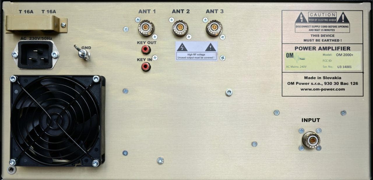
X8NX8NOM2000
Sep 08, 2014Amateur Radio Service Linear HF Amplifier
Equipment Class
AMP - Amplifier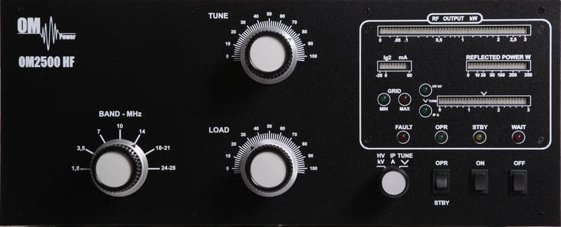
X8NX8NOM2500A
Dec 02, 2012Amateur Radio High Frequency Linear Amplifier
Equipment Class
AMP - Amplifier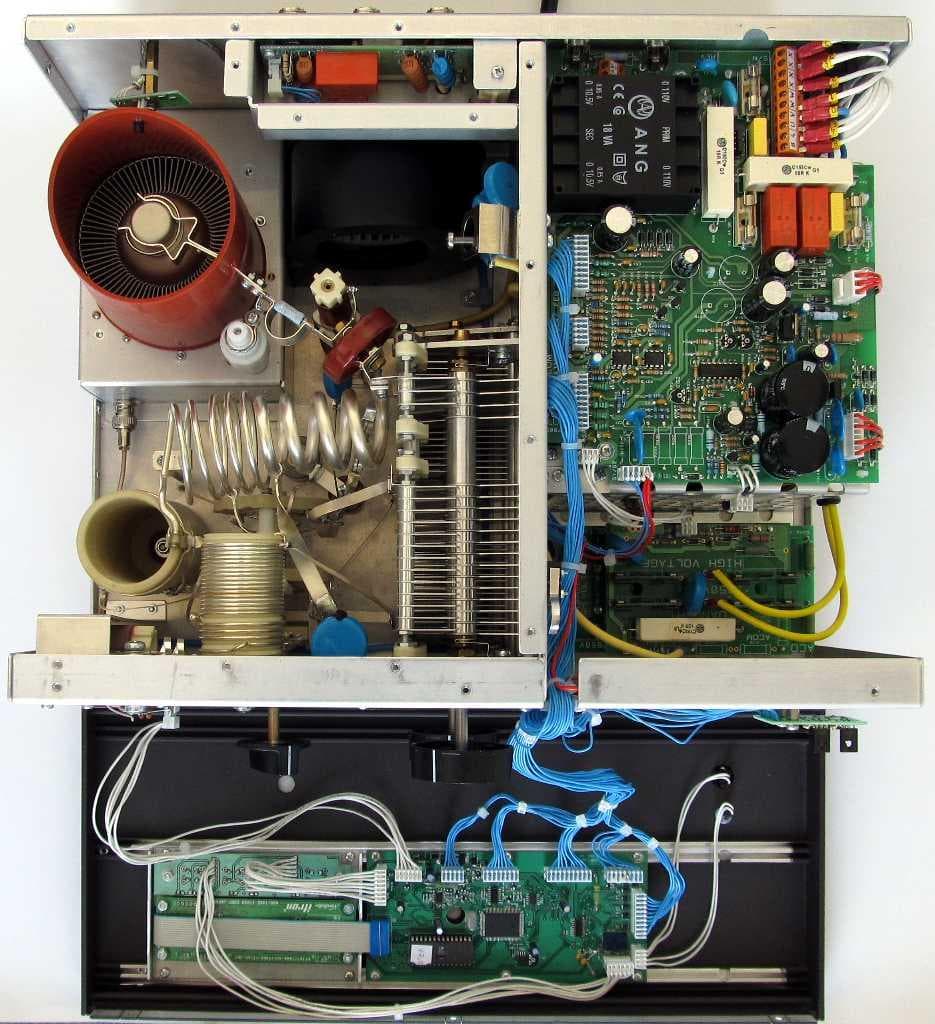
X8NX8NAA1500
Jun 06, 2012Amateur Radio Linear Amplifier
Equipment Class
AMP - Amplifier
X8NAA1011
May 02, 2010Amateur Radio RF Amplifier
Equipment Class
AMP - Amplifier