X8NX8NAA1500Amateur Radio Linear Amplifier
Array Solutions dba Array Solutions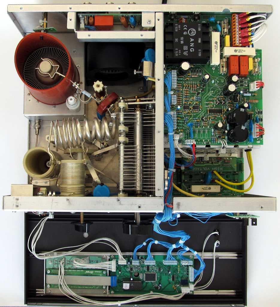
Click to zoom
Application Details
- Equipment Class
- AMP - Amplifier
- Date of Grant
- Jun 06, 2012
- Application Purpose
- Original Equipment
- Date of Application
- Apr 01, 2012
- Equipment Note
- Amateur Radio Linear Amplifier
- Frequency Range
- 1.80000000 - 54.00000000
- Country
- United States
Documents & Files
Document Text
Text extracted from the exhibit documents filed with the FCC. Open a document above to read the original.
Users Manual
1 Exhibit 6: User’s Manual External Radio Frequency Power Amplifier ACOM 1500 Model 1500 Array Solutions 2611 North Beltline Rd Suite 109 Sunnyvale, Texas 75182 USA Tel: 214 954 7140 fax: 214 954 7142 E-mail: [email protected] 2 Table of Contents 1. GENERAL INFORMATION .................................................................... ...3 1-1. Introduction and Description ................................................................ 3 1-2. Owner Assistance ................................................................................. 3 1-3. Equipment Supplied ............................................................................. 3 1-4. Features ............................................................................................... 3 1-5.Safety Considerations, Explicit Definitions ............................................. 4 2. INSTALLATION ...................................................................................... 6 2-1.Unpacking and Initial Inspection ............................................................ 6 2-2. Line Voltage Selection .......................................................................... 6 2-3. Amplifier Location Selection ................................................................. 6 2-4. Connections ......................................................................................... 7 2-5. Installation of External Fan ................................................................... 8 3. POWER ON, CONTROLS AND INDICATORS ......................................................... 9 4. OPERATION ......................................................................................... 11 4-1. Turning ON and OFF ........................................................................... 11 4-2. Changing Operate and Standby Modes ................................................ 11 4-3. Antenna charge .................................................................................. 12 4-4. Tuning ............................................................................................... 12 4-5. ON LINE Information Screens and Control Functions............................ 14 4-6. Auto-Protection System ...................................................................... 15 5. OFF LINE OPERATION ........................................................................... 16 5-1. Display brightness control ................................................................... 16 5-2. Auto-Operate enabling and disabling ................................................. 16 5-3. Antenna outputs assignment..........................................................................16 5-4. Reading Auto-protection Signatures ...........................................................16 3 6. MAINTENANCE .................................................................................................... 17 6-1. Cleaning..............................................................................................17 6-2. Fuses Replacement.................................................................................17 6-3. Tube Replacement..................................................................................17 6-4. The ACOM1500 Simplified Schematic Diagram................................................17 6-5. Troubleshooting.....................................................................................18 7. SPECIFICATIONS................................................................................20 7-1. Parameters............................................................................................20 7-2. Functions..............................................................................................20 7-3.Storage and Shipment................................................................................21 NOTE This unit has been set for 240VAC at the factory. Means is provided, however, to reconnect it for 200/240VAC, as well as for 100/120VAC, in 10-Volt steps. Please contact your dealer or look at the enclosed schematic diagram whenever a change is needed. 4 5 1. GENERAL INFORMATION 1-1. Introduction and Description This manual explains the installation, operation, and maintenance of the ACOM1500 HF+6 meters linear amplifier. The ACOM1500 is a complete and self-contained linear amplifier that covers all amateur bands from 1.8 through 54MHz and provides over 1500W PEP (1200W continuous carrier) output power with less than 85W exciter drive. Antenna VSWR up to 3:1 is acceptable at full power. Tuning is substantially simplified by a plate-load True Resistance Indicator (TRI) and by an automatically controlled input attenuator. Operating parameters are displayed by a multi-functional high brightness vacuum fluorescent display (VFD). Full break-in transmit/receive switching (QSK) is standard. 1-2. Owner Assistance If assistance is needed, you should contact your local dealer first. If you still have an issue you need to discuss with one of ACOM's specialists, the contact information is as follows: fax + 359 2 920 96 56, tel. + 359 2 920 96 55, e-mail [email protected] or by mail: bul. Nikola Mushanov Nr.151, 1330 Sofia, Bulgaria. 1-3. Equipment Supplied The ACOM1500 amplifier and this manual are shipped in a cardboard carton. 1-4. Features • Easy to operate. The TRI is a powerful tuning aid which, together with the automatically controlled input attenuator, helps the operator to quickly and precisely match antennas (5-10 seconds typically). The auto-operate function (when enabled) maintains the amplifier in OPERATE mode for you, thus saving manual operations and time. • No heavy outboard antenna tuners required for antenna VSWR up to 3:1 (and higher on some bands). Your amplifier will perform the functions of an antenna tuner, thus enabling you to change antennas faster and use them over a wider frequency range (saving tuning time). • An amplifier that is both user-friendly, and that…
Text truncated - open the document above for the full version.
Attestation Statements
Exhibit 9 page 1 of 3 Exhibit 9: Additional Information in Response to 47 CFR Ch.1 Sec. 2.1033 External Radio Frequency Power Amplifier ACOM 1500 Model 1500 Array Solutions 2611 North Beltline Rd Suite 109 Sunnyvale, Texas 75182 USA Tel: 214 954 7140 fax: 214 954 7142 E-mail: [email protected] Exhibit 9 page 2 of 3 Additional Information in Response to 47 CFR Ch.1 Sec. 2.1033 Section c.1. The "ACOM1500” HF linear amplifier will be assembled and production testing performed in the Republic of Bulgaria by the company “ACOM OOD”. ACOM OOD has been designed and manufactured external radio frequency power amplifiers for amateur use since 1990. The company has designed and manufactured the following types of amplifiers: - the "ETO 91B" HF Linear Amplifier accepted as FCC ID: DGVPA-91B which was marketed in the United States by Alpha/Power, Inc. of Colorado Springs, COLORADO continuously till 1999; - the "ACOM2000A” Automatic HF Linear Amplifier accepted as FCC ID: OITAA2000, which is in volume production and is being presently marketed in the United States by the Applicant; - the “ACOM1000” HF+6m Linear Amplifier accepted as FCC ID: OITAA1000, which is in volume production and is being presently marketed in the United States by the Applicant. - the “ACOM1010” HF Linear Amplifier accepted as FCC ID: SRRA1010, which is in volume production and is being presently marketed in the United States by the Applicant. - the “ACOM1011” HF Linear Amplifier accepted as FCC ID: X8NAA1011, which is in volume production and is being presently marketed in the United States by the Applicant. - ACOM, OOD is located at Bul.Nikola Musanov Nr.151, 1330 Sofia Bulgaria. The president and principal owner of ACOM, OOD is Mr. Vassil M. Vassilev. Applicant for certification, Array Solutions is a distributor of ACOM OOD products in North America. With respect to the subject, "ACOM1500” HF linear amplifier equipment, Applicant is responsible for all aspects of quality assurance, marketing and service in USA, as well as for the compliance with FCC rules. Array Solutions is located at 2611 North Beltline Rd, Suite 109, Sunnyvale, Texas 75182, USA. Applicant has conducted or observed all design proof testing and will re-test samples of production equipment on an ongoing basis to assure conformance to Applicant's quality standards, including all FCC regulatory requirements. Section c.2 This product designated "ACOM1500 HF linear amplifier”, hereafter "ACOM1500", is an external radio frequency power amplifier that covers all amateur bands from 1.8 through 54MHz and provides 1500W PEP output power with typically 85W-exciter drive, or 1200W continuous carrier. It is based on and is similar to our previous model ACOM1000 (FCC ID: OITAA1000) but uses more popular tube. The ACOM1500 will be marketed in the United States for use in the Amateur Radio Service. The FCC identifier for the ACOM1500 will be X8NAA1500 Section c.3 A copy of the Installation and Operating Instructions for the ACOM1500 is included as Exhibit 6. Section c.4 The equipment is suitable for all types of emission authorized for amateur HF use in 97.305 of FCC rules. Section c.5 The equipment is designed to meet all specifications and FCC performance standards on all amateur bands from 1.8 to 54MHz. When delivered to any buyer within FCC's jurisdiction, the equipment is not operable on frequencies between 26MHz and 28MHz according to FCC 97.317(b). Section c.6 The equipment can be operated at any power level up to 1500W PEP or 1200W continuous carrier. Lower power linear operation is possible by reducing RF excitation proportionately. An Exhibit 9 page 3 of 3 instantaneous peak-reading bargraph is provided for direct readout of output forward peak-power at any time. The numeric value of the output power can be read on the display too. Section c.7 The equipment is rated for maximum RF power output of 1500W PEP or 1200W continuous carrier Section c.8 Nominal voltages and currents at rated output (1200W) are: DC plate voltage: 2500V; DC plate current: 0.85A; DC screen voltage: 325V; DC screen current: 30mA;; DC grid bias: -60V (adjusted individually for 250mA idling plate current. Section c.9 Tune-up procedure is simplified by a plate-load True Resistance Indicator (TRI) which helps the operator to quickly and precisely match antennas and eliminates probability of inadvertent mistune. The antenna impedance matching capability is up to VSWR 3:1 or higher. The procedure description is included in Exhibit 11, as well as in the Operating Manual - Exhibit 6, Section 4-4. Section c.10 Several features of the ACOM1500 design are specifically intended to reduce spurious radiation to a minimum. In the input circuit, a non-inductive resistor load ensures that VSWR of 1.3:1 or less is presented to the exciter at the RF input terminal over the entire frequency range. The output circuit comprises a classic Pi-L network, which suppresses the harmonic emissions. Results of our ACOM1500 performance tests are included in Exhibit 5. RF performance and spurious emissions are generally the same as that of "ETO91B", “ACOM2000A”, “ACOM1000”, “ACOM1010” and “ACOM1011”. Section c.11 A photograph showing the design of the FCC identification label for the ACOM1500 is included as Exhibit 1. Section c.12 Photographs showing the construction and layout of the ACOM1500 are included as Exhibits 2 and 7. Section c.13 Not applicable to external RF power amplifies. Section c.14 Not applicable, as provided in Section c.15. Section c.15 Measurement data indicating compliance with requirements of Part 97.307 and Part 97.317 is included as Exhibits 5 and 10. Section c.16 Not applicable to external RF power amplifiers. Section c.17 Not applicable to external RF power amplifiers. The subject equipment application is not part of a composite system.
Block Diagram
Exhibit 3 page 1 of 2 Exhibit 3: Block Diagram External Radio Frequency Power Amplifier ACOM 1500 Model 1500 Array Solutions 2611 North Beltline Rd Suite 109 Sunnyvale, Texas 75182 USA Tel: 214 954 7140 fax: 214 954 7142 E-mail: [email protected] Exhibit 3 page 2 of 2 Block Diagram
ID Label/Location Info
Exhibit 1 page 1 of 3 Exhibit 1: ID Label Location Info External Radio Frequency Power Amplifier ACOM 1500 Model 1500 Array Solutions 2611 North Beltline Rd Suite 109 Sunnyvale, Texas 75182 USA Tel: 214 954 7140 fax: 214 954 7142 E-mail: [email protected] Exhibit 1 page 2 of 3 FCC ID and Label Location Information In compliance with FCC Regulation 47 CFR Ch. 1 part 2.925, the ACOM 1500, External Radio Frequency Power Amplifier, Model 1500 bears a label located on the rear plate of the equipment which displays the following FCC Identifier: Part (a) 1. The term FCC ID followed by the three digit Grantee Code and the six digit Equipment Product Code. 2. Not applicable. 3. Not applicable. Part (b) Not applicable Part (c) Reserved Part (d) 1. The ACOM 1500 label is indelibly printed on the rear panel of the equipment. This label will last the lifetime of the equipment in the environment in which the equipment will be operated and is not readily detachable. 2. The ACOM 1500 label is readily visible on the outside of the equipment enclosure. Part (e) Not applicable. Part (f) 1. The size of the label is 3.5 by 1.2 inches. The label and its location on the equipment are shown in the following pictures. Fig.1 Label location Exhibit 1 page 3 of 3 Fig.2 The label The Serial Number consists of 6 digit, where the first two digits represent the year of manufacture. In the FCC ID # Grantee code is: XN8 and the AA1500 portion is the equipment product code.
Internal Photos
Exhibit 7 page 1 of 3 Exhibit 7: Internal Photos External Radio Frequency Power Amplifier ACOM 1500 Model 1500 Array Solutions 2611 North Beltline Rd Suite 109 Sunnyvale, Texas 75182 USA Tel: 214 954 7140 fax: 214 954 7142 E-mail: [email protected] Exhibit 7 page 2 of 3 Fig.1 Right side View Fig.2 Left side View Exhibit 7 page 3 of 3 Fig.3 Top View Front Panel Down Fig.5 Bottom View – Tube Deck (screen cover removed)
Operational Description
Exhibit 8 page 1 of 3 Exhibit 8: Operational Description External Radio Frequency Power Amplifier ACOM 1500 Model 1500 Array Solutions 2611 North Beltline Rd Suite 109 Sunnyvale, Texas 75182 USA Tel: 214 954 7140 fax: 214 954 7142 E-mail: [email protected] Exhibit 8 page 2 of 3 Operational Description The ACOM1500 is a complete and self-contained linear amplifier that covers the amateur band 1.8-54MHz and provides 1500W PEP or 1200W CW output power with typically 85W- exciter drive. It is based on and is very similar to our previous model ACOM1000 (FCC ID: OITAA1000) but the final tube has been replaced by a more popular one. Amplifier’s tuning is simplified by a plate-load True Resistance Indicator (TRI) which helps the operator to quickly and precisely match antennas and eliminates probability of inadvertent mistune. The antenna impedance matching capability is up to VSWR 3:1 or higher. A fixed matching circuit to the tubes input is employed which results in a very good load to the exciter over the entire frequency band from 1.8 to 54MHz, yielding a good linearity. Look at the schematic diagram (Exhibit 3). The high-performance ceramic-metal radial beam tetrode V1, type 4CX1000A, with a plate dissipation of 1000W, is grid-driven. It can dissipate up to 1000W when forced air cooled and is specifically designed for class AB1 RF linear amplifiers. The input signal from the RF INPUT jack is passed through a broadband input matching circuit, which comprises some components in the INPUT PCB and a 50 Ohm/100W RF swamping resistor (Rsw). This circuit tunes out the tube input capacitance. The swamping resistor Rsw is not an attenuator but it is a termination load for this circuit. It could not be eliminated since a severe impedance mismatch to the driver would prevent using the amplifier at all. Cathode resistors Rc create DC and RF negative feedback, thus stabilizing the gain and equalizing the frequency response. The varistor VSsg in the screen grid circuit protects the tube and the screen grid voltage regulator in the events of an internal tube flashover. The nominal voltages and currents of the tubes at rated output power are as follows: DC plate voltage: 2250V for SSB and 2000V for RTTY; DC plate current: 0.5A for SSB and 0.45A for RTTY (bot tubes totally); DC screen voltage: 290V; DC screen current: 30mA (bot tubes totally); DC grid bias: -45...-50V (adjusted individually for 195mA idling plate current (both tubes totally). The combination LpI-RpI in the plate circuit is a VHF/UHF parasitic suppressor. DC plate voltage is fed through chokes RFCI-RFC2 and the capacitor Cb3 blocks it from the output. The output circuit comprises LPI, LP2, LL, CPI-CP3, and CLI-CL3 which form a classic Pi-L network and suppress the harmonic frequency emissions. This tank is switched and tuned over the bands by SIA-SIC and the air variable capacitors CPI, 2 and CLI, 2. The output signal is fed through an additional VHF low-pass filter for frequencies above 55MHz (LfI, Lf2 and Cf). Then it is passed through the vacuum antenna relay KI, wattmeter current transformer TAI, and a high-pass filter RFCasw-Casw for frequencies below I00kHz, to the antenna switch and the three outputs. The chokes RFC3 and RFCasw keep track of the antenna relay contact conditions and together with Casw prevent the plate supply from reaching the antenna. RFCasw shunts the high voltage to ground should the DC blocking capacitor Cb3 fail. The resistor Rasw protects the amplifier from charging Electro-static energy fed by the antenna. The PLATE CAPACITIVE DIVIDER and RF WATTMETER are the main sources of information for the control circuit of the amplifier during the antenna impedance matching process. The control circuit is based on the 80C552 micro-controller from Philips. Exhibit 8 page 3 of 3 All suupply voltages are delivered from the MAINS&LOW VOLTAGE and HIGH VOLTAGE SUPPLY PCBs. The control grid, screen grid, and plate currents, plate cooling airflow temperature, reflected power etc. are permanently monitored. Many software-derived protections are based on this information.
Operational Description
Exhibit 11 Page 1 of 16 Exhibit 11: Tuning Procedure and Parts List External Radio Frequency Power Amplifier ACOM 1500 Model 1500 Exhibit 11 Page 2 of 16 Array Solutions 2611 North Beltline Rd Suite 109 Sunnyvale, Texas 75182 USA Tel: 214 954 7140 fax: 214 954 7142 E-mail: [email protected] 4-4. Tuning Tuning is possible only in operate mode, so you may need to press the OPER button in order to illuminate the LED above it (unless Auto-Operate is active). a) Preliminary information. Tuning the amplifier is a procedure of matching the impedance of the currently used antenna to the optimum tube load resistance. This will ensure maximum plate efficiency and RF gain at nominal output power, with minimum IMD at that. Please note, that the REFLECTED POWER readings and the measured VSWR depend on the antenna impedance only, and not on the amplifier tuning. If the antenna impedance is different from 50-Ohm pure resistive (nominal), the REFLECTED POWER reading will always indicate reflected power presence (even at a perfect tuning). Proper tuning will allow operation at greater power without distortion or danger to the amplifier. Note also that the real OUTPUT POWER in the load is equal to the difference between the FORWARD- and REFLECTED- readings. For instance, at a reading of FORWARD I500W and REFLECTED 250W, the real OUTPUT POWER will be equal to their difference - I250W (into a 2.4:1 VSWR load). At very high VSWR (no antenna or badly mismatched antenna), the FORWARD and REFLECTED readings will be almost equal, while the real OUTPUT POWER (the difference between them) will be practically zero. Exhibit 11 Page 3 of 16 The amplifier can operate safely if the following rule is obeyed: "REFLECTED POWER < 300W". Matching is assured for loads with VSWR up to 3:1. Nevertheless, for some loads and bands matching is possible at even higher VSWR. The maximum usable forward power at VSWR 3:1 is 1200W with 300W reflected. For higher than 300W reflected power you'll get the ** REFLECTED POWER ** soft-fault protection trip. For instance, this can happen at full-scale I500W forward and 375W reflected power, into an antenna having a VSWR of 3:1 or worse. C A U T I O N Using a feeder of coaxial cable at VSWR > 3:1 on HF, and particularly on the and 6 meters bands, is not recommended. At such high values of VSWR, the high voltages, high currents, and heat associated with line losses, risk to permanently damage your coaxial cable or antenna switch. Update amplifier tuning when you change the band or between CW and SSB segments within the same band. Update it each time when you change the antenna, even in the same band, as well as periodically, even though you may have not changed band or antenna. Be on the alert in particular when a significant change in the environment occurs (snow, ice, newly appeared or removed massive objects, alien wires nearby etc.) that would cause significant changes in the antenna impedance and eventually an increased VSWR. N O T E If you use more than one antenna per band, it is necessary that you select the proper antenna BEFORE the next step. Retune after selecting a different antenna for the same band, since the impedances may differ substantially (unless their VSWR is excellent, i.e. below I.2:I for both). C A U T I O N Do not switch the BAND switch knob while transmitting with the amplifier! Hot switching (while transmitting) will eventually destroy the band switch, not covered by the warranty! C A U T I O N When tuning, do not apply continuous drive longer than 3 minutes and after that pause I-2 minutes for tube cooling. We recommend that you tune-up at the center frequencies of the preferred frequency band. First select the band switch and the correct antenna number (never with RF applied!). Then use table 4-I in order to achieve an approximate preset for both TUNE capacitor and LOAD capacitor knobs: Band, MH zTune Knob DialLoad Knob Dial 1.8 - 262 - 3065 - 38 3.5 - 459 - 4072 - 53 7 - 7.357 - 5565 - 60 10.1 - 10.215 - 1427 - 26 14 - 14.3560 - 5032 - 30 18 - 18.270 - 6867 - 65 21 - 21.4519 - 1547 - 44 24.9 - 2567 - 6660 - 59 28 - 29.726 - 1246 - 39 50 - 5432 - 1324 - 20 Exhibit 11 Page 4 of 16 Table 4-I. Approximate tuning presets b) Selecting the plate-load True Resistance Indicator (TRI) tuning aid. You may select TRI scale in three different ways: - By pressing simultaneously the PREV+NEXT buttons shortly. This will insert a 6dB attenuator between the driver and the amplifier's input (the ATT LED will light), so you'll not need to reduce the drive power during tuning. Press PREV+NEXT buttons momentarily again to switch the attenuator off the input and to return to the old screen. If you use any of PREV or NEXT buttons only, the attenuator would be switched off too, but the information screen would change to respectively previous or next. - By pressing repeatedly either PREV or NEXT button (whichever is nearest), until you reach the TRI scale. This will not insert the attenuator, so you'll have to use less than 20W drive (unless the amplifier is near correct tuning), otherwise the next step would be executed automatically: - By simply applying a normal working (60-85W) drive power, while the amplifier is not yet tuned. This will automatically invoke the TRI tuning aid and will insert the input attenuator (the ATT LED will light) after one second. The attenuator will be switched off, and the old screen will be returned automatically, after you release the PTT shortly. If you have achieved meanwhile a nearly good tuning, the attenuator would not be inserted again. If the old screen was the same (TRI, selected manually earlier), you'll then be able to precisely tune the amplifier also at nominal power, without changing drive at all. Use this hint to shorten the tuning process duration. c) Tuning Procedure. While a continuous (CW) signal at the desired frequency is still applied: - Look at the upper scale (forward power); obtain maximum power using the upper (TUNE) knob; - L…
Text truncated - open the document above for the full version.
Parts List/Tune Up Info
Exhibit 11 Page 1 of 16 Exhibit 11: Tuning Procedure and Parts List External Radio Frequency Power Amplifier ACOM 1500 Model 1500 Exhibit 11 Page 2 of 16 Array Solutions 2611 North Beltline Rd Suite 109 Sunnyvale, Texas 75182 USA Tel: 214 954 7140 fax: 214 954 7142 E-mail: [email protected] 4-4. Tuning Tuning is possible only in operate mode, so you may need to press the OPER button in order to illuminate the LED above it (unless Auto-Operate is active). a) Preliminary information. Tuning the amplifier is a procedure of matching the impedance of the currently used antenna to the optimum tube load resistance. This will ensure maximum plate efficiency and RF gain at nominal output power, with minimum IMD at that. Please note, that the REFLECTED POWER readings and the measured VSWR depend on the antenna impedance only, and not on the amplifier tuning. If the antenna impedance is different from 50-Ohm pure resistive (nominal), the REFLECTED POWER reading will always indicate reflected power presence (even at a perfect tuning). Proper tuning will allow operation at greater power without distortion or danger to the amplifier. Note also that the real OUTPUT POWER in the load is equal to the difference between the FORWARD- and REFLECTED- readings. For instance, at a reading of FORWARD I500W and REFLECTED 250W, the real OUTPUT POWER will be equal to their difference - I250W (into a 2.4:1 VSWR load). At very high VSWR (no antenna or badly mismatched antenna), the FORWARD and REFLECTED readings will be almost equal, while the real OUTPUT POWER (the difference between them) will be practically zero. Exhibit 11 Page 3 of 16 The amplifier can operate safely if the following rule is obeyed: "REFLECTED POWER < 300W". Matching is assured for loads with VSWR up to 3:1. Nevertheless, for some loads and bands matching is possible at even higher VSWR. The maximum usable forward power at VSWR 3:1 is 1200W with 300W reflected. For higher than 300W reflected power you'll get the ** REFLECTED POWER ** soft-fault protection trip. For instance, this can happen at full-scale I500W forward and 375W reflected power, into an antenna having a VSWR of 3:1 or worse. C A U T I O N Using a feeder of coaxial cable at VSWR > 3:1 on HF, and particularly on the and 6 meters bands, is not recommended. At such high values of VSWR, the high voltages, high currents, and heat associated with line losses, risk to permanently damage your coaxial cable or antenna switch. Update amplifier tuning when you change the band or between CW and SSB segments within the same band. Update it each time when you change the antenna, even in the same band, as well as periodically, even though you may have not changed band or antenna. Be on the alert in particular when a significant change in the environment occurs (snow, ice, newly appeared or removed massive objects, alien wires nearby etc.) that would cause significant changes in the antenna impedance and eventually an increased VSWR. N O T E If you use more than one antenna per band, it is necessary that you select the proper antenna BEFORE the next step. Retune after selecting a different antenna for the same band, since the impedances may differ substantially (unless their VSWR is excellent, i.e. below I.2:I for both). C A U T I O N Do not switch the BAND switch knob while transmitting with the amplifier! Hot switching (while transmitting) will eventually destroy the band switch, not covered by the warranty! C A U T I O N When tuning, do not apply continuous drive longer than 3 minutes and after that pause I-2 minutes for tube cooling. We recommend that you tune-up at the center frequencies of the preferred frequency band. First select the band switch and the correct antenna number (never with RF applied!). Then use table 4-I in order to achieve an approximate preset for both TUNE capacitor and LOAD capacitor knobs: Band, MH zTune Knob DialLoad Knob Dial 1.8 - 262 - 3065 - 38 3.5 - 459 - 4072 - 53 7 - 7.357 - 5565 - 60 10.1 - 10.215 - 1427 - 26 14 - 14.3560 - 5032 - 30 18 - 18.270 - 6867 - 65 21 - 21.4519 - 1547 - 44 24.9 - 2567 - 6660 - 59 28 - 29.726 - 1246 - 39 50 - 5432 - 1324 - 20 Exhibit 11 Page 4 of 16 Table 4-I. Approximate tuning presets b) Selecting the plate-load True Resistance Indicator (TRI) tuning aid. You may select TRI scale in three different ways: - By pressing simultaneously the PREV+NEXT buttons shortly. This will insert a 6dB attenuator between the driver and the amplifier's input (the ATT LED will light), so you'll not need to reduce the drive power during tuning. Press PREV+NEXT buttons momentarily again to switch the attenuator off the input and to return to the old screen. If you use any of PREV or NEXT buttons only, the attenuator would be switched off too, but the information screen would change to respectively previous or next. - By pressing repeatedly either PREV or NEXT button (whichever is nearest), until you reach the TRI scale. This will not insert the attenuator, so you'll have to use less than 20W drive (unless the amplifier is near correct tuning), otherwise the next step would be executed automatically: - By simply applying a normal working (60-85W) drive power, while the amplifier is not yet tuned. This will automatically invoke the TRI tuning aid and will insert the input attenuator (the ATT LED will light) after one second. The attenuator will be switched off, and the old screen will be returned automatically, after you release the PTT shortly. If you have achieved meanwhile a nearly good tuning, the attenuator would not be inserted again. If the old screen was the same (TRI, selected manually earlier), you'll then be able to precisely tune the amplifier also at nominal power, without changing drive at all. Use this hint to shorten the tuning process duration. c) Tuning Procedure. While a continuous (CW) signal at the …
Text truncated - open the document above for the full version.
Contact Information
Applicant
John Terleski(President)
Technical Contact
Array SolutionsJohn David Terleski
[email protected]214 954 7140
2611 N. Belt Line Rd · Sunnyvale, Texas · United States
Technical Specifications
| # | Rule Parts | Frequency Range | Power Output | Emission | Tolerance |
|---|---|---|---|---|---|
| 1 | 97 | 1.8 MHz - 54 MHz | 1200 W | XXX | Amp |
Other Applications from Array Solutions dba Array Solutions
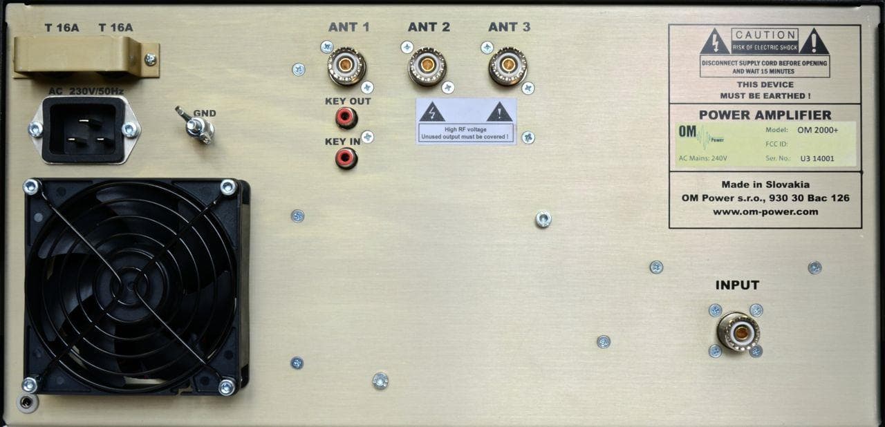
X8NX8NOM2000
Sep 08, 2014Amateur Radio Service Linear HF Amplifier
Equipment Class
AMP - Amplifier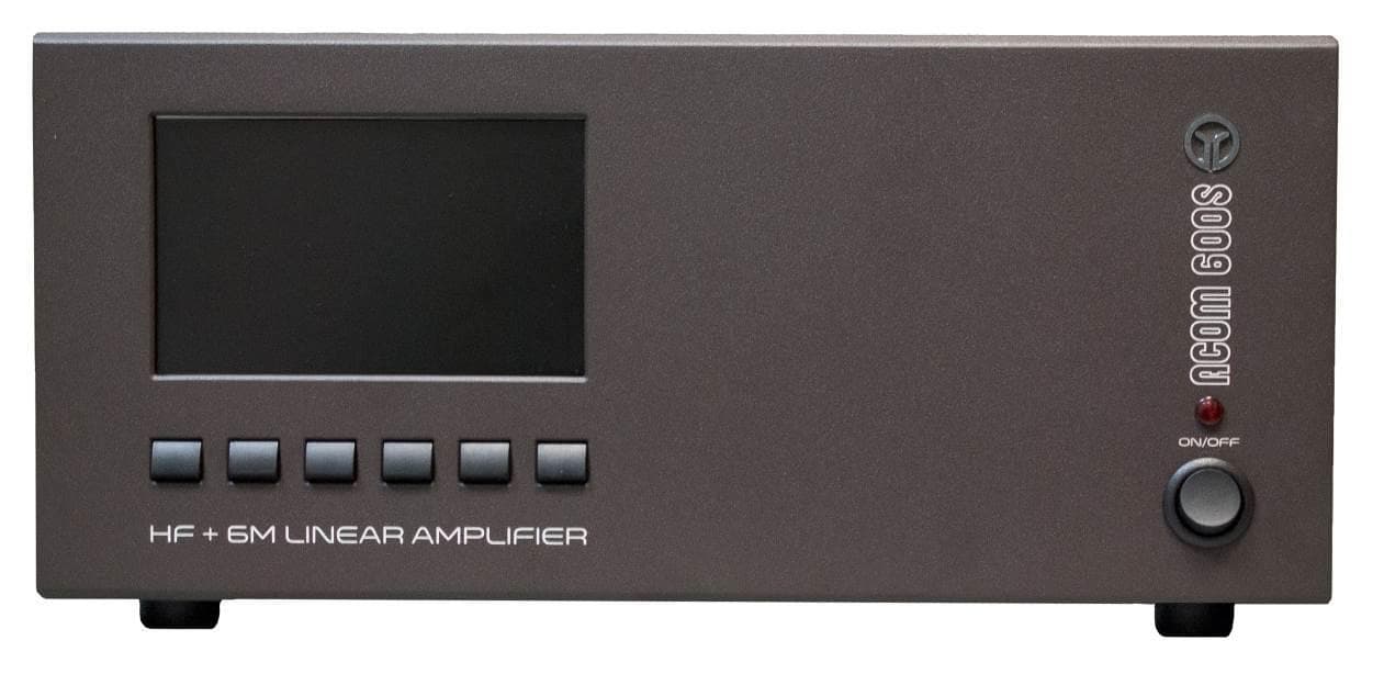
X8NA600S
Apr 29, 2014Amateur Radio Linear Amplifier
Equipment Class
AMP - Amplifier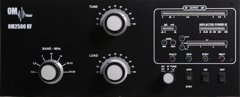
X8NX8NOM2500A
Dec 02, 2012Amateur Radio High Frequency Linear Amplifier
Equipment Class
AMP - Amplifier
X8NAA1011
May 02, 2010Amateur Radio RF Amplifier
Equipment Class
AMP - Amplifier