X8NX8NOM2500AAmateur Radio High Frequency Linear Amplifier
Array Solutions dba Array Solutions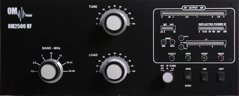
Click to zoom
Application Details
- Equipment Class
- AMP - Amplifier
- Date of Grant
- Dec 02, 2012
- Application Purpose
- Original Equipment
- Date of Application
- Sep 13, 2012
- Equipment Note
- Amateur Radio High Frequency Linear Amplifier
- Frequency Range
- 1.80000000 - 29.70000000
- Country
- United States
Documents & Files
Document Text
Text extracted from the exhibit documents filed with the FCC. Open a document above to read the original.
Users Manual
Exhibit 6 page 1 of 33 OM Power Exhibit 6: User’s Manual External Radio Frequency Power Amplifier OM2500A Model OM2500A Array Solutions 2611 North Beltline Rd Suite 109 Sunnyvale, Texas 75182 USA Tel: 214 954 7140 fax: 214 954 7142 E-mail: [email protected] Exhibit 6 page 2 of 33 TABLE OF CONTENTS 1. GENERAL INFORMATION 1.1. Introduction .......................................................................... 4 1.2. Specification ......................................................................... 4 1.2.1. Parameters ............................................................................ 4 1.2.2. Protection Circuits .................................................................. 4 1.2.3. Indicators ............................................................................. 5 2. SAFETY INSTRUCTIONS ...................................................... 6 3. GENERAL DESCRIPTION ....................................................... 7 3.1. HF part ............................................................................... 7 3.2. Power Supply ....................................................................... 8 3.3. Safety Devices ...................................................................... 8 4. INSTALLATION .................................................................. 8 4.1. Grounding ........................................................................... 8 4.2. Coaxial Cable ......................................................................... 9 4.3. I/O Box and Interface ............................................................... 9 4.4. Main Supply ......................................................................... 11 4.5. Cooling ............................................................................... 12 4.6. Remote Control ..................................................................... 12 5. OPERATION ........................................................................ 12 5.1. Operation Elements ................................................................. 13 5.2. Configuration of Power Amplifier ................................................ 14 5.2.1. TCVR Support Settings ............................................................. 15 5.2.2. Connection with no supported TCVRs ............................................ 16 5.2.3. Communication Loss ................................................................ 16 5.2.4. Antenna Switching Menu ........................................................... 17 5.2.5. Bandpass Filter Settings ............................................................ 17 5.2.6. Loading Factory Default Settings ................................................. 18 Exhibit 6 page 3 of 33 5.2.7. MUTE Option ....................................................................... 18 5.2.8. LCD Settings Menu ................................................................ 19 5.2.9. Operation in MANUAL Mode ................................................... 19 5.3. Tuning of Power Amplifier ..................................................... 20 5.3.1. Manual Tuning ..................................................................... 20 5.3.2. Tuning Adjustment ............................................................... 22 6. MAINTENANCE ................................................................ 23 6.1. Indication of Fault Conditions ................................................. 23 6.2. Fuse Replacement ................................................................ 24 6.3. Tube Replacement ................................................................ 24 6.4. Cleaning ........................................................................... 24 7. APPENDIX ....................................................................... 25 7.1. Example of connection for ICOM ............................................. 25 7.2. Example of connection for ELECRAFT ....................................... 26 7.3. Example of connection with YAESU .......................................... 27 7.4. Example of connection with Antenna switch and BPF ...................... 28 7.5. Example of connection USB micro KEYER II with IC7800 or IC7700 .......................................................... 29 7.6. Example of connection USB micro KEYER II with another Icom ................................................................. 30 7.7. Example for connection USB micro KEYER II with Yeasu or ELECRAFT .................................................... 31 7.8. Example of connection PA with MicroHAM MKII, (MK2R+ etc ) with CI-V output ....................................................................................... 32 7.9. Block Diagram of OM2500A Power Amplifier (USA version)................. 33 Exhibit 6 page 4 of 33 1. GENERAL INFORMATION 1.1. Introduction The OM Power model OM2500A is a fully automatic, full legal limit amplifier, designed for heavy duty use on all short wave amateur bands from 1.8 to 29.7 MHz (including WARC bands) and all modes with no time limit. It is equipped with one GU84b ceramic tetrode. THE ADVANTAGES OF OM2500 A Full compatibility with: ICOM, ELECRAFT ,KENWOOD, TEN-TEC ORION , Yaesu and CI-V data. Automatic switching between bands Automatic tuning with the band according to segments Automatic switching of band pass filter Automatic switching of antenna switches The possibility to use 2 different antennas within one band or segment 1.2. Specification 1.2.1. Parameters Frequency Coverage Amateur Bands 1.8 – 29.7 MHz including WARC Power Output 1500w PEP continuous output all modes - *no time limit* Input Power 60 – 80W for full output power Input Impedance 50 Ohm, VSWR < 1.2 : 1 Power Gain 15 dB Output impedance 50 Ohm unbalanced Maximum output SWR 2:1 SWR protection: automatic switching to STBY , when reflected power is 350Wor higher Intermodulation distortion 36 dB below nominal output Suppression of harmonics < -52 dBc second, < -65 dB…
Text truncated - open the document above for the full version.
Users Manual
Instruction Manual OM2500 HF SHORTWAVE POWER AMPLIFIER OM POWER, s. r. o. 930 30 Báč 126 SLOVAKIA E-mail: [email protected] 2 TABLE OF CONTENTS 1. GENERAL INFORMATION 1.1. Introduction .......................................................................... 4 1.2. Specification ......................................................................... 4 1.2.1. Parameters ............................................................................ 4 1.2.2. Protection Circuits .................................................................. 4 1.2.3. Indicators ............................................................................. 5 2. SAFETY INSTRUCTIONS ...................................................... 5 3. GENERAL DESCRIPTION ....................................................... 6 3.1. HF part ............................................................................... 6 3.2. Power Supply ....................................................................... 7 3.3. Safety Devices ...................................................................... 8 4. INSTALLATION .................................................................. 8 4.1. Grounding ........................................................................... 8 4.2. Coaxial Cable ......................................................................... 8 4.3. Control Cable ......................................................................... 9 4.4. Main Supply ......................................................................... 10 4.5. Cooling ............................................................................... 10 5. OPERATION ........................................................................ 10 5.1. Operation Elements ................................................................. 11 5.2. Tuning of Power Amplifier ..................................................... 12 6. MAINTENANCE ................................................................ 14 6.1. Indication of Fault Conditions ................................................. 14 6.2. Fuse Replacement . .............................................................. 15 6.3. Tube Replacement ................................................................ 16 6.4. Cleaning ........................................................................... 16 3 7. APPENDIX ........................................................................ 16 7.1. Band Blocking ..................................................................... 16 7.2. Block Diagram of OM2500 HF Power Amplifier (USA version) ............ 17 4 1. GENERAL INFORMATION 1.1. Introduction The OM Power model OM2500HF is a manual tuning, full legal limit amplifier, designed for heavy duty use on all short wave amateur bands from 1.8 to 29.7 MHz (including WARC bands) and all modes with no time limit. It is equipped with one GU84b ceramic tetrode. 1.2. Specification 1.2.1. Parameters Frequency Coverage Amateur Bands 1.8 – 29.7 MHz including WARC Power Output 1500w PEP continuous output all modes - *no time limit* Input Power 40 to 60W for full output power Input Impedance 50 Ohm, VSWR < 1.5 : 1 Power Gain typically 15 dB Output impedance 50 Ohm unbalanced Maximum output SWR 2:1 SWR protection: automatic switching to STBY , when reflected power is 350W or higher Intermodulation distortion 36 dB below nominal output Suppression of harmonics < -52 dBc second, < -65 dBc third Tube GU84b Ceramic tetrode Cooler Centrifugal blower + axial blower Power supply 240 V - 60 Hz Transformers 2 pcs of toroidal transformer 2,0 kVA Parameters 485 mm x 200 mm x 455 mm [19.1” x 7.9” x 17.9”] (width x height x depth) Weight 38 kg ( 84 lb ) 1.2.2. Protection Circuits There are 8 special protection circuits used in the amplifier. They are activated when one or more of next parameters exceed defined values or some unwanted occasion occurs. VSWR too high Anode current too high Screen current too high Grid current too high Mistuning of PA Hot switching protection Soft start for protecting your fuses “switch-on blocking “ at opened amplifier 5 1.2.3. Indicators There are couples of LED and bar graph indicators visible on the front panel to inform you about value of some parameters or operation status: Bar graph indicators Power output - 50 LED Reflected power – 20 LED Current at screen Ig2 – 10 LED Anode voltage, anode current, tuning – 30 LED LED Indicators Current at control grid (Ig1 – 2 LED) WAIT – preheating of tube (180 sec) STBY – standby OPR – operation condition FAULT – failure, switching off for abt. 4 sec 2. SAFETY INSTRUCTIONS WARNING! DANGEROUS HIGH VOLTAGE! The power amplifier is using high voltage up to close 3000V DC, which is very dangerous for human life! Read next safety instructions carefully first, before you will start to install and operate power amplifier! NEVER VIOLATE NEXT RULES! WARNING! NEVER ALLOW CHILDREN to play around PA or to touch power amplifier or connected cables in working condition, or to push anything into the case holes! WARNING! The amplifier contains high voltage circuits. Never turn the amplifier on without the upper lid in place. DO NOT ATTEMPT TO SHORT OR BYPASS safety switch under upper lid! WARNING! The OM2500 HF amplifier is neither to be used in a WET or HUMID environment nor to be exposed to RAINFALL! WARNING! Do not turn the amplifier on without having connected the ANTENNA or properly rated DUMMY LOAD! A hazardous HF voltage may build up on the antenna connector after turning the amplifier on with no antenna or dummy load connected! 6 WARNING! Before opening the upper lid of the amplifier make sure that power supply has been disconnected AT LEAST 10 minutes allowing the electrolytic capacitors to discharge fully. Disconnect power cord from the outlet! CAUTION! The amplifier must be installed in such a way that free flow of hot air from the tube is allowed. The amplifier must not be installed in a constrained surroun…
Text truncated - open the document above for the full version.
Attestation Statements
Fig. 1 Setup Block Diagram for OM2500A EUT RF Out RF in Ant Power amplifier HP437B Power meter HP8591E Spectrum analyzer ATT 20dB 30 dB 50 Ohm / 2 kWAttenuator Bird OM2500A meter LP100A Input Power K3 Transceiver
Attestation Statements
Exhibit 9 page 1 of 4 OM Power Exhibit 9:Additional Information in Response to 47 CFR Ch.1 Sec.2.1033 External Radio Frequency Power Amplifier OM2500A Model OM2500A Array Solutions 2611 North Beltline Rd Suite 109 Sunnyvale, Texas 75182 USA Tel: 214 954 7140 fax: 214 954 7142 E-mail: [email protected] Exhibit 9 page 2 of 4 Additional Information in Response to 47 CFR Ch.1 Sec. 2.1033 Section c.1 The OM2500A HF linear amplifier will be assembled and product testing will be performed in the Slovak Republic by the private company OM POWER LTD. OM POWER has been designing and manufacturing external radio frequency power amplifiers for amateur use since 2004. The company has designed and manufactured the following types of amplifiers: OM2500HF OM2500A OM3500HF OM3500A OM2000 OM POWER LTD has its seat at Bac 126, 93030 Rohovce, Slovak Republic. The owners and executives of the company are Tibor Ferenec and Jozef Lang. Applicant for certification, Array Solutions is a distributor of OM POWER LTD products in North America. With regard to the subject, “OM2500A” HF linear amplifier equipment, Applicant is responsible for all aspects of quality assurance, marketing and service in the USA, as well as for the compliance FCC rules. Array Solution is located at 2611 North Beltline Rd, Suite 109, Sunnyvale, Texas 75182, USA. Applicant has conducted or observed all design-proof testing and will re-test samples of production equipment on an ongoing basis to assure conformity to Applicant’s quality standards, including all FCC regulatory requirements. Section c.2 This product designated “OM2500A HF linear amplifier”, hereinafter “OM2500A”, is an external radio frequency power amplifier that cover all amateur band from 1.8 through 29.7 MHz and provides 1500 W PEP output power with typically 60W exciter drive, or 500W output continuous carrier. The OM2500A will be marketed in the United States for use in the Amateur Radio Service. The FCC identifier for the OM2500A will be.............. Section c.3 A copy of the Installation and Operating Instructions for the OM2500A is included in Exhibit 6. Section c.4 The equipment is suitable for all types of emissions authorized for amateur HF use in 97.305 of FCC rules. Section c.5 Exhibit 9 page 3 of 4 The equipment is designed to meet all specifications and FCC performance standards on all amateur bands from 1.8 to 29.7 MHz. When delivered to any buyer within FCC’s jurisdiction, the equipment is not operable on frequencies between 24MHz and 35MHz according to FCC 97.317(b). Section c.6 The equipment can be operated at any power level up to 1500W PEP. Lower power linear operation (up to 500W continuous carrier) is possible in “RTTY” mode and by reducing RF excitation proportionately. Section c.7 The equipment is rated for maximum RF power output of 1500W PEP or 500W output continuous carrier, 50% duty cycle. It is limited to 800W maximum (including reflected power). Section c.8 Nominal voltages and currents at rated output 1500W are: DC plate voltage: 2800V for SSB and 2800V for RTTY; DC plate current: 1,0A for SSB and 1,0A for RTTY; DC screen voltage: 360V DC screen current: 20mA DC grid bias: -60-70V (adjusted individually for 400mA idling plate current Section c.9 Tune-up procedure is simplified by a TUNE Indicator which helps the operator to quickly and precisely match antennas and eliminates probability of inadvertent mistune. The antenna impedance matching capability is up to VSWR 3:1 or higher. The procedure description is included in Exhibit 11, as well as in the Operating Manual – Exhibit 6, Section 4-5. Section c.10 Several features of the OM2500A design are specifically intended to reduce spurious radiation to minimum. In the input circuit, a non-inductive resistor load ensures that VSWR of 1.3:1 or less is presented to the exciter at the RF input terminal over the entire frequency range. The output circuit comprises a classic Pi-L network, which suppresses the harmonic emissions. Results of our OM2500A performance tests are included in Exhibit 5. Section c.11 A photograph showing the design of the FCC identification label for OM2500A is included in Exhibit 1. Section c.12 Exhibit 9 page 4 of 4 Photographs showing the construction and layout of OM2500A are included as Exhibits 2 and7. Section c.13 Not applicable to external RF power amplifiers. Section c.14 Not applicable, as provided in Section c.15. Section c.15 Measurement data indicating compliance with requirements of Part 97.307 and Part 97.317 is included as Exhibits 5 and 10. Section c.16 Not applicable to external RF power amplifiers. Section c.17 Not applicable to external RF power amplifiers. The subject equipment application is not part of a composite system. Photo – FCC label design OM2500 A XXXX XXXX
Block Diagram
OM 2500HF Block diagram T25AT25A
External Photos
Exhibit 2 page 1 of 2 OM Power Exhibit 2: External Photos External Radio Frequency Power Amplifier OM2500A Model OM2500A Array Solutions 2611 North Beltline Rd Suite 109 Sunnyvale, Texas 75182 USA Tel: 214 954 7140 fax: 214 954 7142 E-mail: [email protected] Exhibit 2 page 2 of 2 External Photos FIG. 1 Front View Fig. 2 Rear View showing FCC ID
External Photos
OM Power 2500HF Amplifier Front Panel
ID Label/Location Info
Label FCC ID detailed Both Models OM2500A and OM2500HF shall be labeled with FCC identifier as shown X8NX8NOM2500A
Internal Photos
Exhibit 7 page 1 of 3 OM Power Exhibit 7: Internal Photos External Radio Frequency Power Amplifier OM2500A Model OM2500A Array Solutions 2611 North Beltline Rd Suite 109 Sunnyvale, Texas 75182 USA Tel: 214 954 7140 fax: 214 954 7142 E-mail: [email protected] Exhibit 1 page 2 of 3 Fig. 1 Right side View FIG. 2 Left side View Exhibit 1 page 3 of 3 Fig. 3 Front panel lay down Fig. 4 Top front view
Operational Description
Exhibit 8 page 1 of 3 OM Power Exhibit 8: Operation Description External Radio Frequency Power Amplifier OM2500A Model OM2500A Array Solutions 2611 North Beltline Rd Suite 109 Sunnyvale, Texas 75182 USA Tel: 214 954 7140 fax: 214 954 7142 E-mail: [email protected] Exhibit 8 page 2 of 3 Operational Description The OM2500A is a complete and self-contained linear amplifier that covers the amateur band 1.8-29.7 MHz and provides 1500W output power with typically 60W exciter drive. The amplifier’s tuning is simplified by a TUNE Indicator which helps the operator to quickly and precisely match antennas and eliminates probability of inadvertent mistune. The antenna impedance matching capability is up to VSWR 3:1 or higher. A fixed matching circuit to the tubes input is employed which results in a very good load to the exciter over the entire frequency band from 1.8 to 29.7 MHz, yielding a good linearity. Look at the schematic diagram (Exhibit 3). The high-performance ceramic tetrode type GU84B with a plate dissipation of 2500W is grid driven. The input signal is 50 Ohm/250 W RF swamping resistor (Rsw) in the INPUT PCB. This circuit tunes out the input capacitance of the tubes. The swamping resistor is not an attenuator but it is a termination load for the input matching circuit. It could not be eliminated since a severe impedance mismatch to the driver would prevent using the amplifier at all. The Surge arrester (located on Screen board PCB) in the screen grid circuit protects the tubes screen grid and the voltage regulator in the events of dynatron effect or a tube internal flashover. The nominal voltages and current of the tubes at rated output power are as follows: DC plate voltage: 2800V for SSB and 2800V for RTTY; DC plate current: 1.0A for SSB and RTTY; DC screen voltage: 360V DC screen current: 20mA DC grid basis: 60V The combinations of L1/R2 in the plate circuits suppress possible VHF/UHF parasitic generation. The output resonant circuit comprises of the tubes output capacitance, L1, C4, C7, C8, C9, C10, C11,C12, C13, L7 and L8, all connected in a double Pi-L network. It transforms the antenna impedance to the tubes – optimum load impedance, and besides suppresses the harmonic frequency emissions. The tank is tuned over the bands and the impedance matching is controlled by the ceramic-supported air variable capacitors C8, C9, CL2 and CL3. The DC plate voltage is fed through the plate-choke L2, L3 to the anodes, in a parallel circuit with the tank. The series capacitor C4 prevent the DC voltage from reaching the resonant tank and/or amplifier’s output, while the low-pass filter L3, C1, C6 prevents the RF currents from reaching the DC power source. The output signal is fed through a piece of coaxial cable,, to the “RF OUTPUT” connector through the wattmeter PCB. The amplifier is controlled by a microprocessor system, based on the Microchip Technology micro-controller , It uses a 20MHz clock, stabilized by a piezo-ceramic resonator. Exhibit 8 page 3 of 3 All supply voltages are delivered from conventional rectifiers and linear regulators and no switching supplies are used. The currents of the tubes control grids, screen grids, and plates as well as the forward and reflected power and etc are continuously monitored by the uP controller. Many software-derived protections are based on this information in order to insure normal tubes regime and antenna tuning, thus drastically reducing the probability of any inadvertent operator’s mistakes or apparatus irregularities that could arise during exploitation of the amplifier.
Parts List/Tune Up Info
Exhibit 11 page 1 of 13 OM Power Exhibit 11: Tuning procedure and Part list External Radio Frequency Power Amplifier OM2500A Model OM2500A Array Solutions 2611 North Beltline Rd Suite 109 Sunnyvale, Texas 75182 USA Tel: 214 954 7140 fax: 214 954 7142 E-mail: [email protected] Exhibit 11 page 2 of 13 4-5. Tuning Tuning is possible only in the OPR mode. a. Preliminary Information Tuning the amplifier involves a procedure of matching the impedance of the antenna and transmission line to the tubes characteristic load resistance. This will ensure maximum plate efficiency and RF gain at nominal output power, with minimal distortion and spurious output. Note that REFLECTED POWER readings depend on the antenna and transmission line impedances only, and not on amplifier tuning. If the load impedance is not a nominally resistive 50 Ohms, the REFLECTED POWER reading will always show a reading, no matter what the tuning settings. Proper tuning is always necessary, however, and will allow you to operate at a high power level, without distortion or any danger to the amplifier. Note also that the real OUPUT POWER presented to the load (the antenna and transmission line) is equal to the difference between the FORWARD and REFLECTED POWER readings. For instance, with a 2.5:1 VSWR, readings of 800W and 150W FORWARD and REFLECTED POWER respectively, the real OUTPUT POWER is 650W. At very high VSWR levels, such as when no antenna is connected or a badly mismatched antenna is used, the FORWARD and REFLECTED reading will be almost equal, while the real OUTPUT POWER (the difference between them) will be zero. The amplifier can operate safely as long as the REFLECTED POWER is LESS THAN 350W. Matching is assured for loads presenting a REFLECTED POWER of up to 350W. Nevertheless, for some loads and bands, matching is possible at even higher REFLECTED POWER levels, but the drive power must be reduced to prevent the REFLECTED POWER from exceeding 350W. Failure to comply with these guidelines will cause the protection circuits to trip. For example, if the antenna VSWR were 5:1, the maximum attainable FORWARD POWER would be 540W, 240W of reflected power and real output to the antenna and transmission line of only 300W. in the event your antenna cannot be adjusted to produce a lower VSWR, an external antenna tuner may be deployed. CAUTION At elevated VSWR levels, high voltages and high currents are distributed along the coaxial cable to the antenna, risking internal arcing and heat generation, and likely damage to the cable and any antenna switches that may be used. It is recommended that VSWR levels of more than 2:1 not be permitted with coaxial cable above 14MHz. It is advisable to adjust amplifier tuning when antennas have been changed, snow has fallen, new objects are in the near field of the antenna, etc. Such changes may affect antenna impedance. NOTE If you use more than one antenna on a band, the proper antenna must be selected prior to performing the tuning procedure outlined below. CAUTION To avoid damage not covered under warranty, do not switch the BAND switch knob while transmitting. As discussed above, hot switching will damage the amplifier’s band switch. CAUTION Also, never apply drive longer than one minute continuously without pausing for at least one minute to allow tube to cool. Exhibit 11 page 3 of 13 b. Tuning procedure OM2500A has been design to deliver maximum output power at 50 Ohms load. To deliver maximum output to real load you need to adjust the tuning according to your real antenna impedance. Entering the TUNE mode is done by pressing the TUNE button. OM2500A then switches the TRX to RTTY and sets the frequency to corresponding segment. By changing the values of TUNE and LOAD capacitors we tune the PA as per manual tuning instructions (below in next part of manual) Optimally tuned PA delivers full output without reaching maximum Screen Current of 30mA!!! After tuning the PA we save the settings by pressing SET and PA will automatically tune frequency of TRX to next band segment. Follow the same procedure for all bands and segments if needed. By pressing MAN or AUTO buttons PA and TRX will return to standard operating mode. Deviding of bands into segments Band (MHz) 1,8 3,5 7 10 14 18 21 24 28 Width of the segments (kHz) 15 30 30 30 30 50 60 60 70 TUNING The OM2500A amplifier is operated in class AB. Thus it’s possible to obtain a maximum output power at an excellent linearity. For this purpose the amplifier has to be tuned carefully. The operation of a mistuned PA will cause malfunctions, the increase of grid current (the GRID-MAX- LED will light up) and problems with TVI/BCI. The grid-current is shown with 2 LED diodes. It’s normal if the green LED is flashing or may be shining a little bit during peak operation. If you overload the amplifier the output power increases the grid current at very small rates and the red GRID-MAX-LED is shining and the safety devices switch the PA to STBY. You must decrease the input power. In SSB you will have a good output power if the green LED lights up a bit. The current of screen grid is measured and shown in a Bar graph indicator. The amplifier has to be tuned in such a way that the current is between - 20 mA to +50 mA. At currents beyond these values the operating point will be shifted and Exhibit 11 page 4 of 13 IM-products will be rapidly increased. If a value of + 70mA is exceeded, the safety devices will switch the amplifier to STBY mode. Tuning instruction : Please note: Before starting tuning you have to check if the right antenna or a 50 Ohms load resistance is connected at the antenna output! Switching on the amplifier: put the switch at the multimeter to HV position put the OPR/STBY switch to STBY position press the „ON“ button The amplifier is prepared for operation with the following steps: the toroidal transformers are switched step by step. the blower of tube is switched on. the multimeter bar graph measures the high vol…
Text truncated - open the document above for the full version.
Schematics
OM Power Exhibit 4: Schematics External Radio Frequency Power Amplifier OM2500A Model OM2500A Array Solutions 2611 North Beltline Rd Suite 109 Sunnyvale, Texas 75182 USA Tel: 214 954 7140 fax: 214 954 7142 E-mail: [email protected] Exhibit 4 page 1 of 16 Rev. 260112Page 1 /3 Control board V12 Exhibit 4 page 2 of 16 Rev. 260112Page 2 /3 Control board V12 Exhibit 4 page 3 of 16 Rev. 260112Page 3 /3 Control board V12 Exhibit 4 page 4 of 16 OM2500 HV supply V12 21 21 2 1 2 1 2 1 2 1 2 1 2 1 2 1 2 1 1 4 3 2 1 2 1 2 1 2 1 2 1 2 1 2 1 2 1 2 1 2 1 2 1 2 1 2 1 2 1 21 4 3 2 1 2 1 2 1 21 2 1 21 4 5 3 21 2 1 2121 2 1 2 1 3 2 1 2 1 2 1 2 1 2 1 2 1 2 1 2 1 2 1 2 1 21 21 21 21 21 2 1 2 1 21 3 2 4 1 2 1 2 1 2 1 2 1 3 2 4 1 2 1 2 1 1 2 1 21 21 2 1 2 1 2 1 2 1 21 21 3 2 4 1 3 2 4 1 4 3 2 1 2 1 2 1 2 1 2 1 21 21 3 2 4 1 3 2 4 1 4 3 2 1 2 1 2 1 2 1 2 1 21 21 3 2 4 1 3 2 4 1 4 3 2 1 2 1 2 1 2 1 2 1 21 21 3 2 4 1 3 2 4 1 4 3 2 1 Exhibit 4 page 5 of 16 3dB ATT Rev. 15.11.2011 Input board V12 Exhibit 4 page 6 of 16 Sheet 1/3 Rev. 15042011 100nC25 100nC24 Exhibit 4 page 7 of 16 Sheet 2/3 Rev. 15042011 Exhibit 4 page 8 of 16 Sheet 3/3 Rev. 15042011 A5WK Re2 SY5WK Re1 IC8p IC8b4093 & IC8a4093 & Exhibit 4 page 9 of 16 Rev. 15112011 Exhibit 4 page 10 of 16 1K R54 1K R53 1K R52 1K R51 1K R50 1K R49 1K R48 1K R47 1K R46 1K R45 1K R44 1K R43 T13 BD681 T12 BD681 T11 BD681 T10 BD681 T9 BD681 T8 BD681 T7 BD681 T6 BD681 T5 BD681 T4 BD681 T3 BD681 T2 BD681 K9 IC14 IC14a LM158J-DIL8 +- Exhibit 4 page 11 of 16 OM2500A DISPLAY board Exhibit 4 page 12 of 16 PWR meter Exhibit 4 page 13 of 16 Rev. 20.11.2011 Screen board Exhibit 4 page 14 of 16 Rev 25112011 SW ON board V12 4n7 C14 4n7C13 47nF C12 47nF C11 47nFC1047nF C9 10nF C8 Exhibit 4 page 15 of 16 CABLE HARNESS CONNECTIONS OM2500A Nr. FROMCONNECTORTOCONNECTOR 1 INPUT BOARDX1INPUT connector SO239INPUT 2 INPUT BOARDK2CONTROL BOARDK6 3 INPUT BOARDK1CONTROL BOARDK10 4 INPUT BOARDX2TUBE control gridG1 5 SCREEN BOARDK1INPUT BOARD12V 6 SCREEN BOARDK2HV SUPLYK3 7 SCREEN BOARDX1G2 TUBEG2 8 SW ON BOARDKL1AC 240VAC1 9 SW ON BOARDKL2AC 240VAC2 10 SW ON BOARDK1REM SWREM SW 11 SW ON BOARDK4COVER SWSW 12 SW ON BOARDK7T SENSORSENSOR 13 SW ON BOARDKL4Transformer 1TR1 14 SW ON BOARDKL5Transformer 2TR2 15 SW ON BOARDKL3TR2 14VTR2 16 SW ON BOARDK5Internal and external blowerBLOWER 17 SW ON BOARDK2HV SUPPLY FAULTK4 1…
Text truncated - open the document above for the full version.
Contact Information
Applicant
John Terleski(President)
Technical Contact
Array SolutionsJohn David Terleski
[email protected]2149547140
2611 N. Belt Line Rd · Sunnyvale, Texas · United States
Non-Technical Contact
Array SolutionsJohn David Terleski
[email protected]2149547140
Technical Specifications
| # | Rule Parts | Frequency Range | Power Output | Emission | Tolerance |
|---|---|---|---|---|---|
| 1 | 97 | 1.8 MHz - 29.7 MHz | 1500 W | NVW | Amp |
Other Applications from Array Solutions dba Array Solutions
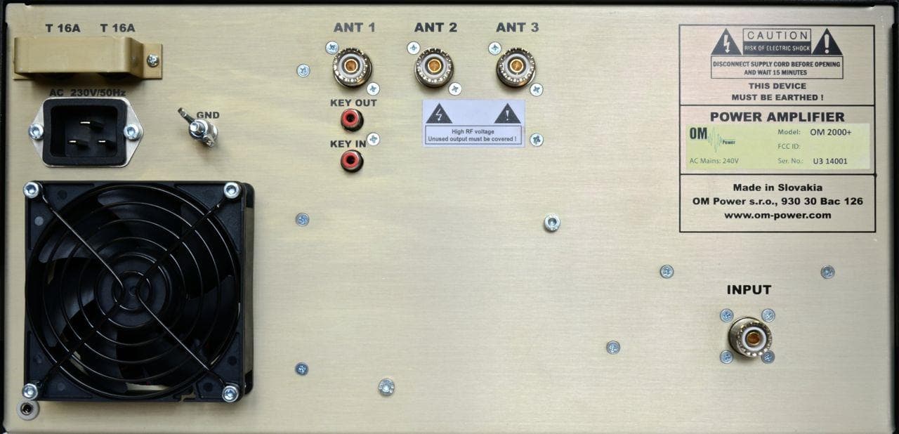
X8NX8NOM2000
Sep 08, 2014Amateur Radio Service Linear HF Amplifier
Equipment Class
AMP - Amplifier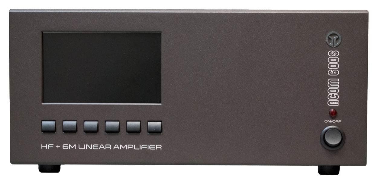
X8NA600S
Apr 29, 2014Amateur Radio Linear Amplifier
Equipment Class
AMP - Amplifier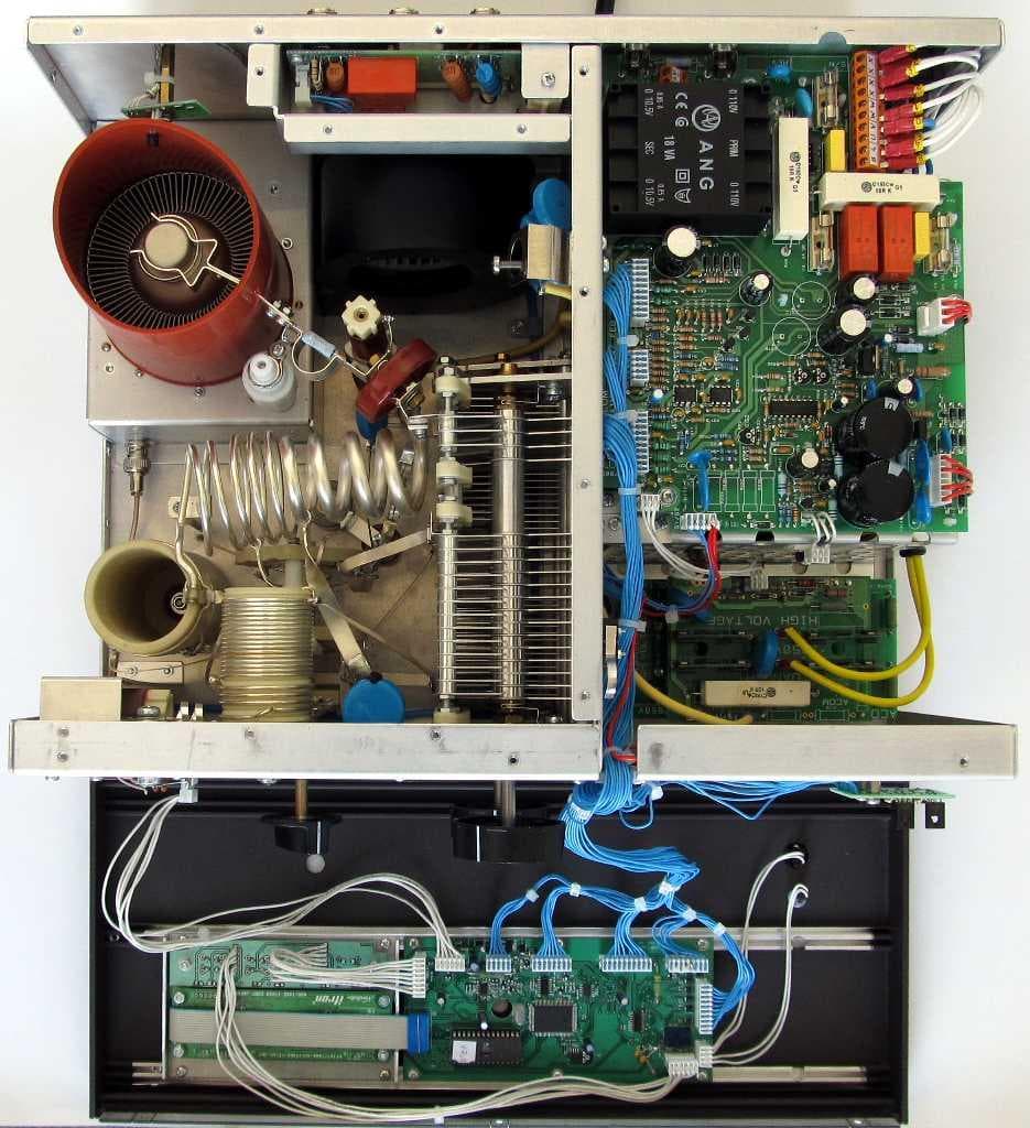
X8NX8NAA1500
Jun 06, 2012Amateur Radio Linear Amplifier
Equipment Class
AMP - Amplifier
X8NAA1011
May 02, 2010Amateur Radio RF Amplifier
Equipment Class
AMP - Amplifier