X8NX8NOM2000Amateur Radio Service Linear HF Amplifier
Array Solutions dba Array Solutions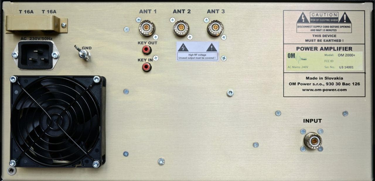
Click to zoom
Application Details
- Equipment Class
- AMP - Amplifier
- Date of Grant
- Sep 08, 2014
- Application Purpose
- Original Equipment
- Date of Application
- Jun 16, 2014
- Equipment Note
- Amateur Radio Service Linear HF Amplifier
- Frequency Range
- 1.80000000 - 54.00000000
- Country
- United States
Documents & Files
Document Text
Text extracted from the exhibit documents filed with the FCC. Open a document above to read the original.
Users Manual
Exhibit 6 Page 1 from 35 Exhibit 6: User’s Manual External Radio Frequency Power Amplifier OM2000+ Model 2000+ Array Solutions 2611 North Beltline Rd Suite 109 Sunnyvale, Texas 75182 USA Tel: 214 954 7140 fax: 214 954 7142 E-mail: [email protected] Exhibit 6 Page 2 from 35 TABLE OF CONTENTS 1. GENERAL INFORMATION ..................................................................... 4 2.1. Introduction ............................................................................ 4 2.2. Specification ............................................................................ 4 2.2.1. Parameters ............................................................................ 4 2.2.2. Protection Circuits ............................................................................ 4 2.2.3. Indicators ............................................................................ 5 2.2.4. Features ............................................................................ 5 2. SAFETY INSTRUCTIONS ............................................................................ 6 3. GENERAL DESCRIPTION ............................................................................ 7 3.1. HF part ............................................................................ 7 3.2. Power Supply ............................................................................ 8 3.3. Safety Devices ............................................................................ 9 4. INSTALLATION ............................................................................ 9 4.1. Grounding ............................................................................ 10 4.2. Coaxial Cable ............................................................................ 10 4.3. Control Cable ............................................................................ 10 4.4. Main Supply ............................................................................ 11 4.5. Cooling ............................................................................ 11 5. OPERATION ............................................................................ 12 5.1. Operation Elements ............................................................................ 12 5.2. Preparation for operation ......................................................................... 14 5.2.1. Display menu ............................................................................ 15 5.2.2. Settings menu ............................................................................ 17 5.2.3. Service menu ............................................................................ 19 5.3. Operation mode ............................................................................ 22 5.4. Tuning of the Power Amplifier ............................................................... 24 6. MAINTENANCE ............................................................................ 28 6.1. Indication of Fault Conditions ............................................................... 28 Exhibit 6 Page 3 from 35 6.2. Fuse Replacement ............................................................................ 31 6.3. Tube Replacement ............................................................................ 31 6.4. Cleaning ............................................................................ 31 7. APPENDIX ............................................................................ 32 7.1. Primary AC selection ............................................................................ 32 7.2. Removing the HV Transformer ............................................................. 33 7.3. Block Diagram of the OM2000+ Power Amplifier .............................. 35 Exhibit 6 Page 4 from 35 1. GENERAL INFORMATION 1.1. Introduction he OM Power model OM2000+ is designed for all short wave amateur bands from 1.8 to 29.7 MHz (including WARC bands) plus 50 MHZ and all modes. It is equipped with a ceramic tetrode FU-728F. 1.2. Specification 1.2.1. Parameters Frequency Coverage Amateur Bands 1.8 – 29.7 MHz including WARC + 50 MHz Power Output 1500 W in SSB/CW on HF bands, 1500 W in CW/SSB on 6m 1500 W in RTTY Input Power Usually 70W for full Output Power Input Impedance 50 Ohm, VSWR < 1.5 : 1 Power Gain 15 dB Output Impedance 50 Ohm unbalanced Maximum Output SWR 2 : 1 SWR protection Automatic switching to STBY, when reflected power is 250W or higher Intermodulation distortion 32dB below nominal output Suppression of harmonics < -50 dBc Tubes FU-728F Ceramic tetrode Cooler Centrifugal blower + Axial blower Power supply Switchable 220V, 230V, 240V, 50/60 Hz Transformers One toroidal transformer 3kVA Dimensions 15,4“ x7,7” x 14,6” (width x height x depth) Weight 24 kg / 52 lbs 1.2.2. Protection Circuits There are several protection circuits used in the amplifier. They are activated when one or more of next parameters exceed defined values or some unwanted occasion occurs. VSWR too high Anode current too high Anode voltage error Screen current too high Screen voltage error T Exhibit 6 Page 5 from 35 Grid current too high Grid voltage error Heating voltage error Mistuning of PA Temperature to high Soft start for fuses protection “switch-on blocking “ at opened amplifier 1.2.3. Indicators Number of indicators visible on the front panel will inform you about value of some parameters or operation status: OLED display 4 x 20 characters Analog Wattmeter Double system meter for forward and reflected power measuring LED Indicators ON AIR – amplifier in transmitting mode STBY – standby mode FAULT – failure, switching off for abt. 4 sec ON – ON status 1.2.4. Features Manufacturer implemented some of the company’s current development results with most wanted operating and safety features into this new model: High level of protections Antenna switch for 3 different antennas Memory for faults and warnings, easy maintenance Automatic set-up anode current…
Text truncated - open the document above for the full version.
Users Manual
!!! Exhibit!6!!!!!!!!!!!!!!!!!!!!!!!!!!!!!!!!!!!!!!!!!!!!!!!!!!!!!!!Page!1!!from!35! ! Exhibit'6:'User’s'Manual' External)Radio)Frequency) Power)Amplifier)OM2000+) ) Model)2000+) ! Array%Solutions% 2611%North%Beltline%Rd%% Suite%109% Sunnyvale,%Texas%75182% USA% Tel:%214%954%7140% fax:%214%954%7142% % E-mail: [email protected] !!! Exhibit!6!!!!!!!!!!!!!!!!!!!!!!!!!!!!!!!!!!!!!!!!!!!!!!!!!!!!!!!Page!2!!from!35! ! TABLE%OF%CONTENTS% ! 1. GENERAL!INFORMATION!.....................................................................!4! 2.1.!Introduction!!............................................................................!4! 2.2.!Specification!!............................................................................!4! !!!!2.2.1.!!!!!!Parameters!!............................................................................!4! !!!!2.2.2.!!!!!!Protection!Circuits!............................................................................!4! !!!!2.2.3.!!!!!!Indicators!!............................................................................!5! !!!!2.2.4.!!!!!!Features!!............................................................................!5! ! 2. SAFETY!INSTRUCTIONS!!............................................................................!6! ! 3. GENERAL!DESCRIPTION!!............................................................................!7! 3.1. !HF!part!!!............................................................................!7! 3.2. !Power!Supply!!............................................................................!8! 3.3. !Safety!Devices!!............................................................................!9! ! 4. INSTALLATION!!!............................................................................!9! 4.1. !Grounding!!............................................................................!10! 4.2. !Coaxial!Cable!!............................................................................!10! 4.3. !Control!Cable!!............................................................................!10! 4.4. !Main!Supply!!............................................................................!11! 4.5. !Cooling!!!............................................................................!11! ! 5. OPERATION!!!............................................................................!12! 5.1. !Operation!Elements!............................................................................!12! 5.2. !Preparation!for!operation!!!.........................................................................!14! 5.2.1. Display!menu!............................................................................!15! 5.2.2. Settings!menu!............................................................................!17! 5.2.3. Service!menu!............................................................................!19! 5.3. !Operation!mode!............................................................................!22! 5.4. !Tuning!of!the!Power!Amplifier!!...............................................................!24! ! 6. MAINTENANCE!!!............................................................................!28! 6.1. !Indication!of!Fault!Conditions!!!...............................................................!28! !! !!! Exhibit!6!!!!!!!!!!!!!!!!!!!!!!!!!!!!!!!!!!!!!!!!!!!!!!!!!!!!!!!Page!3!!from!35! ! 6.2. !Fuse!Replacement!............................................................................!31! 6.3. !Tube!Replacement!............................................................................!31! 6.4. !Cleaning!!............................................................................!31! ! 7. APPENDIX!!!............................................................................!32! ! 7.1. !Primary!AC!selection!............................................................................!32! 7.2. !Removing!the!HV!Transformer!!!.............................................................!33! 7.3. !Block!Diagram!of!the!OM2000+!Power!Amplifier!!!..............................!35! ! ! ! ! ! !!! Exhibit!6!!!!!!!!!!!!!!!!!!!!!!!!!!!!!!!!!!!!!!!!!!!!!!!!!!!!!!!Page!4!!from!35! ! 1. GENERAL%INFORMATION% ) 1.1. Introduction' ) he!OM!Power!model!OM2000+!is!designed!for!!all!short!wave!amateur!bands!from!1.8!to!29.7!MHz! (including!WARC!bands)!!plus!50!MHZ!and!all!modes.!!It!is!equipped!with!a!ceramic!tetrode!!!!!!!!!!! FUa728F.) ! ! 1.2. ''Specification' 1.2.1. ''Parameters' ) )Frequency!Coverage!!Amateur!Bands!1.8!–!29.7!MHz!including!WARC!+!50!MHz! !Power!Output!!!1500!W!in!SSB/CW!on!HF!bands,!1500!W!in!CW/SSB!on!6m! !!!!!1500!W!in!RTTY! !Input!Power!!!Usually!70W!for!full!Output!Power! !Input!Impedance!!50!Ohm,!VSWR!<!1.5!:!1! !Power!Gain!!!15!dB! !Output!Impedance!!50!Ohm!unbalanced! !Maximum!Output!SWR!!2!:!1! !SWR!protection!!!Automatic!switching!to!STBY,!when!reflected!power! !!!!!is!250W!or!higher! !Intermodulation!distortion!32dB!below!nominal!output! !Suppression!of!harmonics!<!a50!dBc! !Tubes!!!!FUa728F!Ceramic!tetrode! !Cooler!!!!Centrifugal!blower!+!Axial!blower! !Power!supply!!!Switchable!220V,!230V,!240V,!50/60!Hz! !Transformers!!!One!toroidal!transformer!3kVA! !Dimensions!!!15,4“!x7,7”!x!14,6”!(width!x!height!x!depth)! !Weight!!!!24!kg!/!52!lbs! ! ! 1.2.2. Protection'Circuits' !There!are!several!protection!circuits!used!in!the!amplifier.!They!are!activated!when!one!or! !more!of!next!parameters!exceed!defined!values!or!some!unwanted!occasion!occurs.! • VSWR!too!high! • Anode!current!too!high! • Anode!voltage!error! • Screen!current!too!high! • Screen!voltage!error! T! !!! Exhibit!6!!!!!!!!!!!!!!!!!!!!!!!!!!!!!!!!!!!!!!!!!!!!!!!!!!!!!!!Page!5!!from!35! ! • Grid!current!too!high! • Grid!voltage!error! • Heating!voltage!error! • Mistuning!of!PA! • Temperature!to!high! • Soft!start!for!fuses!protection! • “switchaon!blocking!“!at!opened!amplifier! ! ! 1.2.3. Indicators' !!Number! of! indicators! visible! on! the! front! panel! w…
Text truncated - open the document above for the full version.
Attestation Statements
Exhibit 9 Page 1 of 4 Exhibit 9: Additional Information in Response to 47 CFR Ch.1 Sec. 2.1033 External Radio Frequency Power Amplifier OM2000+ Model 2000+ Array Solutions 2611 North Beltline Rd Suite 109 Sunnyvale, Texas 75182 USA Tel: 214 954 7140 fax: 214 954 7142 E-mail: [email protected] Exhibit 9 Page 2 of 4 Additional Information in Response to 47 CFR Ch.1 Sec. 2.1033 Section c.1. The "OM2000+” HF linear amplifier will be assembled and production testing performed in the Republic of Slovakia by the company “OM Power, Ltd”. OM Power, Ltd. Was founded and started production external radio frequency power amplifiers for amateur use since 2003. The company has designed and manufactured the following types of amplifiers: - the "OM2500 HF" HF Linear Amplifier accepted as FCC ID: X8NX8NOM2500A which was marketed in the United States by Array Solutions ltd. Inc. of Sunnyvale, Texas ,USA continuously till now; - the "OM2500A” Automatic HF Linear Amplifier accepted as FCC ID: X8NX8NOM2500A, which is in volume production and is being presently marketed in the United States by the Applicant; OM Power, Ltd is located at Báč 126, ZIP 93030, Slovakia. The president and principal owner of OM Power, Ltd is Mr. Tibor Ferenec. Applicant for certification, Array Solutions is a distributor of OM Power, Ltd products in North America. With respect to the subject, "OM2000+” HF linear amplifier equipment, Applicant is responsible for all aspects of quality assurance, marketing and service in USA, as well as for the compliance with FCC rules. Array Solutions is located at 2611 North Beltline Rd, Suite 109, Sunnyvale, Texas 75182, USA. Applicant has conducted or observed all design proof testing and will re-tested samples of production equipment on an ongoing basis to assure conformance to Applicant's quality standards, including all FCC regulatory requirements. Section c.2 This product designated "OM2000+ HF linear amplifier”, hereafter "OM2000+", is an external radio frequency power amplifier that covers all amateur bands from 1.8 through 54MHz and provides 1500W PEP output power with typically 70W-exciter drive, or 1500W continuous carrier. It is based on and is similar to our previous model OM2500HF (FCC ID: X8NX8NOM2500A) but uses more popular tube. The OM2000+ will be marketed in the United States for use in the Amateur Radio Service. The FCC identifier for the OM2000+ will be X8NOM2000 Section c.3 A copy of the Installation and Operating Instructions for the OM2000+ is included as Exhibit 6. Section c.4 The equipment is suitable for all types of emission authorized for amateur HF use in 97.305 of FCC rules. Exhibit 9 Page 3 of 4 Section c.5 The equipment is designed to meet all specifications and FCC performance standards on all amateur bands from 1.8 to 54MHz. When delivered to any buyer within FCC's jurisdiction, the equipment is not operable on frequencies between 26MHz and 28MHz according to FCC 97.317(b). Section c.6 The equipment can be operated at any power level up to 1500W continuous carrier. Lower power linear operation is possible by reducing RF excitation proportionately. An analog and digital peak-reading meter is provided for direct readout of output forward peak-power at any time. The numeric value of the output power can be read on the display too. Section c.7 The equipment is rated for maximum RF power output of 1500W continuous carrier. Section c.8 Nominal voltages and currents at rated output (1500W) are: DC plate voltage: 2800V DC plate current: 0.9A DC screen voltage: 325V DC screen current: 0mA DC grid bias: -65V (adjusted individually for 350mA idling plate current). Section c.9 Tune-up procedure is simplified by a TUNE bargraph which helps the operator to quickly and precisely match antennas and eliminates probability of inadvertent mistune. The antenna impedance matching capability is up to VSWR 3:1 or higher. The procedure description is included in Exhibit 11, as well as in the Operating Manual - Exhibit 6, Section 5.4. Section c.10 Several features of the OM2000+ design are specifically intended to reduce spurious radiation to a minimum. In the input circuit, a non-inductive resistor load ensures that VSWR of 1.2:1 or less is presented to the exciter at the RF input terminal over the entire frequency range. The output circuit comprises a classic Pi-L network, which suppresses the harmonic emissions. Results of our OM2000+ performance tests are included in Exhibit 5. RF performance and spurious emissions are generally the same as that of "OM2500HF", “OM2500A”. Section c.11 A photograph showing the design of the FCC identification label for the OM2000+ is included as Exhibit 1. Section c.12 Photographs showing the construction and layout of the OM2000+ are included as Exhibits 2 and Exhibit 7. Exhibit 9 Page 4 of 4 Section c.13 Not applicable to external RF power amplifies. Section c.14 Not applicable, as provided in Section c.15. Section c.15 Measurement data indicating compliance with requirements of Part 97.307 and Part 97.317 is included as Exhibits 5 and 10. Section c.16 Not applicable to external RF power amplifiers. Section c.17 Not applicable to external RF power amplifiers. The subject equipment application is not part of a composite system. John D Terleski Array Solutions - President
Attestation Statements
Exhibit 10 Page 1 of 3 Exhibit 10: Measurements Demonstrating Conformance to 97.307 and 97.317 External Radio Frequency Power Amplifier OM2000+ Model 2000+ Array Solutions 2611 North Beltline Rd Suite 109 Sunnyvale, Texas 75182 USA Tel: 214 954 7140 fax: 214 954 7142 E-mail: [email protected] Exhibit 10 Page 2 of 3 Measurements Demonstrating Conformance to 97.307 and 97.317 97.317(a)(1)(2)&(3) & 97.317(b). Spurious Emissions per 97.307(d) and Gain versus Frequency. Results reflect amplifier as shipped with 26 to 28MHz Bands disabled. Amplifier under test operated at frequency f1 with CW (A1A) excitation. Spectrum analyzer with a 20dB input attenuator was used to observe all frequencies, from f1 through at least 10f1 for harmonic and spurious emissions. Power Gain per 97.317 Spurious Emmisions per 97.307d Frequency f1, MHz Input Power, W Output Power, W Amplifier Gain, dB 2f1, dBc 3f1, dBc 4f1, dBc 5-10f1, dBc worst case 1,850 75 1500 13,01 51,7 75,0 82,1 85,0 3,750 72 1500 13,19 50,6 76,1 81,9 85,0 7,150 70,5 1500 13,28 58,3 81,8 81,1 85,0 10,125 72 1500 13,19 58,7 81,7 82,1 85,0 14,175 70 1500 13,32 61,8 82,1 85,0 85,0 18,100 69 1500 13,37 62,9 76,1 81,2 85,0 21,225 65,3 1500 13,61 64,5 80,4 81,3 85,0 24,930 58,5 1500 14,09 54,5 72,1 81,5 85,0 28,500 51,8 1500 14,62 64,7 71,0 76,1 80,0 50,200 63,4 1500 13,74 58,2 55,5 73,1 80,0 Amplifier was not capable of operation on any frequency or frequencies between 26 and 28MHz as measured at the points below per 97.317-(a) (3). 26,000 50 49,1 -0,08 27,000 50 49,0 -0,09 28,000 50 48,9 -0,10 Exhibit 10 Page 3 of 3 97.307(a)(b). Intermodulation & Linearity Exciter operating in SSB mode with two equal-tone audio applied to the microphone input. Amplifier under test driven to 1500W PEP output at the center of the band with 70W PEP input power. 97.317(a)(1). When the amplifier is in the “standby” or “off” positions, but still connected to the exciter, no measurable spectrum change from the normal output of the exciter is detectable with the spectrum analyzer (noise floor approximately –115dBc) when amplifier is driven with 0 to 150 W mean RF power. 97.317(b). The amplifier possesses none of the prohibited characteristics listed in this section. 97.317(a)(2). The amplifier gain does not exceed 15 dB for any level of input signal. Additional data: Information and data supplied by tube manufacturer concerning FU-728F tetrode is available by request from the manufacturer. John D Terleski Array Solutions - President Inter-modulation in dB relative to 1500W PEP per 97.307(a)(b) Order: D3 D5 D7 D9 D11 and higher Freq. MHz dB dB dB dB dB 14,200 -34,2 -47,8 -55,1 -60,6 -62
Block Diagram
Exhibit 3 page 1 of 2 Exhibit 3: Block Diagram External Radio Frequency Power Amplifier OM2000+ Model 2000+ Array Solutions 2611 North Beltline Rd Suite 109 Sunnyvale, Texas 75182 USA Tel: 214 954 7140 fax: 214 954 7142 E-mail: [email protected] Exhibit 3 page 2 of 2 Block Diagram J4 J12 J3 Ext. blower J10 ! J8 K1 K6 CONTROL BOARD DISPLAY ANT SWITCH K2 K1 K1 J3 A3 A2 A1 K3 K7 K2 K1 K11 K4 K8 J3 J2 J1 K3 J1 J11 K1 K2 J15 J14 J8 J9 J7 J2 J13 AC IN J4 24V Rev.: 10.2.2014 K2 K1 Cover SW OM 2000+ block diagram L8 L7 SW 1c SW 1b SW 1a FU728f Rele GS KEY IN KEY OUT TR 1 Blower ON SW ON BOARD HV SUPPLY METER BOARD OUTPUT AC INPUT PWR METER SCREEN BOARD INPUT BOARD 1 R1 2 1 47 C2 2 1 1 L10 2 1 L6 2 T 16A 2 1 1 1 F 4 A F 3 2 1 1 2 T 16A 2 1 2 1 3 2 1 K1 2 1 1 4 5 3 1 2 1 L4 2 2 1 2 1 2 1 2 1 2 1 2 1 2 1 2 1 2 1 2 1 2 1 2 1 2 1 2 1 1 2 1 2 2 1 1 2 1 2 1
Block Diagram
Exhibit 3 page 1 of 2 Exhibit 3: Block Diagram External Radio Frequency Power Amplifier OM2000+ Model 2000+ Array Solutions 2611 North Beltline Rd Suite 109 Sunnyvale, Texas 75182 USA Tel: 214 954 7140 fax: 214 954 7142 E-mail: [email protected] Exhibit 3 page 2 of 2 Block Diagram J4 J12 J3 Ext. blower J10 ! J8 K1 K6 CONTROL BOARD DISPLAY ANT SWITCH K2 K1 K1 J3 A3 A2A1 K3 K7 K2 K1 K11K4K8 J3 J2J1 K3 J1 J11 K1 K2 J15 J14 J8 J9 J7 J2 J13 AC INJ4 24V Rev.: 7.8.2014 K2 K1 Cover SW OM 2000+ block diagram L8 L7 SW 1c SW 1b SW 1a FU728f Rele GS KEY IN KEY OUT TR 1 Blower ON SW ON BOARD HV SUPPLY METER BOARD OUTPUT AC INPUT PWR METER SCREEN BOARD INPUT BOARD 1 L11 2 1 R1 21 56C2 21 1 L10 2 1 L6 2 T 16A 2 1 11 F 4A F3 2112 T 16A 2 1 21 3 21 K1 2 1 1 45 3 12 1 L4 2 2 1 2 1 2 1 21 21 21 21 21 21 21 2 1 2 1 2 1 2 1 1212 2 11 2 1 2 1
Cover Letter(s)
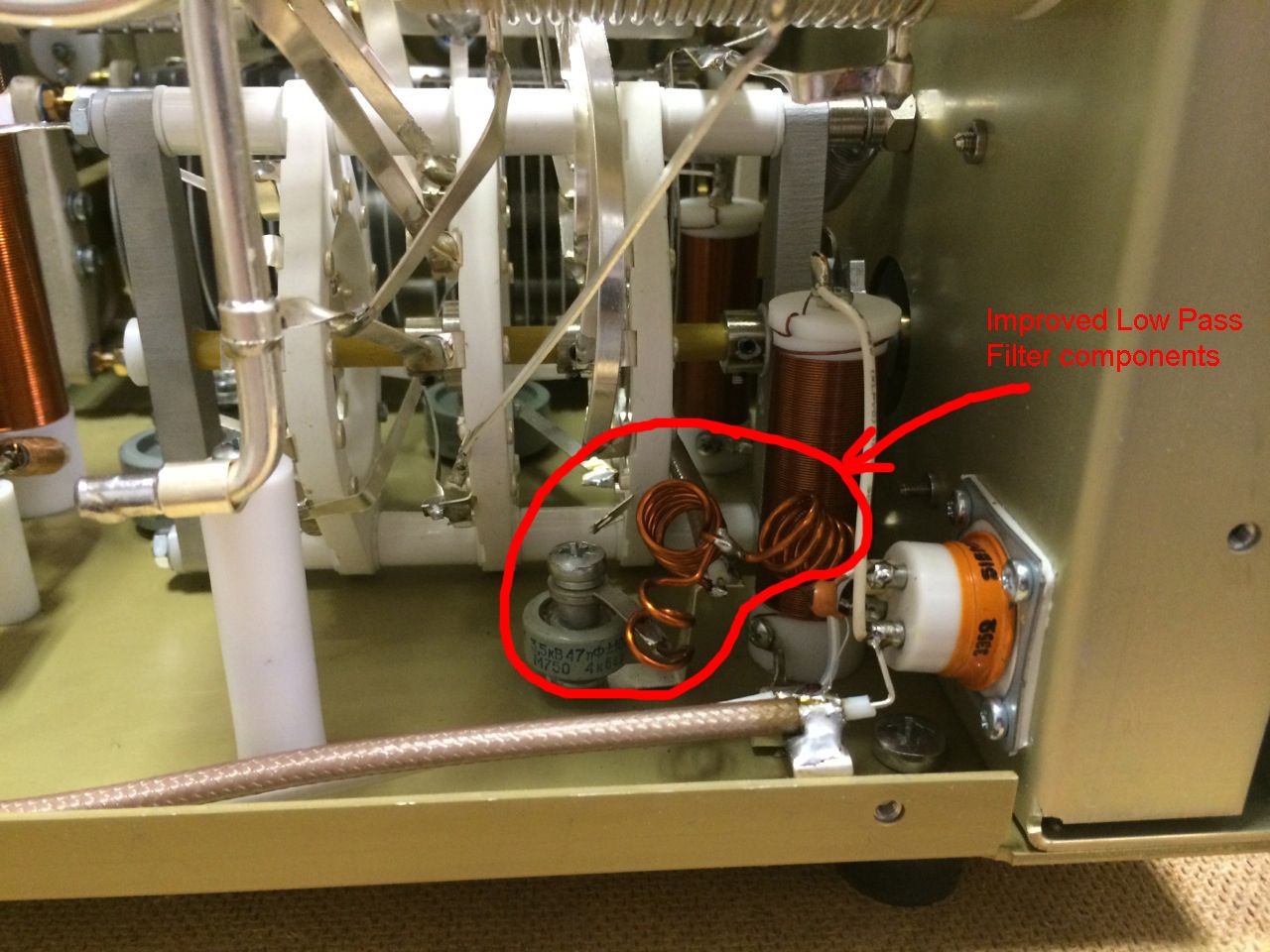
ARRAY SOLUTIONS 2611 N. Beltline Rd Suite 109 Sunnyvale, TX 75182 214 954 7140 office 214 954 7142 fax [email protected] Monday, August 11, 2014 To Inspecting EA Engineer, Thank you for pointing out our non-compliance to the 50Mhz specification of this OM2000+ amplifier. We have modified the output harmonic filter tank circuitry to more then meet the specification. All production units sold in the USA will have this added filtering. I am have uploaded the new measurement exhibits for your review. I attest these measurements are accurate. Best Regards, John Terleski President
External Photos
Exhibit 2 page 1 of 2 Exhibit 2: External Photos External Radio Frequency Power Amplifier OM2000+ Model 2000+ Array Solutions 2611 North Beltline Rd Suite 109 Sunnyvale, Texas 75182 USA Tel: 214 954 7140 fax: 214 954 7142 E-mail: [email protected] Exhibit 2 page 2 of 2 External Photos Fig.1. Front View Fig.2. Rear View
ID Label/Location Info
Exhibit 1 page 1 of 3 Exhibit 1: ID Label Location Info External Radio Frequency Power Amplifier OM2000+ Model 2000+ Array Solutions 2611 North Beltline Rd Suite 109 Sunnyvale, Texas 75182 USA Tel: 214 954 7140 fax: 214 954 7142 E-mail: [email protected] Exhibit 1 page 2 of 3 FCC ID and Label Location Information In compliance with FCC Regulation 47 CFR Ch. 1 part 2.925, the OM2000+, External Radio Frequency Power Amplifier, Model 2000+ bears a label located on the rear plate of the equipment which displays the following FCC Identifier: Part (a) 1. The term FCC ID followed by the three digit Grantee Code and the six digit Equipment Product Code. 2. Not applicable. 3. Not applicable. Part (b) Not applicable Part (c) Reserved Part (d) 1. The OM2000+ label is indelibly printed on the rear panel of the equipment. This label will last the lifetime of the equipment in the environment in which the equipment will be operated and is not readily detachable. 2. The OM2000+ label is readily visible on the outside of the equipment enclosure. Part (e) Not applicable. Part (f) 1. The size of the label is 2,5 by 0,8 inches. The label and its location on the equipment are shown in the following pictures. Fig.1. Label location Exhibit 1 page 3 of 3 Fig.2. The label The Serial Number consists of 7 digit, where the first two digits represent the model type and second two digits represent year of manufacture. In the FCC ID # Grantee code is: X8N and the OM2000 portion is the equipment product code.
Internal Photos
Exhibit 7 page 1 of 3 Exhibit 7: Internal Photos External Radio Frequency Power Amplifier OM2000+ Model 2000+ Array Solutions 2611 North Beltline Rd Suite 109 Sunnyvale, Texas 75182 USA Tel: 214 954 7140 fax: 214 954 7142 E-mail: [email protected] Exhibit 7 page 2 of 3 Fig.1. Right side View Fig.2. Left side View Exhibit 7 page 3 of 3 Fig.3. Top View (cover removed) Fig.5. Bottom View – Tube Deck (screen cover removed)
Operational Description
Exhibit 8 Page 1 of 2 Exhibit 8: Operational Description External Radio Frequency Power Amplifier OM2000+ Model OM2000+ Array Solutions 2611 North Beltline Rd Suite 109 Sunnyvale, Texas 75182 USA Tel: 214 954 7140 fax: 214 954 7142 E-mail: [email protected] Exhibit 8 Page 2 of 2 Operational Description The OM2000+ is a complete and self-contained linear amplifier that covers the amateur band 1.8-54MHz and provides 1500W output power with typically 70W-exciter drive. It is based on and is very similar to our previous model OM2500HF (FCC ID: X8NX8NOM2500A) but the final tube has been replaced by a more popular one. Look at the schematic diagrams (Exhibit 4). The high-performance ceramic-metal radial beam tetrode V1, type FU-728F, with a plate dissipation of 1200W, is grid-driven. It can dissipate up to 1200W when forced air cooled and is specifically designed for class AB1 RF linear amplifiers. The input signal from the RF INPUT jack is passed through a broadband input matching circuit (Input Board B), which comprises some components in the INPUT PCB and a 50 Ohm/250W RF swamping resistor. This circuit tunes out the tube input capacitance. The swamping resistor is not an attenuator but it is a termination load for this circuit. It could not be eliminated since a severe impedance mismatch to the driver would prevent using the amplifier at all. The nominal voltages and currents of the tubes at rated output power are as follows: DC plate voltage: 2800V DC plate current: 0.9A DC screen voltage: 325V DC screen current: 0mA DC grid bias: -65V (adjusted individually for 350mA idling plate current). The combination L1-R2 in the plate circuit is a VHF/UHF parasitic suppressor. DC plate voltage is fed through chokes L2,L3,L9 and the capacitor C4 blocks it from the output. The output circuit comprises L7, L8, C7-C13 which form a classic Pi-L network and suppress the harmonic frequency emissions. This tank is switched and tuned over the bands by ceramic switch SW1 and the air variable divided capacitors C8,C12 and C10,C13. The output signal is fed through an additional VHF low-pass filter for frequencies above 55MHz (L6, L10 and C2). Then it is passed through the vacuum antenna relay GS, wattmeter current transformer to the antenna switch and the three outputs. The choke L5 keep track of the antenna relay contact conditions and prevent the plate supply from reaching the antenna. L5 shunts the high voltage to ground should the DC blocking capacitor C4 fail. All supply voltages are delivered from Switch-On Board (small supply for control circuits, supply for control grid) and HV Supply Board (screen grid and plate voltage). The control grid, screen grid, and plate voltages and currents, plate cooling airflow temperature, forwarded and reflected power etc. are permanently monitored. Many software-derived protections are based on this information (Exhibit 6, part 1.2.2).
Parts List/Tune Up Info
Exhibit 11 Page 1 of 12 Exhibit 11: Tuning Procedure and Parts List External Radio Frequency Power Amplifier OM2000+ Model 2000+ Array Solutions 2611 North Beltline Rd Suite 109 Sunnyvale, Texas 75182 USA Tel: 214 954 7140 fax: 214 954 7142 E-mail: [email protected] Exhibit 11 Page 2 of 12 1.2. Tuning of the Power Amplifier The OM2000+ power amplifier is operated in class AB. Thus it’s possible to obtain a maximum output power at excellent linearity. For this purpose the amplifier has to be tuned carefully. CAUTION The operation of a mistuned PA will cause malfunctions, the increase of grid current and problems with TVI/BCI. CAUTION If the input power is higher than 10W and the power amplifier is NOT correctly tuned, the safety devices will switch it to STBY. After switching the amplifier to STBY, you need to switch it back to the OPER mode by pressing RESET button shortly. A tuning table is delivered with the power amplifier. For coarse tuning select a band with BAND switch and choose the setting of “TUNE” and “LOAD” capacitors according to the table. Band (MHz) Tune Load Input PWR (W) Output PWR (W) 1.845 70 45 75 1500 3.630 69 51 72 1500 7.050 50 90 71 1500 10.125 72 28 72 1500 14.175 69 40 70 1500 18.150 81 48 69 1500 21.230 47 67 65 1500 24.940 61 64 59 1500 28.450 33 76 52 1500 50.200 22 90 64 1500 NOTE Delivered tuning table was made for 50 Ohm loading of PA (dummy load). Each amplifier should have different values depending on used frequency and used type of antenna. Make your own table valid for your real conditions. There are two ways how to do fine tuning. The first method uses a gradual increase in the input power when tuning the PA (as most operators accustomed). In every case we recommend adjust the display for both of methods so it shows two parameters important for fine tuning - TUNE and Is graph (> l <). Exhibit 11 Page 3 of 12 Press OPER to enter operation mode. Apply low input power and press PTT. Be sure you selected right BAND, TUNE and LOAD knob positions. If you made some mistake, fault message appears: Safety circuit stopped transmitting, fault LED is ON (Fault code 4 is saving to the memory). Release PTT, set proper positions of BAND, TUNE and LOAD according to the table and press PTT again. Another mistake can occur, if you have antenna connected to the wrong output. In such a case „SWR is too high“ error message appears. Change antenna output using S4 button. This is not an optimal result, TUNE indicator must go between both arrows. Use TUNE knob to get maximum output power and LOAD knob to get indic…
Text truncated - open the document above for the full version.
Contact Information
Applicant
John Terleski(President)
Technical Specifications
| # | Rule Parts | Frequency Range | Power Output | Emission |
|---|---|---|---|---|
| 1 | 97 | 1.8 MHz - 54 MHz | 1500 W | A1A |
Other Applications from Array Solutions dba Array Solutions
X8NA600S
Apr 29, 2014Amateur Radio Linear Amplifier
Equipment Class
AMP - Amplifier
X8NX8NOM2500A
Dec 02, 2012Amateur Radio High Frequency Linear Amplifier
Equipment Class
AMP - Amplifier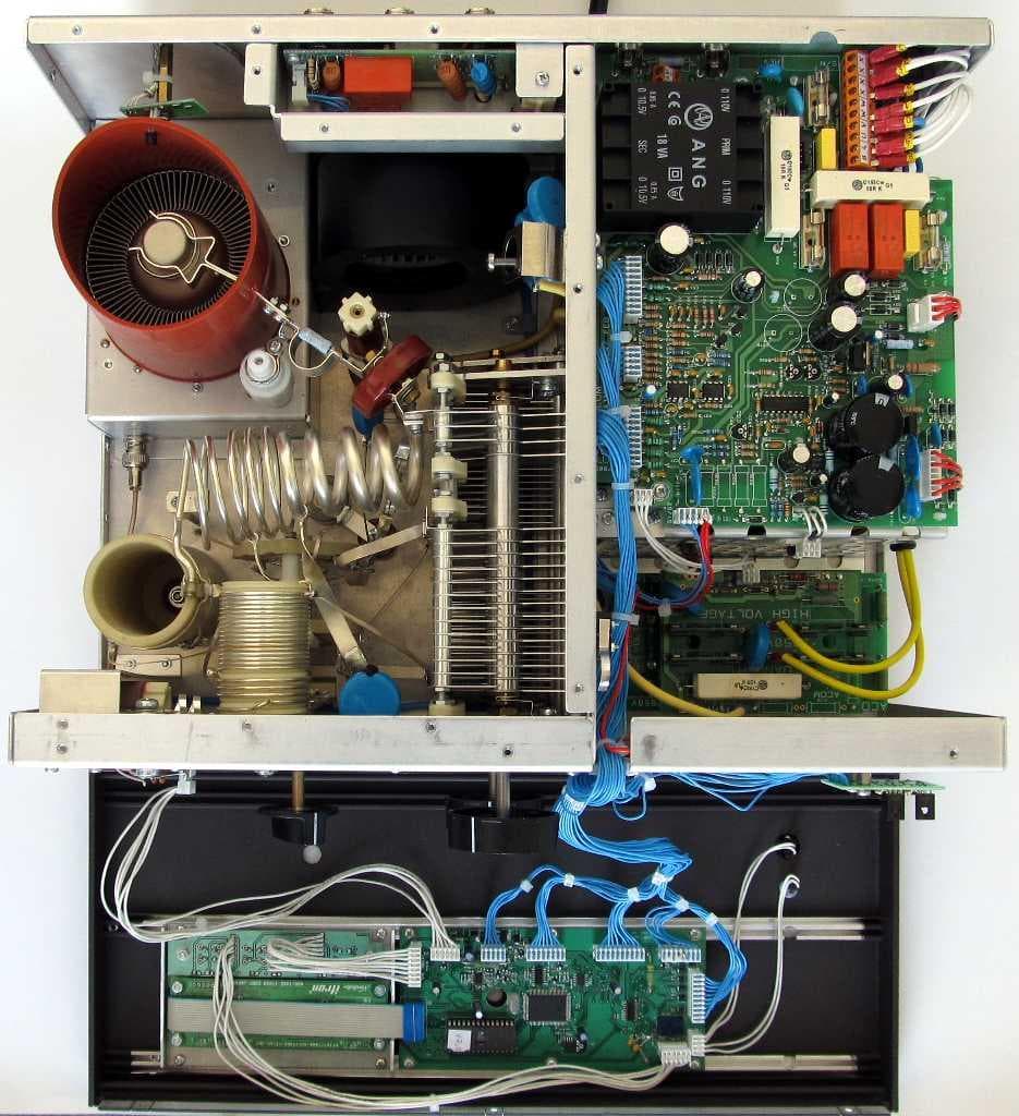
X8NX8NAA1500
Jun 06, 2012Amateur Radio Linear Amplifier
Equipment Class
AMP - Amplifier
X8NAA1011
May 02, 2010Amateur Radio RF Amplifier
Equipment Class
AMP - Amplifier