X8WC5626302.4 GHz Cordless Phone
Fanstel Corporation, Taipei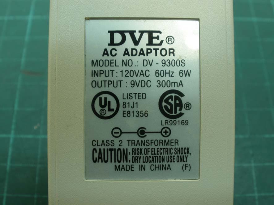
Click to zoom
Application Details
- Equipment Class
- DXX - Part 15 Low Power Communication Device Transmitter
- Date of Grant
- Apr 22, 2010
- Application Purpose
- Original Equipment
- Date of Application
- Apr 22, 2010
- Equipment Note
- 2.4 GHz Cordless Phone
- Frequency Range
- 2416.00000000 - 2471.00000000
- Company
- Fanstel Corporation, Taipei
- Country
- Taiwan
Documents & Files
Document Text
Text extracted from the exhibit documents filed with the FCC. Open a document above to read the original.
Users Manual
Using C5630(black), C5626(white) 2.4GHz Cordless Phone Version 2010003 to make or answer a call. to make or answer a call using speakerphone. to end a call. To redial the last number. O (Program): to program a number into memory button to dial the number stored in memory. ▲ After pressing button, to increase receiver volume and tone amplification. After pressing button, to increase speaker volume and tone amplification. ▼ After pressing button, to decrease receiver volume and tone amplification. After pressing button, to decrease speaker volume and tone amplification. Retain Amplification: LED light to indicate amplification settings are retained for future calls. Retain Amplification switch – set to On to save amplification level for future calls. Neckloop: a 3.5mm audio out jack. Headset: a 2.5mm jack for headset. Tone: set to Hi for extra high frequency amplification. Set to low for extra low frequency amplification. Ringer: to set ringer volume. Desk Mounting Plug one end of the 12 foot line cord into the jack labeled “ Line ” on the bottom of phone and plug the other end into a wall jack. The wall mount bracket is not recommended for desk top use. Wall Mounting Insert the wall mount bracket into two holes labeled “WALL” on the bottom of phone base. 1. Plug one end of the 7 inch line cord into the jack labeled “ Line ” on the bottom of phone and plug the other end into the jack on the wall plate. 2. Slip the mounting holes (one on wall mount bracket and one on rear edge of base) over the wall plate posts and firmly slide the unit into place. Charging batteries Pull the tab around handset battery compartment. Battery will make contact with charging circuit. Place the handset on the base unit for 6 hours before initial use. Optional Swappable Rechargeable Batteries Optional rechargeable batteries can be installed in the base unit. In case of commercial power failure, you can continue to make or receive phone calls. Duration of operat ion is limited by talk time and standby time. If you wish to use the handset when battery is low, you may swap the base batteries with the handset batteries. You can continue to make phone calls when batteries are recharged in the base . Retain Amplification Set the Retain Amplification switch to On ( Retain Amplification LED is lit), the receiver volume amplification level is saved automatically and used for all future calls. If the Retain Amplification switch is set to Off , receiver volume is reset when you replace the handset in the handset cradle. Adjusting Handset Receiver Volume To adjust the handset receiver volume during a phone call: 1. Press the ▲ button to increase the receiver volume 2. Press the ▼ button to decrease the receiver volume. 3. Stop adjustment when you can hear words most clearly. Warning: Excessive handset rece iver volume when the Retain Amplification LED is lit. Adjusting the Ringer Volume The "RINGER" switch on the right side of the phone and base controls the volume. You can set the "RINGER" switch to " Hi " for a high volume ring, " Low " for a low volume ring or " Off " to turn the ringer off. The Visual ringer flashes for all incoming calls regardless of the ringer setting. Programming the Memory Button You can program a telephone number into the button for one- touch speed dialing. 1. Press the O Program button. 2. Press the button. 3. Enter a telephone number 4. Press the O Program button again. Making a Call 1. Pick up the Handset and press the . If you wish to use speakerphone, press the button. 2. Using the Keypad , dial the desired telephone number. Receiving a Call 1. When you hear the phone ring, pick up the handset from the handset cradle and press the or the button. 2. When you are finished talkin g, replace the handset in the handset cradle or press the to end the call. Talkback Buttons and Audio Instructions When a button is pressed, it tal ks back. You can know a button is pressed incorrectly without looking. To disable talkback feature, press #OFF# or #633#. Phone announces “ talkback feature is off ”. To enable talkback feature, press #ON# or #66#. Phone announces “ talk back feature is on ”. To read out amplification setting, press ## , Phone announces, “Amplification setting is retained fo r future calls. Volume is set to level 6.” To read out basic operation instruction, press **. Important Safety Instructions Before using your telephone equipment, basic safety precautions should always be followed to reduce the risk of fire, electric shock and injury to persons, including the following: • Read and understand all instructions. • Follow all warnings and instructions marked on the product. • Unplug this product from the telephone jack and the power outlet before cleaning. Do not use liquid or aerosol cleaners. Use a damp cloth for cleaning. • Do not use this product near water, such as near a bathtub, sink, laundry tub, in a wet basement, or near a swimming pool. • Do not place this product on an unstable cart, sta nd, or table. Serious damage may result if the product falls. • Slots or openings in the cabinet and the back and bottom are provided for ventilation to protect the phone from overheating. These openings must not be blocked or covered. The product should never be placed near or over a radiator or heat register. • This product should be operated only from the type of power source indicated on the marking label. • Do not allow anything to rest on the power cord. Do not locate this product where the cord will be abused by persons walking on it. Do not attach the power cord to building surfaces. • Do not overload wall outlets and extension cords as this can result in the risk of fire or electric shock. • Never push any objects into this product through cabinet slots as they may touch dangerous voltage points or short out parts that could result in a fire or electric shock. Never spill liquid of any kind on the product. • If this product does not operate normally, see the “ In Case of Difficulty ” sec…
Text truncated - open the document above for the full version.
Cover Letter(s)
Confidentiality Letter Attention: Application Examiner Re: Request for confidentiality Applicant: FANSTEL Corporation, Taipei FCC ID: X8WC562630 To whom it may concern, Request is hereby submitted by FANSTEL Corporation, Taipei to withhold permanently from public review certain portions of the application for equipment certification for the referenced FCC identifiers. This request for confidentiality is made pursuant to 47 CFR 0.457(d) of the FCC Rules. In particular, the following sections of the application are to be kept permanently confidential: • Schematics • Detailed Block diagrams • Detailed Operational/Functional Description Rationale for request for confidentiality: FANSTEL Corporation, Taipei has invested considerable time and materials in research and development to produce the referenced product. Disclosure of the permanently confidential portions of this application to competitors would not only give them significant competitive advantages in developing similar products, but would also disclose successful implementation of unpublished, leading edge technology developed by us. If you have questions or need further information, please contact the undersigned. Sincerely, Title: Engineer Company name: FANSTEL Corporation, Taipei Date: 2010-03-10
Cover Letter(s)
Attestation for FCC Declaration of Conformity FCC ID: X8WC562630 Date: 2010-03-10 Please be notified that we, the undersigned, FANSTEL Corporation, Taipei declares that the product which bears the above FCC ID is also compliant with the FCC requirements for DoC. The test report number supporting the DoC is TS10020017- EME. Testing in regards to this report was done by Intertek Testing Services Taiwan Ltd., located at 11, Ln.275, Ko Nan 1st Street, Shiang-Shan District, Hsinchu 300 Taiwan, which has been accredited in accordance to all of the requirements of 47CFR 2.948 (d) and (e) of the FCC rules and KDB349827. Sincerely, Printed name: M. H. Lin Position: Engineer FANSTEL Corporation, Taipei Tel: 886-2-2698-9328 Fax: 886-2-2698-4813 Email: [email protected]
External Photos
External photo of EUT
ID Label/Location Info
FANSTEL CORPORATION MODEL C5626 : THIS UNIT COMPLIES WITH PART 68 OF THE FCC RULESUS 5FQW411BC562630IC : 4100A-C562630USE STANDARD JACK USOC RJ11C WREN 1 1B POWER 9V DC 300mA CONFORMS TO ANSI UL STD 60950CERTIFIED TOCAN CSA STD C22 2 NO 60950 1 : / :.: /. /..- FCC ID: X8WC562630 SN : 9700327 US C CM L I S T E D I N T E R T E K MADE IN CHINA This device complies with part 15 of the FCC Rules . operation is subject to the following two conditions 1 This device may not cause harmful interference and2 This device must accept any interference received including interference that may cause undesird operation : ()(), . Privacy of communications may not be ensured whenusing phone . 45mm 19mm 10mm 22mm 45 19mm * 22 10mm * This device complies with part 15 of the FCC Rules . operation is subject to the following two conditions 1 This device may not cause harmful interference and 2 This device must accept any interference received including interference that may cause undesird operation : () (), . Privacy of communications may not be ensured when using phone . FCC ID: X8WC562630US 5FQW411BC562630IC :4100A-C562630 : FANSTEL CORPORATION MODEL C5626 : THIS UNIT COMPLIES WITH PART 68 OF THE FCC RULES FCC ID: X8WC562630 IC : 4100A-C562630 USE STANDARD JACK USOC RJ11C W REN 1 1B POWER 9V DC 300mA CONFORMS TO ANSI UL STD 60950 CERTIFIED TO CAN CSA STD C22 2 NO 60950 1 / :.: /. /..- US 5FQW411BC562630 : SN : 9700327 US C CM L I S T E D I N T E R T E K MADE IN CHINA FCC ID: X8WC562630US 5FQW411BC562630IC :4100A-C562630 :
Internal Photos
Internal photo of EUT Antenna Antenna RF Module Antenna Antenna RF Module
Test Report
FCC ID. : X8WC562630 Report No.: TS10020018-EME Page 1 of 34 EMC TEST REPORT Report No. : TS10020018-EME Model No. : C5630, C5626 Issued Date : Mar. 12, 2010 Applicant: Fanstel Corporation, Taipei 10F-10, No. 79, Sec.1, Hsin-Tai-Wu Rd., Hsi-Chih, Taipei Hsien 221, Taiwan Test Method/ Standard: 47 CFR FCC Part 15.249 & ANSI C63.4 2003 Test By: Intertek Testing Services Taiwan Ltd. No. 11, Lane 275, Ko-Nan 1 Street, Chia-Tung Li, Shiang-Shan District, Hsinchu City, Taiwan It may be duplicated completely for legal use with the allowance of the applicant. It shall not be reproduced except in full, without the written approval of Intertek Laboratory. The test result(s) in this report only applies to the tested sample(s). The test report was prepared by: Sign on File Shirla Hsiao / Officer These measurements were taken by: Sign on File Rex Liao / Engineer The test report was reviewed by: Name Leon Cheng Title Engineer FCC ID. : X8WC562630 Report No.: TS10020018-EME Page 2 of 34 Table of Contents Summary of Tests ............................................................................................................. 3 1. General information...................................................................................................... 4 1.1 Identification of the EUT........................................................................................ 4 1.2 Additional information about the EUT ................................................................... 5 1.3 Antenna description ................................................................................................ 5 2. Test specifications.........................................................................................................6 2.1 Test standard ........................................................................................................... 6 2.2 Operation mode ...................................................................................................... 6 2.3 Test equipment........................................................................................................ 7 3. Radiated emission test .................................................................................................. 8 3.1 Operating environment ........................................................................................... 8 3.2 Test setup & procedure ........................................................................................... 8 3.3 Emission limit......................................................................................................... 9 3.3.1 Fundamental and harmonics emission limits ...................................................... 9 3.3.2 General radiated emission limits ......................................................................... 9 3.4 Radiated spurious emission test data .................................................................... 10 3.4.1 Measurement results: frequencies equal to or less than 1 GHz ......................... 10 3.4.2 Measurement results: frequency above 1GHz................................................... 12 3.4.3 Measurement results: Fundamental emission.................................................... 18 4. Radiated emission on the band edge FCC 15.209 ...................................................... 21 5. Conducted emission test FCC 15.207 ........................................................................ 24 5.1 Operating environment ......................................................................................... 24 5.2 Test setup & procedure ......................................................................................... 24 5.3 Emission limit....................................................................................................... 24 5.4 Uncertainty of Conducted Emission..................................................................... 25 5.5 Conducted emission data FCC 15.207 ................................................................. 26 6. Calculation of Average Factor .................................................................................... 28 FCC ID. : X8WC562630 Report No.: TS10020018-EME Page 3 of 34 Summary of Tests Test Reference Results Radiated Emission test 15.249(a), (c), (d), 15.209 Pass Emission on the Band Edge 15.209 Pass Conducted Emission of AC Power 15.207 Pass Calculation of Average Factor 15.35 Pass FCC ID. : X8WC562630 Report No.: TS10020018-EME Page 4 of 34 1. General information 1.1 Identification of the EUT Product: 2.4GHz Cordless Phone Model No.: C5630 FCC ID.: X8WC562630 Frequency Range: 2416MHz ~ 2471MHz Channel Number: 12 channels Frequency of Each Channel: 2416 MHz + 5k MHz; k=0~11 Type of Modulation: ASK Rated Power: Handset: DC 3.6 V from NI-MH rechargeable battery Base unit: DC 9 V from adapter model: DV-9300S I/P Voltage: 120 Vac, 60 Hz Power Cord: N/A Data Cable: N/A Sample Received: Feb. 01, 2010 Test Date(s): Feb. 03, 2010~ Mar 03, 2010 Note 1: This report is for the exclusive use of Intertek's Client and is provided pursuant to the agreement between Intertek and its Client. Intertek's responsibility and liability are limited to the terms and conditions of the agreement. Intertek assumes no liability to any party, other than to the Client in accordance with the agreement, for any loss, expense or damage occasioned by the use of this report. Only the Client is authorized to permit copying or distribution of this report and then only in its entirety. Any use of the Intertek name or one of its marks for the sale or advertisement of the tested material, product or service must first be approved in writing by Intertek. The observations and test results in this report are relevant only to the sample tested. This report by itself does not imply that the material, product, or service is or has ever been under an Intertek certification program. Note 2: When determining the test conclusion, the Measurement Unce…
Text truncated - open the document above for the full version.
Test Setup Photos
Conducted Emission Test Set-up photo Radiated Emission Test set-up photo
Contact Information
Applicant
Paudy Tung(Engineer)
Test Firm
Intertek Testing Services Taiwan Ltd.Lily Shih
Technical Specifications
| # | Rule Parts | Frequency Range | Power Output |
|---|---|---|---|
| 1 | 15C | 2.42 GHz - 2.47 GHz | - |
Other Applications from Fanstel Corporation, Taipei
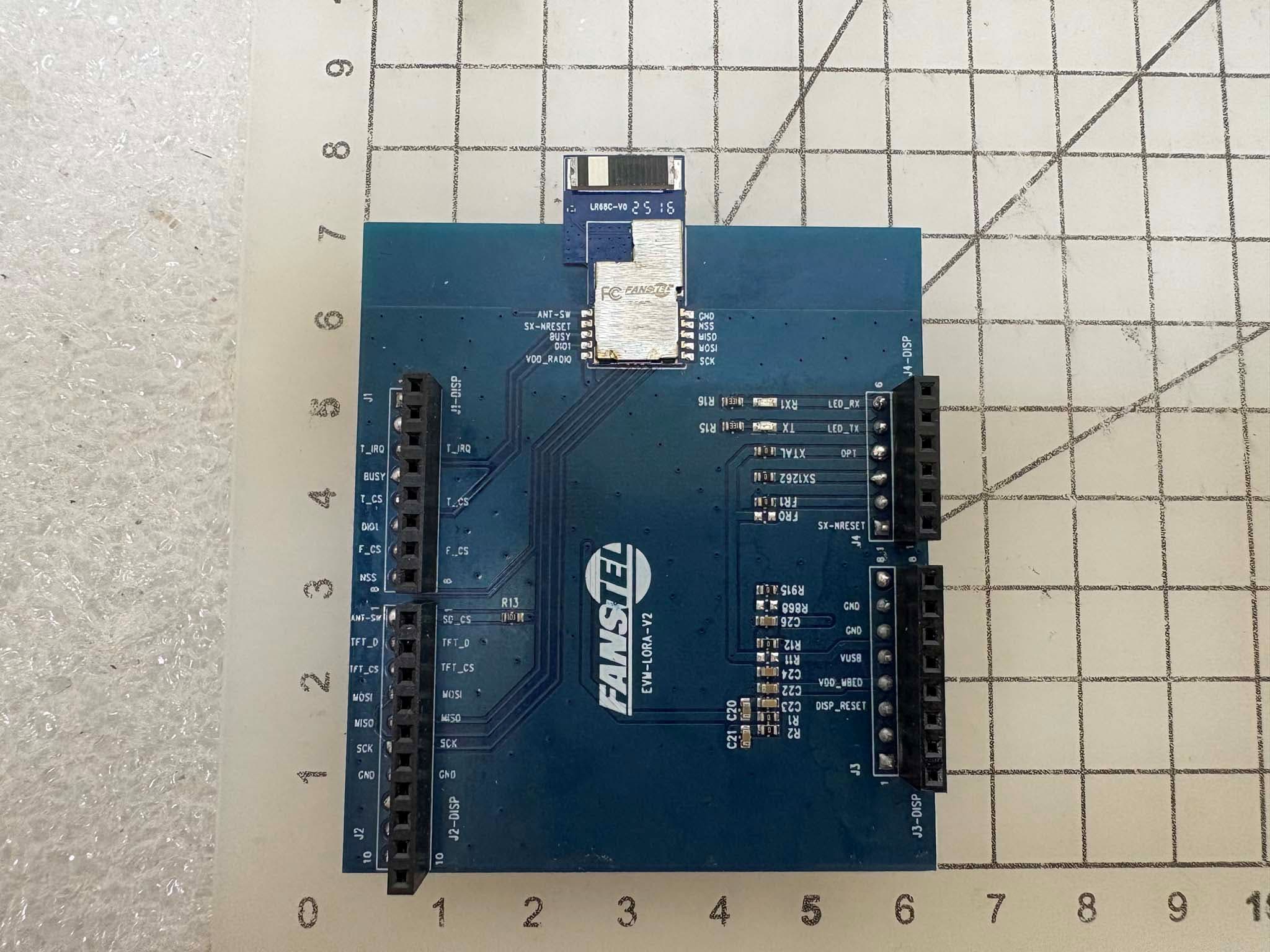
X8WLR68E
Dec 05, 2025LoRa transceiver Module
Equipment Class
DSS - Part 15 Spread Spectrum Transmitter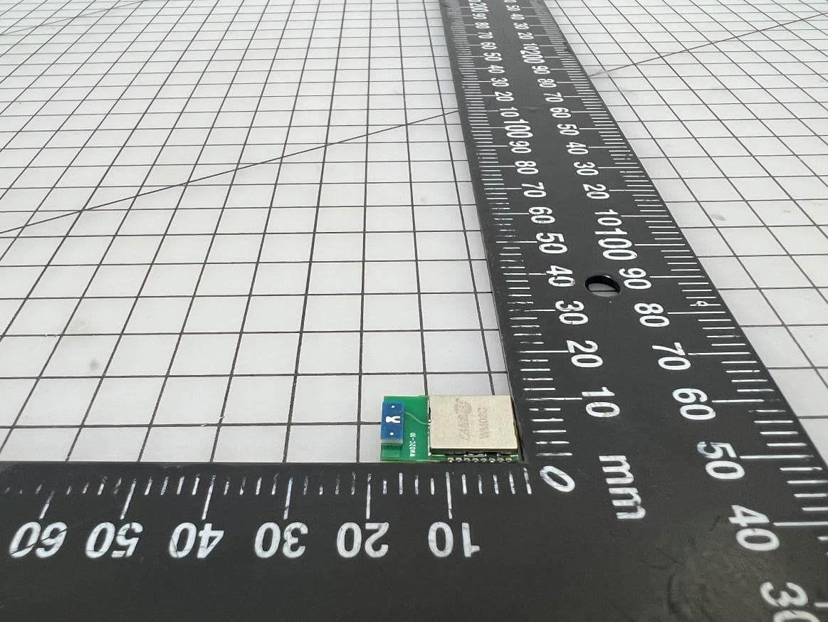
X8WWM02C
Sep 12, 2024WIFI 6 Module
Equipment Class
DTS - Digital Transmission System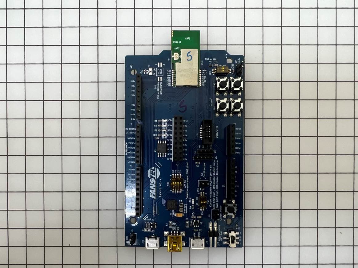
X8WBT40N
May 22, 2023Bluetooth 5.3, 802.15.4 module
Equipment Class
DTS - Digital Transmission System
X8WLR62XE
Mar 22, 2021Lora transceiver module
Equipment Class
DTS - Digital Transmission System
X8WBC833M
Jan 12, 2021Bluetooth 5.2 Module
Equipment Class
DTS - Digital Transmission System