X96882756Wireless Remote Control
Comeup Industries Inc.
Click to zoom
Application Details
- Equipment Class
- DXX - Part 15 Low Power Communication Device Transmitter
- Date of Grant
- May 10, 2015
- Application Purpose
- Original Equipment
- Date of Application
- May 10, 2015
- Equipment Note
- Wireless Remote Control
- Frequency Range
- 2402.00000000 - 2480.00000000
- Company
- Comeup Industries Inc.
- Country
- Taiwan
Documents & Files
Document Text
Text extracted from the exhibit documents filed with the FCC. Open a document above to read the original.
Users Manual
Wireless Receiver Model NO:882756 I.Specifications 1. Transmission range: 15 ~ 27 m (50 ~ 90 ft) 2. Receiver operation voltage: 8 - 24 V 3. Protection: IP 66 4. Operating temperature range: -20°C ~ +65°C III Operation 1. Install and replace battery. a. Remove the three screws from the wireless transmitter. b. Separate the top section and remove the old battery and dispose it. c. Insert new battery and join the top section with the bottom section. d. Make sure to fasten the three screws. 2. Start a. Attach the red(+) and black(-) battery leads to battery set on the vehicle. Press the Cutout switch , then the buzzer alarms for decoding and all LED flash. b. Hold the Power Button of the transmitter for about 5 seconds,then the LED Indicator lights permanently. c. Hold either Cable In Button or Cable Out Button of the transmitter, then the buzzer alarms long sound lasting for 5 seconds. d. Only flashing LED on Logo and Vehicle Battery Life.. e. The wireless remote control is now workable. 1. Cutout Switch Your Seal Gen2 9.5i/9.5si /9.5rsi Winches have a cutout switch to activate or deactivate the winch. The cutout switch on the Seal Gen2 9.5rsi models also deactivate the wireless receiver to prevent parasitic draw. 2. Vehicle Battery Life Your Seal Gen2 9.5i/9.5si/9.5rsi Winches indicate the status of vehicle battery level. The fan-shaped out Vehicle Battery Level indicate the status of your vehicle battery level by locating block and changing color。 If your battery level at an extreme low level, your must charge the battery immediately. The minimum requirement for a 12 V vehicle battery is 650 cold cranking amps。 1 st Icon (Green): Fully charged about 12V level 2 nd Icon (Green): Fair charged about 11V 3 rd Icon (Green): Fair charged about 10 V 4 th Icon (Green): Low charged about 9V 5 th Icon (Red): extreme low below 8V Wireless Remote Module Lithium Battery: CR2032 (3V) Cable OUT Cable IN Power Button LED Indicator IDB 1 3. Cable IN/OUT Direction Indicators: The green triangle icons on the Intelligence Dashboard (IDS) for your Seal Gen2 9.5rsi will light sequentially to indicate the rope winding direction。 3.1 Cable IN: The green triangle icons moved from the outside toward the center indicate the rope winding-in direction. 3.2 Cable OUT: The green triangles icons moved from the center toward the outside indicate the rope winding-out direction. 3.3 The green triangles icons will turn to red triangles if the motor is over-heating, but the direction remains unchanged. 4. Thermal Protection There are three kinds of thermal protection function to protect the motor and control from damaged or personal injury: 4.1 Temperature warning: The flashing red temperature icon on the intelligence Dashboard (IDB) of your Seal Gen2 9.5rsi winch indicates the motor is over-heating. 4.2 Handheld Remote Warning: The two green LED indicators on the wired remote control will change to the red if the motor is over-heating. 4.3 Buzzer warning:, The Seal Gen 2 9.5rs/9.5rsi/12.5rs include an audible buzzer alarm that alerts if the motor is over-heating. Temperature Warning Handheld Remote Warning Buzzer warning 5. Wireless Remote Control Icon 5.1 The intelligence Dashboard (IDB) of your Seal Gen2 9.5rsi includes a blue wireless signal icon that is continuously illuminated to confirm the wireless remote is paired with thewinch。 5.2 The solid green LED indicators on the wireless transmitter indicates goodsignal strength,but a flashing red LED indicates a weak signal。 6. Wireless transmitter’s battery life The solid green LED indicators on the wireless transmitter show a fair internal battery life, but a flashing green LED indicator indicates a low battery level。 The battery should be replaced immediately if a weak or no signal status found。 FEDERAL COMMUNICATIONS COMMISSION INTERFERENCE STATEMENT This equipment has been tested and found to comply with the limits for a Class B digital device, pursuant to part 15 of the FCC Rules。 These limits are designed to provide reasonable protection against harmful interference in a residential installation. This equipment generates uses and can radiate radio frequency energy and, if not installed and used in accordance with the instructions, may cause harmful interference to radio communications。 However, there is no guarantee that interference will not occur in a particular installation. If this equipment does cause harmful interference to radio or television reception, which can be determined by turning the equipment off and on, the user is encouraged to try to correct the interference by one or more of the following measures: - Reorient or relocate the receiving antenna. - Increase the separation between the equipment and receiver. - Connect the equipment into an outlet on a circuit different from that to which the receiver is connected. - Consult the dealer or an experienced radio / TV technician for help. CAUTION: Any changes or modifications not expressly approved by the grantee of this device could void the user's authority to operate the equipment。 CE Mark Warning • This is a Class B product, in a domestic environment, this product may cause radio interference, in which case the user may be required to take adequate measures。 FCC and Industry Canada (IC) Warning: • This device complies with Part 15 of the FCC Rules。 Operation is subject to the following two conditions: (1) This device may not cause harmful interference, and (2) this device must accept any interference received, including interference that may cause undesired operation。 2
External Photos
Report No.: 1510380R-RFUSP15V00 Page : 1 of 12 Attachment 2 : EUT Detailed Photographs (1) EUT Photo (2) EUT Photo
ID Label/Location Info
COMEUP INDUSTRIES INC. FCC ID.: X96882756 NO. 112, NANYANG ST., XIZHI DIST., NEW TAIPEI CITY 22152, TAIWAN Tel : +886-2-26947011 The FCC ID Label will be placed on the equipment as shown in the photograph below.
ID Label/Location Info
COMEUP INDUSTRIES INC. FCC ID.: X96882756 NO. 112, NANYANG ST., XIZHI DIST., NEW TAIPEI CITY 22152, TAIWAN Tel : +886-2-26947011 FCC ID Label
Internal Photos
Report No.: 1510380R-RFUSP15V00 Page : 2 of 12 (3) EUT Photo (4) EUT Photo Report No.: 1510380R-RFUSP15V00 Page : 3 of 12 (5) EUT Photo (6) EUT Photo Report No.: 1510380R-RFUSP15V00 Page : 4 of 12 (7) EUT Photo (8) EUT Photo Report No.: 1510380R-RFUSP15V00 Page : 5 of 12 (9) EUT Photo (10) EUT Photo Report No.: 1510380R-RFUSP15V00 Page : 6 of 12 (11) EUT Photo (12) EUT Photo Report No.: 1510380R-RFUSP15V00 Page : 7 of 12 (13) EUT Photo (14) EUT Photo Report No.: 1510380R-RFUSP15V00 Page : 8 of 12 (15) EUT Photo (16) EUT Photo Report No.: 1510380R-RFUSP15V00 Page : 9 of 12 (17) EUT Photo (18) EUT Photo -Module Antenna Report No.: 1510380R-RFUSP15V00 Page : 10 of 12 (19) EUT Photo (20) EUT Photo Report No.: 1510380R-RFUSP15V00 Page : 11 of 12 (21) EUT Photo (22) EUT Photo Report No.: 1510380R-RFUSP15V00 Page : 12 of 12 (23) EUT Photo
Test Report
Report No.: 1510380R-RFUSP15V00 Page: 1 of 44 FCC Test Report Product Name Wireless Remote Control Model No. 882756 FCC ID X96882756 Applicant COMEUP INDUSTRIES INC. Address NO. 112, NANYANG ST., XIZHI DIST., NEW TAIPEI CITY 22152, TAIWAN Date of Receipt Jan. 19, 2015 Issued Date April 15, 2015 Report No. 1510380R-RFUSP15V00 Report Version V1.0 The test results relate only to the samples tested. The test results shown in the test report are traceable to the national/international standard through the calibration report of the equipment and evaluated measurement uncertainty herein. This report must not be used to claim product endorsement by TAF or any agency of the government. The test report shall not be reproduced without the written approval of QuieTek Corporation. Report No.: 1510380R-RFUSP15V00 Page: 2 of 44 Test Report Issued Date: April 15, 2015 Report No.: 1510380R-RFUSP15V00 Product Name Wireless Remote Control Applicant COMEUP INDUSTRIES INC. Address NO. 112, NANYANG ST., XIZHI DIST., NEW TAIPEI CITY 22152, TAIWAN Manufacturer COMEUP INDUSTRIES INC. Model No. 882756 EUT Rated Voltage DC 8-24V EUT Test Voltage DC 12V (Power by battery) Trade Name COMEUP Applicable Standard FCC CFR Title 47 Part 15 Subpart C: 2014 ANSI C63.4: 2014, ANSI C63.10: 2013 Test Result Complied Documented By : ( Senior Adm. Specialist / Rita Huang ) Tested By : ( Engineer / Nova Chu ) Approved By : ( Director / Vincent Lin ) Report No.: 1510380R-RFUSP15V00 Page: 3 of 44 TABLE OF CONTENTS Description Page 1. GENERAL INFORMATION .....................................................................................................4 1.1. EUT Description............................................................................................................................4 1.2. Operational Description ................................................................................................................6 1.3. Tested System Datails....................................................................................................................7 1.4. Configuration of Test System ........................................................................................................7 1.5. EUT Exercise Software .................................................................................................................7 1.6. Test Facility ...................................................................................................................................8 2. Conducted Emission....................................................................................................................9 2.1. Test Equipment..............................................................................................................................9 2.2. Test Setup ......................................................................................................................................9 2.3. Limits ..........................................................................................................................................10 2.4. Test Procedure .............................................................................................................................10 2.5. Uncertainty ..................................................................................................................................10 2.6. Test Result of Conducted Emission.............................................................................................11 3. Radiated Emission .....................................................................................................................12 3.1. Test Equipment............................................................................................................................12 3.2. Test Setup ....................................................................................................................................13 3.3. Limits ..........................................................................................................................................14 3.4. Test Procedure .............................................................................................................................15 3.5. Uncertainty ..................................................................................................................................15 3.6. Test Result of Radiated Emission................................................................................................16 4. Band Edge ..................................................................................................................................29 4.1. Test Equipment............................................................................................................................29 4.2. Test Setup ....................................................................................................................................30 4.3. Limits ..........................................................................................................................................31 4.4. Test Procedure .............................................................................................................................31 4.5. Uncertainty ..................................................................................................................................31 4.6. Test Result of Band Edge ............................................................................................................32 5. Duty Cycle ..................................................................................................................................40 5.1. Test Equipment............................................................................................................................40 5.2. Test Setup ......................................................................................................…
Text truncated - open the document above for the full version.
Test Setup Photos
Report No.: 1510380R-RFUSP15V00 Page : 1 of 2 Attachment 1: EUT Test Setup Photographs Front View of Radiated Test Back View of Radiated Test Report No.: 1510380R-RFUSP15V00 Page : 2 of 2 Front View of Radiated Test (Horn) Back View of Radiated Test (Horn)
Contact Information
Applicant
Ben Huang(Director)
Test Firm
DEKRA TESTING AND CERTIFICATION CO., LTD.Warren Lin
Technical Specifications
| # | Rule Parts | Frequency Range | Power Output |
|---|---|---|---|
| 1 | 15C | 2.40 GHz - 2.48 GHz | - |
Other Applications from Comeup Industries Inc.

X96884242
Jan 02, 2023Wireless Remote Control
Equipment Class
DTS - Digital Transmission System
X96884212
Jan 02, 2023Wireless Remote Control
Equipment Class
DTS - Digital Transmission System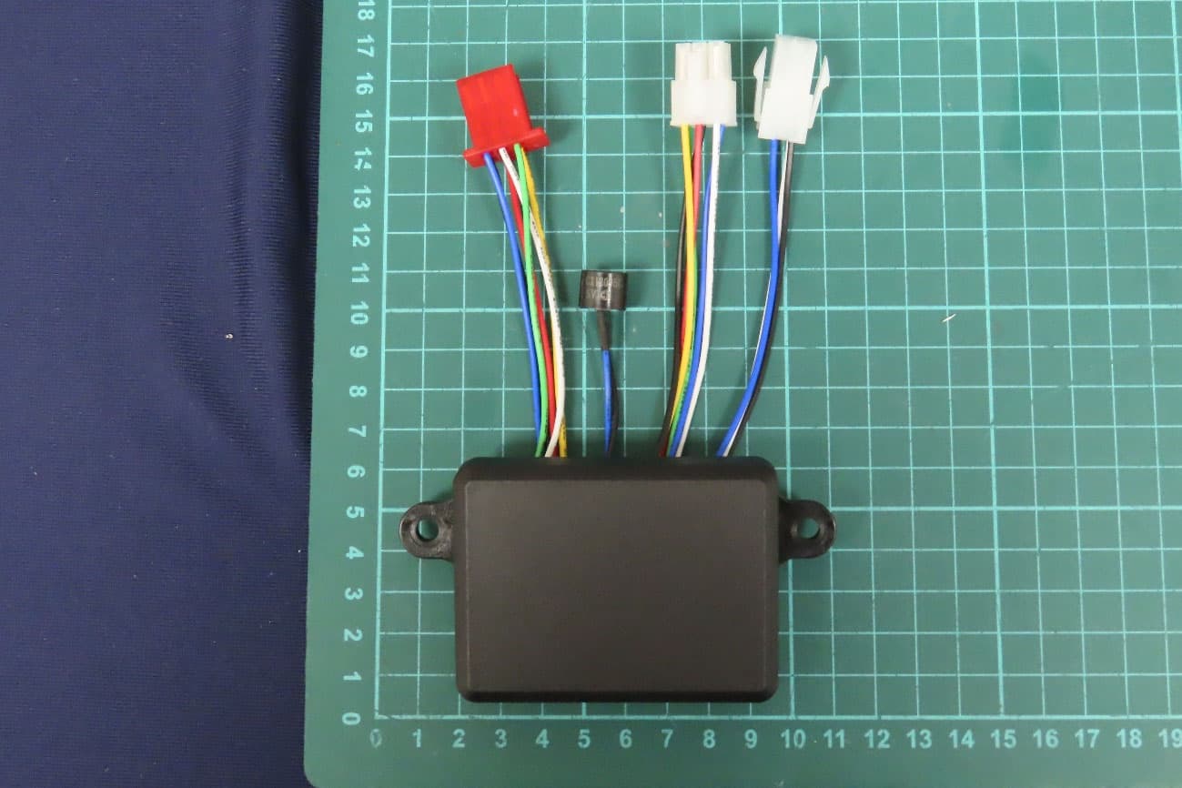
X96884134
Jan 02, 2023Wireless Remote Control
Equipment Class
DTS - Digital Transmission System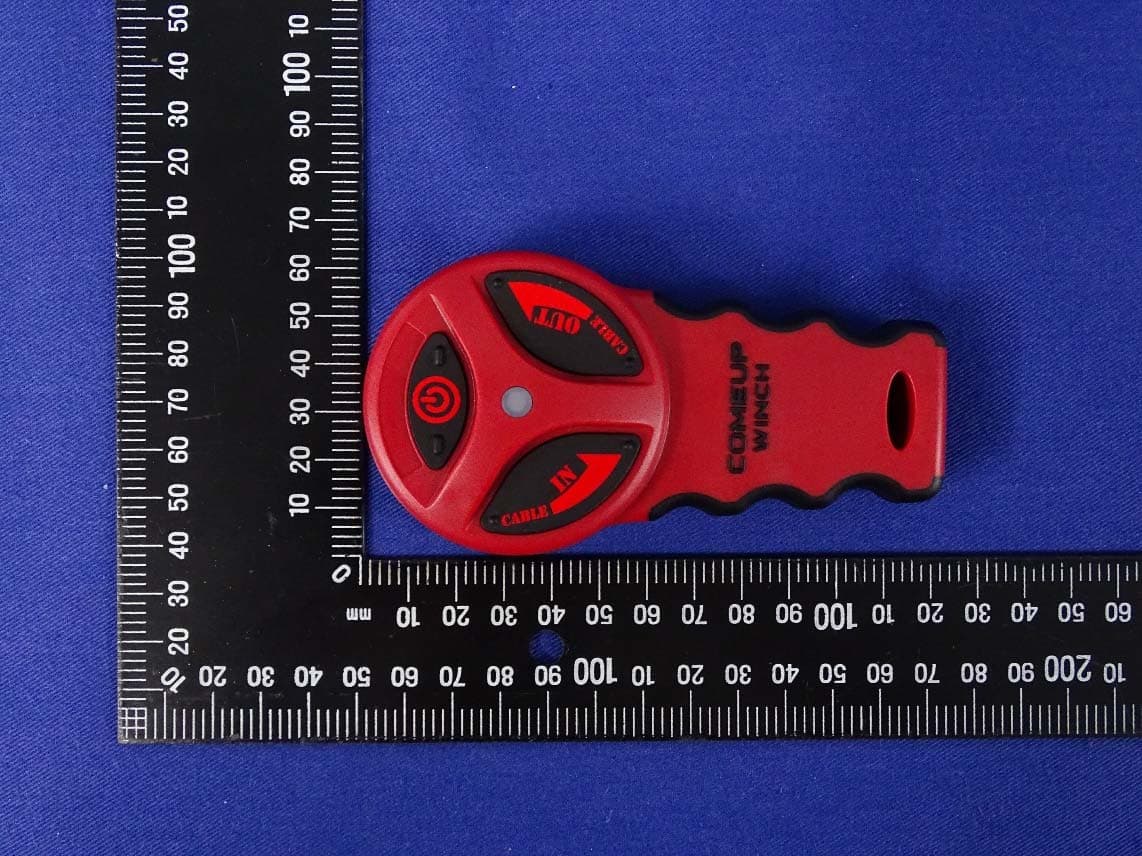
X96883822
Aug 05, 2020Wireless Remote Control
Equipment Class
DTS - Digital Transmission System
X96881490
Oct 06, 2010Wireless Remote Control
Equipment Class
DXX - Part 15 Low Power Communication Device Transmitter