X96883822Wireless Remote Control
Comeup Industries Inc.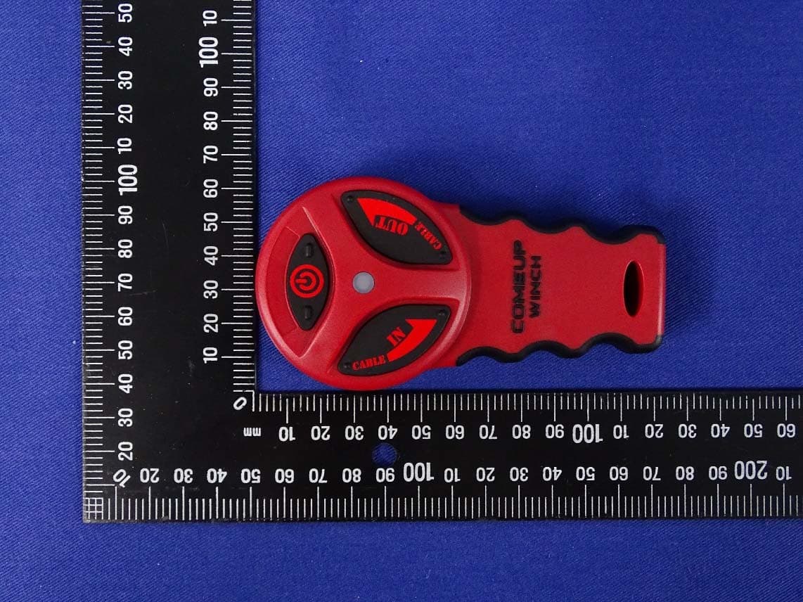
Click to zoom
Application Details
- Equipment Class
- DTS - Digital Transmission System
- Date of Grant
- Aug 05, 2020
- Application Purpose
- Original Equipment
- Date of Application
- Aug 04, 2020
- Equipment Note
- Wireless Remote Control
- Frequency Range
- 2402.00000000 - 2480.00000000
- Company
- Comeup Industries Inc.
- Country
- Taiwan
Documents & Files
Document Text
Text extracted from the exhibit documents filed with the FCC. Open a document above to read the original.
Users Manual
1 RF-24DP-D Wireless Remote Control For Cub series ATV/UTV Winch 1. 2. Wireless Control Kit includes: 1 Wireless Receiver.881103 2 Wiring Harness 1250 mm. 3 Wireless Transmitter.883822 4 Lithium Battery: 3V CR2032 5.Handsaver Strap. 3. 4. 5. I.Specifications 1. Transmission range: 15 ~ 27 m (50 ~ 90 ft) 2. Receiver operation voltage: 8 ~ 24 V 3. Receiver fuse current rating: 7.5A 4. Protection: IP-66 5. Operating temperature range: -20°C ~ +70°C 6. LED indication: Green light for power on; Red light for winching; Blinking green for low battery life; Blinking red light for poor signal received II.Installation Guide Step 1: Connect the wiring a. Connect the Black and Green wires to the same color wires on the contactor and handlebar trigger switch respectively shown on the wiring diagram. b. Slice the Red wire to the receiver fuse then connect to the positive (+) terminal of the battery. c. Connect the Black wire to the negative (-) terminal of the battery. Step 2: Mount the Receiver a. The receiver should be mounted in a clear and dry location. b. Mount on a flat surface with 2 pcs of Ø7 mm mounting holes on each side of the receiver. INSTALLATION GUIDE Minimum of one mounting hole each side Part No.883873 LED indication 2 III Operation 1. Install and replace battery. a. Turn cover counterclockwise to open. b. Replace new battery and put the cover back. c. Turn cover clockwise to close. 2. Start a. Turn on the ATV/UTV. b. Press the Power button for 5 seconds until Green light comes on. c. Press the Cable In or Cable Out button , then the Red light comes on. 3. Stop a. The system will be automatically shutting down the operation after a silence of operation for 5 minutes. b. Press and hold the Power Button for 5 seconds for shutting down the operation. 4. Additional Emergency Stop Function: The power button also works as an emergency stop if the radio control is in malfunction of any reason. While the radio control is in operation (either winch in or winch out, the red light is on), once power button is pressed, the radio control will be forced to power off immediately. Winch will stop running accordingly. 5. Reset a. Press and hold the Programming Button for 5 seconds until the Red lights up. b. Press the Power Buttons for 5 seconds until the Green lights up. c. Press the Cable In or Out button until the Red lights on the receiver turns off. d. Reset is now completed. Please note only one remote can be reset for each receiver. 6. Notes a. The wireless remote control and handlebar rocker switch can be exchanged for activating the winch, but it takes about 10 seconds for exchanging。 b. Blinking Green LED light shows batter low, the battery should be replaced immediately. c. Please note only one remote can be reset for each receiver. d. Blinking Red LED for poor signal. FEDERAL COMMUNICATIONS COMMISSION INTERFERENCE STATEMENT This equipment has been tested and found to comply with the limits for a Class B digital device, pursuant to part 15 of the FCC Rules. These limits are designed to provide reasonable protection against harmful interference in a residential installation. This equipment generates, uses and can radiate radio frequency energy and, if not installed and used in accordance with the instructions, may cause harmful interference to radio communications. However, there is no guarantee that interference will not occur in a particular installation. If this equipment does cause harmful interference to radio or television reception, which can be determined by turning the equipment off and on, the user is encouraged to try to correct the interference by one or more of the following measures: -Reorient or relocate the receiving antenna. -Increase the separation between the equipment and receiver. -Connect the equipment into an outlet on a circuit different from that to which the receiver is connected. -Consult the dealer or an experienced radio/ TV technician for help. CAUTION: Any changes or modifications not expressly approved by the grantee of this device could void the user's authority to operate the equipment. RF exposure warning The equipment complies with FCC RF exposure limits set forth for an uncontrolled environment. The equipment must not be co-located or operating in conjunction with any other antenna or transmitter. FCC and Industry Canada (IC) Warning: • This device complies with Part 15 of the FCC Rules. Operation is subject to the following two conditions: (1) This device may not cause harmful interference, and (2) this device must accept any interference received, including interference that may cause Lithium Battery: CR2032 (3V) Cable OUT Cable IN Cable OUT Cable IN Power Button LED Indicator
Attestation Statements
Federal Communications Commission Authorization and Evaluation Division July 27, 2020 ATTESTATION FCC ID: X96883822 Product: Wireless Remote Control Model: 883822 We don’t provide any controls or software to allow operation outside the USA frequency band when we sell a product bearing the FCC ID: X96883822 anywhere in the world. Sincerely, ------------------------------------------------------------ Vincent Lin, Director, DEKRA Testing and Certification Co., Ltd
Cover Letter(s)
FCC ID.: X96883822 Date: July 27, 2020 Federal Communications Commission Authorization and Evaluation Division Confidentiality Request Pursuant to Sections 0.457 and 0.459 of the Commission’s Rules, the Applicant Hereby requests confidential treatment of information accompanying this Application As outlined below: Type of Confidentiality Requested Exhibit ܈ Permanent Block Diagrams ܆ Short Term External Photos ܆ Short Term Internal Photos ܈ Permanent Operation Description/Theory of Operation ܆ Permanent Parts List & Placement/BOM ܆ Permanent Tune-Up Procedure ܈ Permanent Schematics ܆ Short Term Test Setup Photos ܆ Short Term User’s Manual The above materials contain trade secrets and proprietary information not customarily Released to the public. The public disclosure of these matters might be harmful to the Applicant and provide unjustified benefits to its competitors. The Applicant understands that pursuant to Rule 0.457, disclosure of this Application and all accompanying documentation will not be made before the date of the Grant for this application. Permanent Confidentiality: The applicant requests the exhibits listed above as permanently confidential be permanently withheld from public review due to materials that contain trade secrets and proprietary information not customarily released to the public Short-Term Confidentiality: The applicant requests the exhibits selected above as short term confidential be withheld from public view for a period of 180 days from the date of the Grant of Equipment Authorization and prior to marketing. This is to avoid premature release of sensitive information prior to marketing or release of the product to the public. Sincerely, ------------------------------------------------------ Ben Huang/Director/ COMEUP INDUSTRIES INC.
External Photos
Report No.: 2030763R-E3032110108 Page : 1 of 3 Attachment 2 : EUT Detailed Photographs (1) EUT Photo (2) EUT Photo Report No.: 2030763R-E3032110108 Page : 2 of 3 (3) EUT Photo (4) EUT Photo Report No.: 2030763R-E3032110108 Page : 3 of 3 (5) EUT Photo (6) EUT Photo
ID Label/Location Info
COMEUP INDUSTRIES INC. FCC ID: X96883822 No.139, Jieyukeng Rd., Ruifang Dist., New Taipei City 22453, Taiwan TEL: +886-2-24971788 FCC ID Label
ID Label/Location Info
COMEUP INDUSTRIES INC. FCC ID: X96883822 No.139, Jieyukeng Rd., Ruifang Dist., New Taipei City 22453, Taiwan TEL: +886-2-24971788 The FCC ID will be placed on the equipment as shown in the photograph below.
Internal Photos
Report No.: 2030763R-E3032110108 Page : 1 of 7 Attachment 2 : EUT Detailed Photographs (1) EUT Photo (2) EUT Photo Report No.: 2030763R-E3032110108 Page : 2 of 7 (3) EUT Photo (4) EUT Photo Report No.: 2030763R-E3032110108 Page : 3 of 7 (5) EUT Photo (6) EUT Photo Report No.: 2030763R-E3032110108 Page : 4 of 7 (7) EUT Photo (8) EUT Photo RF Module Antenna Report No.: 2030763R-E3032110108 Page : 5 of 7 (9) EUT Photo (10) EUT Photo Report No.: 2030763R-E3032110108 Page : 6 of 7 (11) EUT Photo (12) EUT Photo Report No.: 2030763R-E3032110108 Page : 7 of 7 (13) EUT Photo
RF Exposure Info
Report No.: 2030763R-SAUSP03V00 Page: 1 of 5 RF Exposure Evaluation Report Product Name : Wireless Remote Control Model No. : 883822 FCC ID : X96883822 Applicant : COMEUP INDUSTRIES INC. Address : No.139, Jieyukeng Rd., Ruifang Dist., New Taipei City 22453, Taiwan Date of Receipt : Mar. 27, 2020 Date of Declaration : Jul. 17, 2020 Report No. : 2030763R-SAUSP03V00 Report Version : V1.0 The test results relate only to the samples tested. The test results shown in the test report are traceable to the national/international standard through the calibration report of the equipment and evaluated measurement uncertainty herein. This report must not be used to claim product endorsement by TAF or any agency of the government. The test report shall not be reproduced without the written approval of DEKRA Testing and Certification Co., Ltd. Measurement uncertainties evaluated for each testing system and associated connections are given here to provide the system information for reference. Compliance determinations do not take into account measurement uncertainties for each testing system, but are based on the results of the compliance measurement. Report No.: 2030763R-SAUSP03V00 Page: 2 of 5 Issued Date: Jul. 17, 2020 Report No.: 2030763R-SAUSP03V00 Product Name Wireless Remote Control Applicant COMEUP INDUSTRIES INC. Address No.139, Jieyukeng Rd., Ruifang Dist., New Taipei City 22453, Taiwan Manufacturer COMEUP INDUSTRIES INC. Model No. 883822 FCC ID. X96883822 Trade Name COMEUP Applicable Standard KDB 447498 D01 v06 Minimum test separation distance ≥ 20 cm For low power devices Test Result Complied Documented By : ( Senior Adm. Specialist / Joanne Lin ) Tested By : ( Senior Engineer / Wen Lee ) Approved By : ( Director / Vincent Lin ) Report No.: 2030763R-SAUSP03V00 Page: 3 of 5 Revision History Report No. Version Description Issued Date 2030763R-SAUSP03V00 V1.0 Initial issue of report. 2020-07-17 Report No.: 2030763R-SAUSP03V00 Page: 4 of 5 1. GENERAL INFORMATION 1.1. EUT Description Product Name Wireless Remote Control Trade Name COMEUP Model No. 883822 FCC ID. X96883822 Frequency Range 2402-2480MHz Channel Number 79CH Type of Modulation GFSK Antenna Type PCB Antenna Channel Control Auto Antenna Gain Refer to the table “Antenna List” Antenna List No. Manufacturer Part No. Antenna Type Peak Gain 1 COMEUP N/A PCB Antenna -0.24dBi for 2.4GHz Report No.: 2030763R-SAUSP03V00 Page: 5 of 5 2. RF Exposure Evaluation 2.1. Standard Applicable According to 1.1307 (b)(1), systems operating under the provisions of this section shall be operated in a manner that ensure that the public is not exposed to radio frequency energy level in excess of the Commission’s guideline. 2.2. Measurement Result: According to KDB Publication 447498 D01, section 4.3.1, per the calculations of item 1 (Power(mW)/separation (mm)*sqrt(f(GHz)≤3.0), SAR is required as shown in the table below where calculated values are greater than 3.0: 1.) Operation frequency = 2450MHz and antenna separation distance = 5mm, SAR Test Exclusion Threshold = 10mW Frequency Band Conducted maximum Peak Power SAR Test Exclusion Threshold Calculated Threshold Value (≦3.0 SAR is not required) (dBm) (mW) (mW) 2441MHz -4.25 0.38 10 0.116 Note1: The SAR/MPE measurement is not necessary. Note2: The conducted output power is refer to report No.: 2030763R-RFUSP01V00-A from the DEKRA.
Test Report
Report No.: 2030763R-RFUSP01V00-A Page: 1 of 55 FCC Test Report Product Name Wireless Remote Control Model No. 883822 FCC ID. X96883822 Applicant COMEUP INDUSTRIES INC. Address No.139, Jieyukeng Rd., Ruifang Dist., New Taipei City 22453, Taiwan Date of Receipt Mar. 27, 2020 Issued Date Jul. 17, 2020 Report No. 2030763R-RFUSP01V00-A Report Version V1.0 The test results relate only to the samples tested. The test results shown in the test report are traceable to the national/international standard through the calibration report of the equipment and evaluated measurement uncertainty herein. This report must not be used to claim product endorsement by TAF or any agency of the government. The test report shall not be reproduced without the written approval of DEKRA Testing and Certification Co., Ltd. Measurement uncertainties evaluated for each testing system and associated connections are given here to provide the system information for reference. Compliance determinations do not take into account measurement uncertainties for each testing system, but are based on the results of the compliance measurement. Report No.: 2030763R-RFUSP01V00-A Page: 2 of 55 Test Report Issued Date: Jul. 17, 2020 Report No.: 2030763R-RFUSP01V00-A Product Name Wireless Remote Control Applicant COMEUP INDUSTRIES INC. Address No.139, Jieyukeng Rd., Ruifang Dist., New Taipei City 22453, Taiwan Manufacturer COMEUP INDUSTRIES INC. Model No. 883822 FCC ID. X96883822 EUT Rated Voltage DC 3V (Power by battery) EUT Test Voltage DC 3V (Power by battery) Trade Name COMEUP Applicable Standard FCC CFR Title 47 Part 15 Subpart C ANSI C63.4: 2014, ANSI C63.10: 2013 Test Result Complied Documented By : ( Senior Adm. Specialist / Joanne Lin ) Tested By : ( Senior Engineer / Ivan Chuang ) Approved By : ( Director / Vincent Lin ) Report No.: 2030763R-RFUSP01V00-A Page: 3 of 55 TABLE OF CONTENTS Description Page 1. GENERAL INFORMATION ............................................................................................................... 5 1.1. EUT Description ...................................................................................................................................... 5 1.2. Operational Description ........................................................................................................................... 7 1.3. Tested System Details .............................................................................................................................. 8 1.4. Configuration of Tested System .............................................................................................................. 8 1.5. EUT Exercise Software ........................................................................................................................... 8 1.6. Test Facility ............................................................................................................................................. 9 1.7. List of Test Equipment ........................................................................................................................... 10 1.8. Uncertainty ............................................................................................................................................ 11 2. CONDUCTED EMISSION ................................................................................................................ 12 2.1. Test Setup .............................................................................................................................................. 12 2.2. Limits ..................................................................................................................................................... 12 2.3. Test Procedure ....................................................................................................................................... 13 2.4. Test Result of Conducted Emission ....................................................................................................... 13 3. PEAK POWER OUTPUT .................................................................................................................. 14 3.1. Test Setup .............................................................................................................................................. 14 3.2. Limit ...................................................................................................................................................... 14 3.3. Test Procedure ....................................................................................................................................... 14 3.4. Test Result of Peak Power Output ......................................................................................................... 15 4. RADIATED EMISSION ..................................................................................................................... 16 4.1. Test Setup .............................................................................................................................................. 16 4.2. Limits ..................................................................................................................................................... 17 4.3. Test Procedure ....................................................................................................................................... 18 4.4. Test Result of Radiated Emission .......................................................................................................... 20 5. RF ANTENNA CONDUCTED TEST ................................................................................................ 34 5.1. Test Setup .............................................................................................................................................. 34 5.2. Limits .............................................................................................…
Text truncated - open the document above for the full version.
Test Setup Photos
Report No.: 2030763R-E3032110108 Page : 1 of 2 Attachment 1: EUT Test Setup Photographs Front View of Radiated Test Back View of Radiated Test Report No.: 2030763R-E3032110108 Page : 2 of 2 Front View of Radiated Test (Horn) Back View of Radiated Test (Horn)
Contact Information
Applicant
Ben Huang(Director)
Test Firm
DEKRA TESTING AND CERTIFICATION Lin Kou Lab.Mirenda Liao
[email protected]886-2-2602-7968
Technical Specifications
| # | Rule Parts | Frequency Range | Power Output |
|---|---|---|---|
| 1 | 15C | 2.40 GHz - 2.48 GHz | 400.00 µW |
Other Applications from Comeup Industries Inc.

X96884242
Jan 02, 2023Wireless Remote Control
Equipment Class
DTS - Digital Transmission System
X96884212
Jan 02, 2023Wireless Remote Control
Equipment Class
DTS - Digital Transmission System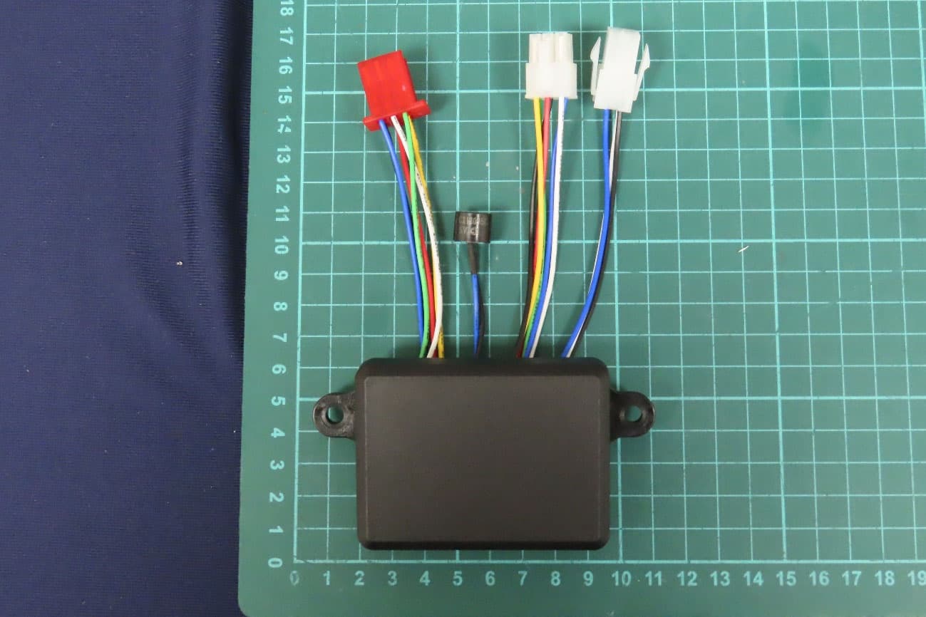
X96884134
Jan 02, 2023Wireless Remote Control
Equipment Class
DTS - Digital Transmission System
X96882756
May 10, 2015Wireless Remote Control
Equipment Class
DXX - Part 15 Low Power Communication Device Transmitter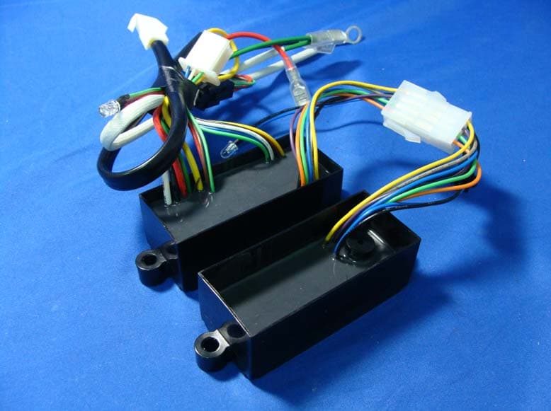
X96881490
Oct 06, 2010Wireless Remote Control
Equipment Class
DXX - Part 15 Low Power Communication Device Transmitter