X9S-AS1000THE AREASENSOR COMMUNICATED W/THE BEACON & PROX DEVS
Proxense LLC
Click to zoom
Application Details
- Equipment Class
- DTS - Digital Transmission System
- Date of Grant
- Jan 20, 2011
- Application Purpose
- Original Equipment
- Date of Application
- Jan 19, 2011
- Equipment Note
- THE AREASENSOR COMMUNICATED W/THE BEACON & PROX DEVS
- Frequency Range
- 2475.10000000 - 2480.00000000
- Company
- Proxense LLC
- Country
- United States
Documents & Files
Document Text
Text extracted from the exhibit documents filed with the FCC. Open a document above to read the original.
Users Manual
Note: Instal llation must b Are be performed eaSen by a Proxens nsor In se authorized nstall professional lation installer. n Guidde MODEL NUMBER: AS1000 Page i MODEL NUMBER: AS1000 INSTALLATION: This product MUST be installed by a Proxense authorized professional installer. FCC STATEMENTS: THIS DEVICE COMPLIES WITH PART 15 OF THE FCC RULES. OPERATION IS SUBJECT TO THE FOLLOWING TWO CONDITIONS: (1) THIS DEVICE MAY NOT CAUSE HARMFUL INTERFERENCE, AND (2) THIS DEVICE MUST ACCEPT ANY INTERFERENCE RECEIVED, INCLUDING INTERFERENCE THAT MAY CAUSE UNDESIRED OPERATION. THE MANUFACTURER IS NOT RESPONSIBLE FOR ANY RADIO OR TV INTERFERENCE CAUSED BY UNAUTHORIZED MODIFICATIONS TO THIS EQUIPMENT. SUCH MODIFICATIONS COULD VOID THE USER’S AUTHORITY TO OPERATE THE EQUIPMENT. © 2010 Proxense, LLC. All rights reserved. Proxense, the Proxense logo, and other Proxense marks are owned by Proxense, LLC and may be registered. All other trademarks are the property of their respective owners. Proxense assumes no responsibility for any errors that may appear in this guide. Information contained herein is subject to change without notice. Corporate Office: Proxense, LLC 689 NW Stonepine Drive Bend, OR 97701 541.382.5745 DOCUMENT NUMBER: PX-9000-0003-00 Revision Log: This log identifies those portions of this document, which have been revised since the initial release and the date of each revision. Date Version Revisions 08/16/10 00 Initial Release AreaSensor Installation Guide MODEL NUMBER: AS1000 Page 2 Introduction This Installation Guide is written for a Proxense authorized installation professional. Only a Proxense authorized installation professional may install this product. There are three steps to the installation: • Before you start • Installing the AreaSensor • Provisioning the AreaSensor Step 1: Before you start To ensure that you have the most recent version of this guide, be sure to check our FTP site before you start the installation. Package Contents Your package includes the following items: • This Guide • One AreaSensor • One Mounting Kit Your package maybe part of a master pack where multiple AreaSensors and one copy of this guide will be provided. Minimum Requirements • ProxNet installation site survey which lists the following: a. The available 802.3AF network port number / cable location b. The installation location of the AreaSensor AreaSensor Installation Guide MODEL NUMBER: AS1000 Page 3 Step 2: Installing the AreaSensor Installing the mounting bracket 1. Find the AreaSensor mounting location, bracket type, mounting angle from the ProxNet installation survey. 2. Using this information install the mounting bracket. Connecting the AreaSensor to the 802.3AF network Connect the 802.3AF network cable to the AreaSensor’s RJ45 connector. Mounting the AreaSensor Following the mounting bracket instructions attach the AreaSensor to the mounting bracket. Step 3: Provisioning the AreaSensor You have completed the physical installation. Please contact the system administrator who must now provision the AreaSensor. If you need technical assistance Telephone: 561.798.6166 Email: [email protected]
Cover Letter(s)
August 16th, 2010 Federal Communications Commission Authorization and Evaluation Division Confidentiality Request regarding application for certification – Product Name: AreaSensor Model No: AS1000 P/N: PX-7100-0003-00 FCC ID: X9S-AS1000 Pursuant to Sections 0.457 and 0.459 of the Commission’s Rules, we hereby request long term confidential treatment of information accompanying this application as listed below: 1. Schematic Diagram AS1000 (P2) – Schematic_FCC_1.0.pdf 2. Parts List AS1000 (P2) – Parts List_FCC_1.0.pdf 3. Block Diagram AS1000 (P2) – Block Diagram_FCC_1.0.pdf 4. Theory of Operation AS1000 (P2) – Theory of Operation_FCC_1.0.pdf The above documents contain trade secrets and proprietary information not customarily released to the public. The public disclosure of these documents may be harmful to the applicant and provide unjustified benefits to its competitors. The applicant understands that pursuant to Section 0.457 of the rules, disclosure of this application and all accompanying documentation will not be made before the date of the Grant for this application. Further, the applicant understands that the documents listed above as requiring long term confidential treatment will remain undisclosed indefinitely. Sincerely, Wayne Becker Sr. Engineer Proxense, LLC Florida Office (Engineering): 1013 N State Road 7 Royal Palm Beach, FL 33411 561.798.6166 Ext 124
External Photos
Product Name: AreaSensorModel No: AS1000P/N: PX-7100-0003-00HW Build: P2FCC ID: X9S-AS1000 External Photos Proxense, LLC Front Rear Page 1 of 4Rev 1.0 Rear External Photos Proxense, LLC Page 2 of 4Rev 1.0 Sides (12) – No RF/electrical connections ANT A – SMA Jack ANT C – MMCX Jack Network & Power (POE)– RJ45 Jack ANT D – MMCX Jack ANT B – SMA Jack Product Name: AreaSensorModel No: AS1000P/N: PX-7100-0003-00HW Build: P2FCC ID: X9S-AS1000 External Photos Proxense, LLC Page 3 of 4Rev 1.0 AreaSensor mounted into above ceilin g (Plenum space) mounting bracket Above ceiling (Plenum sp ace) mounting bracket Product Name: AreaSensorModel No: AS1000P/N: PX-7100-0003-00HW Build: P2FCC ID: X9S-AS1000 External Photos Proxense, LLC Page 4 of 4Rev 1.0 AreaSensor attached to be low ceiling mounting bracket Below ceiling mounting bracket Product Name: AreaSensorModel No: AS1000P/N: PX-7100-0003-00HW Build: P2FCC ID: X9S-AS1000
ID Label/Location Info
Product Name: AreaSensorModel No: AS1000P/N: PX-7100-0003-00HW Build: P2FCC ID: X9S-AS1000 FCC ID Label Artwor k & Label Location Proxense, LLC Scale: 1:1 Page 1 of 1Rev 1.0 S/N: 1 234 56 789 0 1234 5 678 9 L/C: Z ZZ ZZZ -Z Z M ad e i n th e US A 1234567890123456 7890 MAC ID: 1234567890123456789 12345678901234567890 ABC DEFGH 48V xxxmA PROXENSE Model No: AS1000 P/N: PX-7100-0003-00 FCC ID: X9S-AS1000 IC: 9282A-AS1000 Exxxxxx THIS DEVICE COMPLIES WITH PART 15 OF THE FCC RULES. OPERATION IS SUBJECT TO THE FOLLOWING TWO CONDITIONS: (1) THIS DEVICE MAY NOT CAUSE HARMFUL INTERFERENCE, AND (2) THIS DEVICE MUST ACCEPT ANY INTERFERENCE RECEIVED, INCLUDING INTERFERENCE THAT MAY CAUSE UNDESIRED OPERATION. Dimensions: 2.5 x 0.375" RC 0.125"
Internal Photos
Product Name: AreaSensorModel No: AS1000P/N: PX-7100-0003-00HW Build: P2FCC ID: X9S-AS1000 Internal Photos Proxense, LLC Page 1 of 4Rev 1.0 Internal Photos Proxense, LLC Page 2 of 4Rev 1.0 Product Name: AreaSensorModel No: AS1000P/N: PX-7100-0003-00HW Build: P2FCC ID: X9S-AS1000 Internal Photos Proxense, LLC Page 3 of 4Rev 1.0 Product Name: AreaSensorModel No: AS1000P/N: PX-7100-0003-00HW Build: P2FCC ID: X9S-AS1000 Internal Photos Proxense, LLC Page 4 of 4Rev 1.0 Product Name: AreaSensorModel No: AS1000P/N: PX-7100-0003-00HW Build: P2FCC ID: X9S-AS1000
Operational Description
Patch Module V Polar H Polar ANT CANT D ANT AANT B T TruProx A AccessP Point Integrated Omni (x2) TX/RX ANT1 ANT2 TX/RX ANT A (RX only) : Various directional antennas:Teletronics: P/N:15-537 (15dBi; 20 degree beam width) ANT B (RX only) : Various directional antennas:Teletronics: P/N:15-537 (15dBi; 20 degree beam width) Antenna Technical Description Page 1 of 6Rev 1.1 Proxense, LLC SMAMMCX Product Name: AreaSensorModel No: AS1000P/N: PX-7100-0003-00HW Build: P2FCC ID: X9S-AS1000
RF Exposure Info
Timco Engineering Prediction of MPE limit at a given distance Equation from page 18 of OET Bulletin 65, Edition 97-01 where:S = power density P = power input to the antenna G = power gain of the antenna in the direction of interest relative to an isotropic radiator R = distance to the center of radiation of the antenna Maximum peak output power at antenna input terminal:17.80(dBm) Maximum peak output power at antenna input terminal:60.25595861(mW) Antenna gain(typical):4.5(dBi) Maximum antenna gain:2.818382931(numeric) Time Averaging:100(%) Prediction distance:20(cm) Prediction frequency:2450(MHz) MPE limit for uncontrolled exposure at prediction frequency:1(mW/cm^2) Power density at prediction frequency:0.033785(mW/cm^2) Margin of compliance:-14.7(dB) This equates to0.33785484W/m^2 2 4R PG S π =
Test Report
FCC PART 15.247 AND IC RSS-210 TEST REPORT DIGITAL SPREAD SPECTRUM Applicant PROXENSE, LLC. Address 1013 N. State Road 7 Royal Palm Beach, Fl. 33411 USA FCC ID X9S-AS1000 IC 9282A-AS1000 Model Number AS1000 Product Description Area Sensor with 4.5dBi patch antenna Date Sample Received 7/21/2010 Date Tested 7/22/2010 Tested By Richard Block Approved By Mario R. de Aranzeta Report Number 1680AT10TestReport_Ant 1.doc Test Results PASS FAIL THE ATTACHED REPORT SHALL NOT BE REPRODUCED EXCEPT IN FULL WITHOUT THE WRITTEN APPROVAL OF TIMCO ENGINEERING, INC. 849 NW State Road 45 Newberry, FL 32669 USA Ph: 888.472.2424 or 352.472.5500 Fax: 352.472.2030 Email: [email protected] Website: www.timcoengr.com Testing Certificate # 0955-01 APPLICANT: PROXENSE, LLC. FCC ID: X9S-AS1000 IC: 9282A-AS1000 REPORT: Y:\P\PROXENSE\1680AT10\1680AT10TestReport_Ant 1.doc Page 2 of 29 Mdea 3.14.2008 TABLE OF CONTENT GENERAL REMARKS ............................................................................................................................... 3 GENERAL INFORMATION ........................................................................................................................ 4 EMC EQUIPMENT LIST............................................................................................................................ 5 TEST PROCEDURES ................................................................................................................................ 6 CALCULATION OF DUTY CYCLE ............................................................................................................. 7 RADIATION INTERFERENCE ................................................................................................................. 10 POWER LINE CONDUCTED INTERFERENCE ........................................................................................ 15 OCCUPIED BANDWIDTH ....................................................................................................................... 16 SPURIOUS EMISSIONS AT ANTENNA TERMINALS ............................................................................... 19 RADIATED SPURIOUS EMISSIONS INTO ADJACENT RESTRICTED BAND .......................................... 21 POWER SPECTRAL DENSITY ................................................................................................................ 28 RADIATED EMISSIONS TEST SETUP PHOTO ....................................................................................... 29 APPLICANT: PROXENSE, LLC. FCC ID: X9S-AS1000 IC: 9282A-AS1000 REPORT: Y:\P\PROXENSE\1680AT10\1680AT10TestReport_Ant 1.doc Page 3 of 29 Mdea 3.14.2008 GENERAL REMARKS The attached report shall not be reproduced except in full without the written permission of Timco Engineering Inc. The test results relate only to the items tested. Summary The device under test does: fulfill the general approval requirements as identified in this test report not fulfill the general approval requirements as identified in this test report Attestations This equipment has been tested in accordance with the standards identified in this test report. To the best of my knowledge and belief, these tests were performed using the measurement procedures described in this report. All instrumentation and accessories used to test products for compliance to the indicated standards are calibrated regularly in accordance with ISO 17025 requirements. Testing Certificate # 0955-01 I attest that the necessary measurements were made, under my supervision, at: Timco Engineering Inc. 849 NW State Road 45 Newberry, Fl 32669 Authorized Signatory Name: Mario de Aranzeta C.E.T. Compliance Engineer/ Lab. Supervisor Date: November 15 th , 2010 APPLICANT: PROXENSE, LLC. FCC ID: X9S-AS1000 IC: 9282A-AS1000 REPORT: Y:\P\PROXENSE\1680AT10\1680AT10TestReport_Ant 1.doc Page 4 of 29 Mdea 3.14.2008 GENERAL INFORMATION DUT Specification Applicable Standard Part 15.247, RSS-210, RSS-GEN DUT Description Area Sensor with 4.5dBi patch antenna FCC ID X9S-AS1000 IC 9282A-AS1000 Operating Frequency TX: 2405-2480 MHz DUT Power Source 110–120Vac/50– 60Hz DC Power PoE (Power over Ethernet) Battery Operated Exclusively Test Item Prototype Pre-Production Production Type of Equipment Fixed Mobile Portable Antenna Connector SMA Antenna 4.5dBi patch Test Facility Timco Engineering Inc. located at 849 NW State Road 45 Newberry, FL 32669 USA. Test Conditions Temperature: 26ºC Relative humidity: 50% Test Exercise The DUT was placed in continuous transmit mode of operation. Test Supporting Equipment Supporting Device Manufacturer Model / FCC ID Serial Number N/A APPLICANT: PROXENSE, LLC. FCC ID: X9S-AS1000 IC: 9282A-AS1000 REPORT: Y:\P\PROXENSE\1680AT10\1680AT10TestReport_Ant 1.doc Page 5 of 29 Mdea 3.14.2008 EMC EQUIPMENT LIST Device Manufacturer Model Serial Number Cal/Char Date Due Date 3-Meter Semi- Anechoic Chamber Panashield N/A N/A Listed 3/10/10 3/10/12 AC Voltmeter HP 400FL 2213A14499 CAL 3/23/09 3/23/11 Antenna: Dipole Kit Electro- Metrics TDA-30/1-4 153 CHAR 6/10/09 6/10/11 Frequency Counter HP 5385A 3242A07460 CAL 5/26/09 5/26/11 Hygro- Thermometer Extech 445703 0602 CAL 1/30/09 1/30/11 Modulation Analyzer HP 8901A 3435A06868 CAL 5/26/09 5/26/11 Digital Multimeter Fluke FLUKE-77-3 79510405 CAL 5/18/09 5/18/11 Analyzer Tan Tower Preamplifier HP 8449B-H02 3008A00372 CAL 11/21/09 11/21/11 Analyzer Tan Tower Quasi- Peak Adapter HP 85650A 3303A01690 CAL 11/22/09 11/22/11 Analyzer Tan Tower RF Preselector HP 85685A 3221A01400 CAL 11/21/09 11/21/11 Analyzer Tan Tower Spectrum Analyzer HP 8566B Opt 462 3138A07786 3144A20661 CAL 11/24/09 11/24/11 Temperature Chamber Tenney Engineering TTRC 11717-7 CHAR 4/25/10 4/25/12 APPLICANT: PROXENSE, LLC. FCC ID: X9S-AS1000 IC: 9282A-AS1000 REPORT: Y:\P\PROXENSE\1680AT10\1680AT10TestReport_Ant 1.doc Page 6 of 29 Mdea 3.14.2008 TEST PROCEDURES Radiation Interference: ANSI C63.4-2003 using a spectrum analyzer, a preselector, a quasi-peak adapter, and a…
Text truncated - open the document above for the full version.
Contact Information
Applicant
Wayne Becker(Senior Engineer)
Test Firm
Timco Engineering, Inc.Bruno Clavier
Technical Specifications
| # | Rule Parts | Frequency Range | Power Output |
|---|---|---|---|
| 2 | 15C | 2.48 GHz - 2.48 GHz | 1.00 mW |
Other Applications from Proxense LLC
X9S-PT1000
Jan 20, 2011THE PROXTAG COMMUNICATES W/THE BEACON & SENSORS
Equipment Class
DTS - Digital Transmission System
X9S-BE1000
Jan 20, 2011THE BEACON IS THE PROXNET SYSTEM COORDINATOR
Equipment Class
DTS - Digital Transmission System
X9S-PB1000
Jan 20, 2011THE PROXBADGE COMMUNICATES W/THE BEACON & SENSORS
Equipment Class
DTS - Digital Transmission System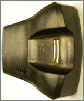
X9S-BS1000
Jan 20, 2011THE BIOSENSOR COMMUNICATES W/THE BEACON & PROX DEV
Equipment Class
DTS - Digital Transmission System